Cam SUZUKI SWIFT 2007 2.G Service Repair Manual
[x] Cancel search | Manufacturer: SUZUKI, Model Year: 2007, Model line: SWIFT, Model: SUZUKI SWIFT 2007 2.GPages: 1496, PDF Size: 34.44 MB
Page 353 of 1496
Downloaded from www.Manualslib.com manuals search engine Engine Lubrication System: 1E-1
Engine
Engine Lubrication System
General Description
Engine Lubrication DescriptionS7RS0B1501001
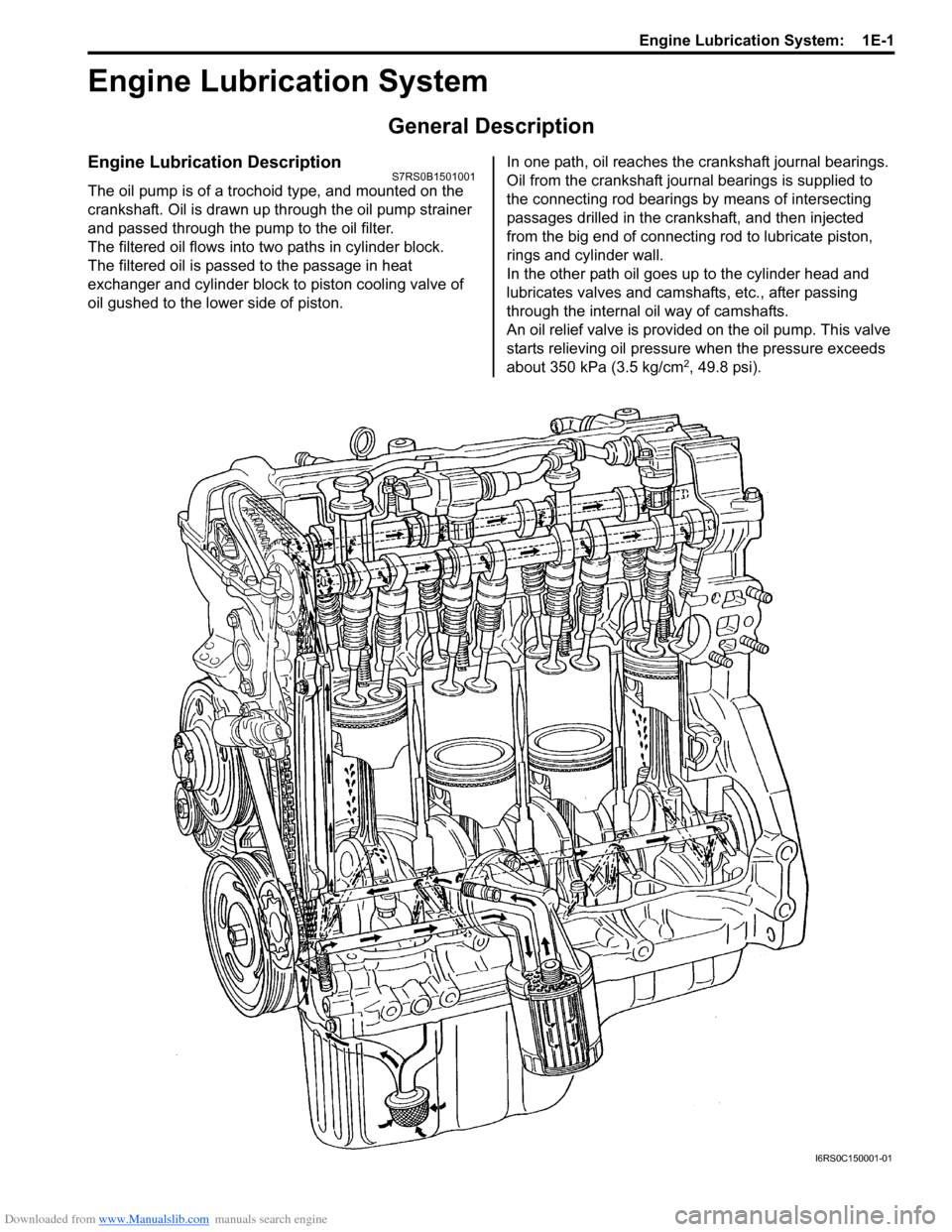
The oil pump is of a trochoid type, and mounted on the
crankshaft. Oil is drawn up through the oil pump strainer
and passed through the pump to the oil filter.
The filtered oil flows into two paths in cylinder block.
The filtered oil is passed to the passage in heat
exchanger and cylinder block to piston cooling valve of
oil gushed to the lower side of piston. In one path, oil reaches the crankshaft journal bearings.
Oil from the crankshaft journal bearings is supplied to
the connecting rod bearings by means of intersecting
passages drilled in the cran
kshaft, and then injected
from the big end of connecting rod to lubricate piston,
rings and cylinder wall.
In the other path oil goes up to the cylinder head and
lubricates valves and camshafts, etc., after passing
through the internal oil way of camshafts.
An oil relief valve is provided on the oil pump. This valve
starts relieving oil pressure when the pressure exceeds
about 350 kPa (3.5 kg/cm
2, 49.8 psi).
I6RS0C150001-01
Page 393 of 1496
Downloaded from www.Manualslib.com manuals search engine Ignition System: 1H-1
Engine
Ignition System
General Description
Ignition System ConstructionS7RS0B1801001
The ignition system is an electronic (distributorless) ignition system. It consists of the parts as described below.
• ECM
It detects the engine and vehicle conditions through the si gnals from the sensors, determines the most suitable
ignition timing and time for electricity to flow to the primar y coil and sends a signal to the ignitor (power unit) in the
ignition coil assembly.
• Ignition coil assembly (including an ignitor)
The ignition coil assembly has a built -in ignitor which turns ON and OFF the current flow to the primary coil
according to the signal from ECM. When the current flow to the primary coil is turned OFF, a high voltage is induced
in the secondary coil.
• High-tension cords and spark plugs
• CMP sensor (Camshaft position sensor) and CKP sensor (Crankshaft position sensor)
Using signals from these sensors, ECM identifies the specific cylinder whose piston is in the compression stroke,
detects the crank angle and adjusts in itial ignition timing automatically.
• TP sensor, ECT sensor, MAP sensor, MAF sensor, IAT sensor, knock sensor and other sensors / switches
Although this ignition system does not have a distributor, it has two ignition coil assemblies (one is for No.1 and No.4
spark plugs and the other is for No.2 and No.3 spark plugs). W hen an ignition signal is sent from ECM to the ignitor in
the ignition coil assembly for No.1 and No.4 spark plugs, a high voltage is induced in the secondary coil and that
passes through the high-tension cords and causes No.1 and No.4 spark plugs to spark simultaneously. Likewise,
when an ignition signal is sent to the ignitor in the ot her ignition coil assembly, No.2 and No.3 spark plugs spark
simultaneously.
Page 396 of 1496
Downloaded from www.Manualslib.com manuals search engine 1H-4 Ignition System:
Diagnostic Information and Procedures
Ignition System Symptom DiagnosisS7RS0B1804001
Reference Waveform of Ignition SystemS7RS0B1804002
Refer to “Reference waveform No.5”, “Reference waveform No.6” and “Reference waveform No.7” under “Inspection
of ECM and Its Circuits in Section 1A” for waveform of Ignition trigger signal.
Ignition System CheckS7RS0B1804003
Condition Possible cause Correction / Reference Item
Engine cranks, but will
not start or hard to start
(No spark) Blown fuse for ignition coil
Replace.
Loose connection or disconnection of
lead wire or high-tension cord(s) Connect securely.
Faulty high-tension cord(s) Replace.
Faulty spark plug(s) Replace.
Faulty ignition coil Replace ignition coil assembly.
Faulty CKP sensor or CKP sensor plate Clean, tighten or replace.
Faulty CMP sensor or sensor rotor tooth
of camshaft Clean, tighten or replace.
Faulty ECM Replace.
Poor fuel economy or
engine performance Incorrect ignition timing
Check related sensors and CKP sensor plate.
Faulty spark plug(s) or high-tension
cord(s) Adjust, clean or replace.
Faulty ignition coil assembly Replace.
Faulty CKP sensor or CKP sensor plate Clean, tighten or replace.
Faulty CMP sensor or sensor rotor tooth
of camshaft Clean, tighten or replace.
Faulty knock sensor Replace.
Faulty ECM Replace.
StepAction YesNo
1 Was “Engine and Emission Control System Check”
performed? Go to Step 2.
Go to “Engine and
Emission Control
System Check in
Section 1A”.
2 Ignition spark test
1) Check all spark plugs for condition and type referring to
“Spark Plug Inspection”.
2) If OK, perform ignition spark test referring to “Ignition Spar k Tes t”.
Is spark emitted from all spark plugs? Go to Step 13. Go to Step 3.
3 DTC check
1) Perform DTC check referring to “DTC Check in Section
1A”.
Is DTC stored in ECM? Go to applicable DTC
diag. flow.
Go to Step 4.
4 Electrical connection check
1) Check ignition coil assemblies and high-tension cords
for electrical connection.
Are they connected securely? Go to Step 5.
Connect securely.
5 High-tension cords check
1) Check high-tension cord for resistance referring to
“High-Tension Cord Inspection”.
Is check result satisfactory? Go to Step 6.
Replace high-tension
cord(s).
Page 397 of 1496
Downloaded from www.Manualslib.com manuals search engine Ignition System: 1H-5
6Ignition coil assembly power supply and ground circuit
check
1) Check ignition coil assembly power supply and ground
circuits for open and short.
Are circuits in good condition? Go to Step 7.
Repair or replace.
7 Ignition coil assembly check
1) Check ignition coil for resistance referring to “Ignition
Coil Assembly (Including ignitor) Inspection”.
Is check result satisfactory? Go to Step 8.
Replace ignition coil
assembly.
8 CKP sensor check
1) Check CKP sensor referring to “CKP Sensor Inspection
in Section 1C”.
Is check result satisfactory? Go to Step 9.
Tighten CKP sensor
bolt, replace CKP
sensor or CKP sensor
plate.
9 CMP sensor check
1) Check CMP sensor referring to “Camshaft Position
(CMP) Sensor Inspection in Section 1C”.
Is check result satisfactory? Go to Step 10. Tighten CMP sensor
bolt, replace CMP
sensor or intake
camshaft.
10 Ignition trigger signal circuit check
1) Check ignition trigger signal wire for open, short and
poor connection.
Is circuit in good condition? Go to Step 11. Repair or replace.
11 A known-good ignition coil assembly substitution
1) Substitute a known-good ignition coil assembly and then
repeat Step 2.
Is check result of Step 2 satisfactory? Go to Step 12. Substitute a known-
good ECM and then
repeat Step 2.
12 Knock sensor check
1) Confirm that knock sensor circuit is in good condition
referring to “DTC P0327 / P0328: Knock Sensor 1 Circuit
Low / High in Section 1A”.
2) Check oscilloscope waveform of knock sensor signal
referring to “Reference waveform No.25” and
“Reference waveform No.26” under “Inspection of ECM
and Its Circuits in Section 1A”.
Is check result satisfactory? Go to Step 13. Substitute a known-
good knock sensor and
recheck.
13 Ignition timing check
1) Check initial ignition timing and ignition timing advance
referring to “Ignition Timing Inspection”.
Is check result satisfactory? System is in good
condition.
Check CMP sensor,
CMP sensor rotor tooth
of camshaft, CKP
sensor, CKP sensor
plate and/or input
signals related to this
system.
Step
Action YesNo
Page 401 of 1496
Downloaded from www.Manualslib.com manuals search engine Ignition System: 1H-9
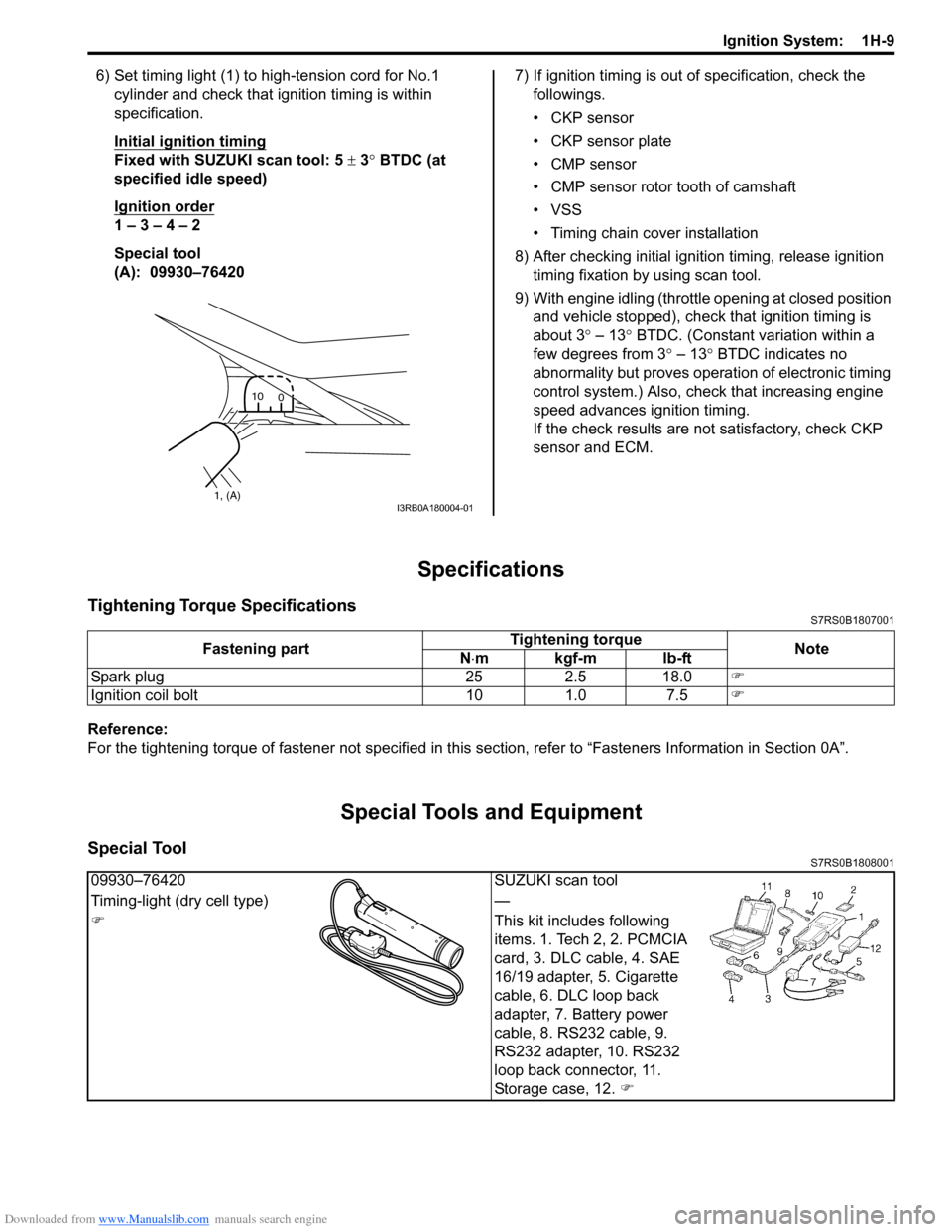
6) Set timing light (1) to high-tension cord for No.1 cylinder and check that ignition timing is within
specification.
Initial ignition timing
Fixed with SUZUKI scan tool: 5 ± 3° BTDC (at
specified idle speed)
Ignition order
1 – 3 – 4 – 2
Special tool
(A): 09930–76420 7) If ignition timing is out
of specification, check the
followings.
• CKP sensor
• CKP sensor plate
• CMP sensor
• CMP sensor rotor tooth of camshaft
• VSS
• Timing chain cover installation
8) After checking initial igniti on timing, release ignition
timing fixation by using scan tool.
9) With engine idling (throttl e opening at closed position
and vehicle stopped), check that ignition timing is
about 3 ° – 13° BTDC. (Constant variation within a
few degrees from 3 ° – 13° BTDC indicates no
abnormality but proves operation of electronic timing
control system.) Also, check that increasing engine
speed advances ignition timing.
If the check results are not satisfactory, check CKP
sensor and ECM.
Specifications
Tightening Torque SpecificationsS7RS0B1807001
Reference:
For the tightening torque of fastener not specified in this section, refer to “Fasteners Information in Section 0A”.
Special Tools and Equipment
Special ToolS7RS0B1808001
1, (A)10
0I3RB0A180004-01
Fastening part Tightening torque
Note
N ⋅mkgf-mlb-ft
Spark plug 25 2.5 18.0 �)
Ignition coil bolt 10 1.0 7.5 �)
09930–76420SUZUKI scan tool
Timing-light (dry cell type) —
�) This kit includes following
items. 1. Tech 2, 2. PCMCIA
card, 3. DLC cable, 4. SAE
16/19 adapter, 5. Cigarette
cable, 6. DLC loop back
adapter, 7. Battery power
cable, 8. RS232 cable, 9.
RS232 adapter, 10. RS232
loop back connector, 11.
Storage case, 12. �)
Page 435 of 1496
Downloaded from www.Manualslib.com manuals search engine Front Suspension: 2B-2
Front Wheel Alignment ConstructionS7RS0B2201002
Among factors for front wheel alignment, only toe setting
can be adjusted. Camber and caster are not adjustable.
Therefore, should camber or caster be out of
specification due to the damage caused by hazardous
road conditions or collision, whether the damage is in
body or in suspension should be determined and
damaged body should be repaired or damaged
suspension should be replaced.
Preliminary Checks Prior to Adjustment Front Wheel
Alignment
Steering and vibration complaints are not always the
result of improper wheel alignment. An additional item to
be checked is the possibility of tire lead due to worn or
improperly manufactured tires. “Lead” is the vehicle
deviation from a straight path on a level road without
hand pressure on the steering wheel. Refer to “Radial
Tire Lead / Pull Description in Section 2D” in order to
determine if the vehicle has a tire lead problem. Before
making any adjustment affecting wheel alignment, the
following checks and inspections should be made to
ensure correctness of alignment readings and alignment
adjustments:
• Check all tires for proper inflation pressures and approximately the same tread wear. • Check for loose of ball join
ts. Check tie-rod ends; if
excessive looseness is noted, it must be corrected
before adjusting.
• Check for run-out of wheels and tires.
• Check vehicle trim heights; if it is out of limit and a
correction is needed, it must be done before adjusting
toe.
• Check for loose of suspension control arms.
• Check for loose or missin g stabilizer bar attachments.
• Consideration must be given to excess loads, such as
tool boxes. If this excess load is normally carried in
vehicle, it should remain in vehicle during alignment
checks.
• Consider condition of equipment being used to check alignment and follow manufa cturer’s instructions.
• Regardless of equipment used to check alignment, vehicle must be placed on a level surface.
NOTE
To prevent possible incorrect reading of toe,
camber or caster, vehicle front and rear end
must be moved up and down a few times
before inspection.
Repair Instructions
Front Wheel Alignment Inspection and
Adjustment
S7RS0B2206001
Toe Inspection and Adjustment
Preparation for toe inspection and adjustment.
• Place vehicle in unloaded state on level surface.
• Set steering wheel in straight state.
• Check that inflation pressure of each tire is adjusted properly and wheel is free from deflection.
• Check that each suspension part is free from bend, dent, wear or damage in any other form.
• Check that ground clearance at the right and left is just about the same.
Inspection
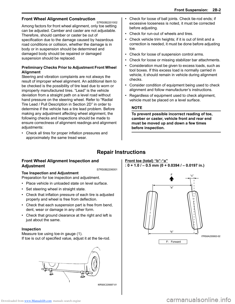
Measure toe using toe-in gauge (1).
If toe is out of specified value, adjust it at the tie-rod. Front toe (total) “b”-“a”
: 0 + 1.0 / – 0.5 mm (0 + 0.0394 / – 0.0197 in.)
I6RS0C220007-01
F: Forward
“a”
“c”
“b” F
I7RS0A220002-02
Page 436 of 1496
Downloaded from www.Manualslib.com manuals search engine 2B-3 Front Suspension:
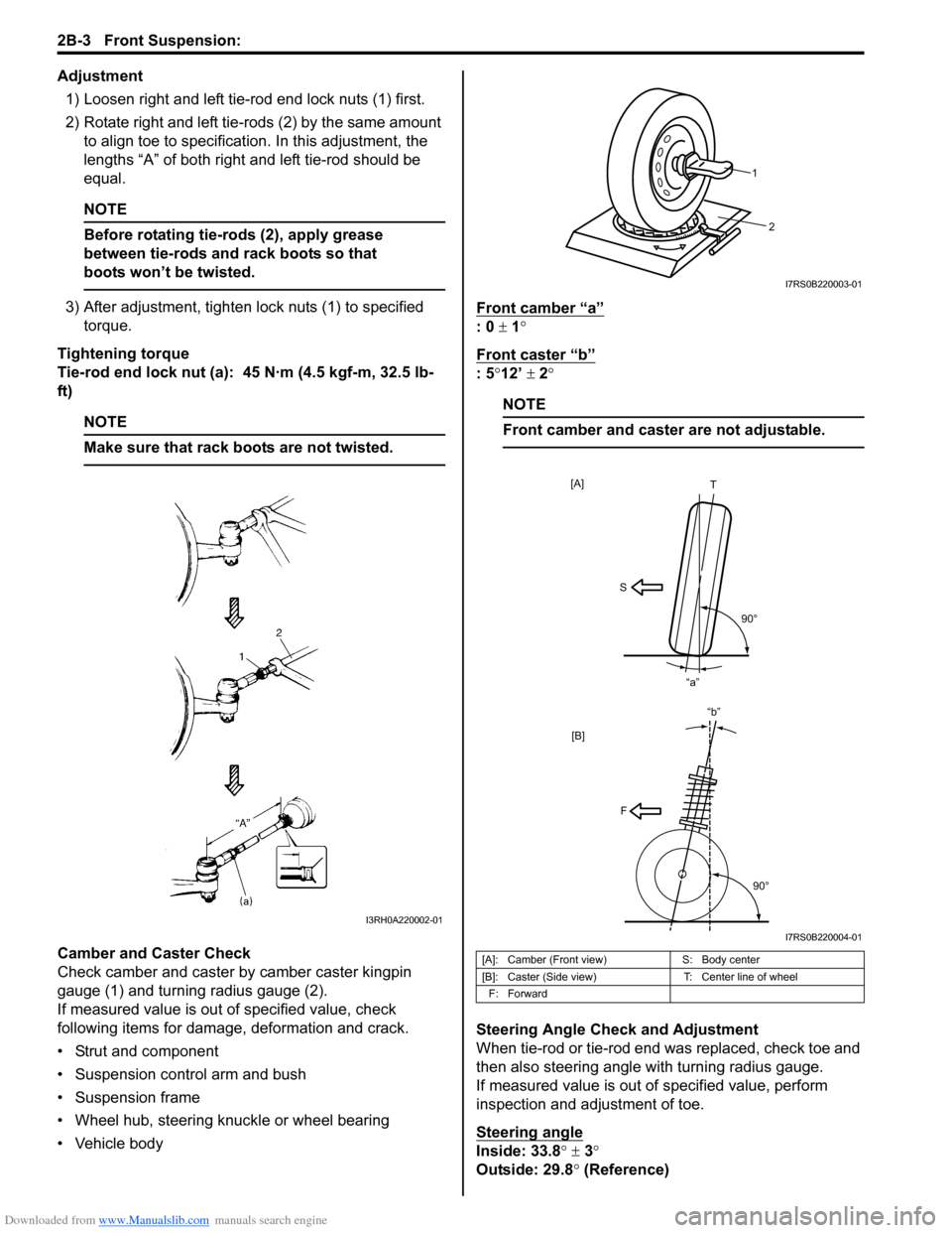
Adjustment1) Loosen right and left tie-rod end lock nuts (1) first.
2) Rotate right and left tie-rods (2) by the same amount to align toe to specification. In this adjustment, the
lengths “A” of both right and left tie-rod should be
equal.
NOTE
Before rotating tie-rods (2), apply grease
between tie-rods and rack boots so that
boots won’t be twisted.
3) After adjustment, tighten lock nuts (1) to specified torque.
Tightening torque
Tie-rod end lock nut (a): 45 N·m (4.5 kgf-m, 32.5 lb-
ft)
NOTE
Make sure that rack boots are not twisted.
Camber and Caster Check
Check camber and caster by camber caster kingpin
gauge (1) and turning radius gauge (2).
If measured value is out of specified value, check
following items for damage, deformation and crack.
• Strut and component
• Suspension control arm and bush
• Suspension frame
• Wheel hub, steering knuckle or wheel bearing
• Vehicle body Front camber “a”
: 0
± 1°
Front caster “b”
: 5 °12’ ± 2°
NOTE
Front camber and caster are not adjustable.
Steering Angle Check and Adjustment
When tie-rod or tie-rod end was replaced, check toe and
then also steering angle with turning radius gauge.
If measured value is out of specified value, perform
inspection and adjustment of toe.
Steering angle
Inside: 33.8 ° ± 3 °
Outside: 29.8 ° (Reference)
I3RH0A220002-01
[A]: Camber (Front view) S: Body center
[B]: Caster (Side view) T: Center line of wheel
F: Forward
2
1
I7RS0B220003-01
[B]
S T
90°
“a”
[A]
F
90°
“b”
I7RS0B220004-01
Page 456 of 1496
Downloaded from www.Manualslib.com manuals search engine 2C-2 Rear Suspension:
Repair Instructions
Rear Wheel Alignment InspectionS7RS0B2306017
Measure toe and camber referring to “Front Wheel
Alignment Inspection and Adjustment in Section 2B”.
NOTE
Rear suspension is not adjustable structure.
Rear toe (total)
: IN 3.8 ± 3.8 mm (IN 0.1969 ± 0.1969 in)
Rear camber
: –1 ° ± 1
If measured value is out of specified value, check
following items for damage, deformation and crack.
• Rear axle (torsion beam)
• Spindle, wheel hub or wheel bearing
• Vehicle body
Rear Shock Absorber Removal and InstallationS7RS0B2306001
Removal 1) Hoist vehicle and remove rear wheels.
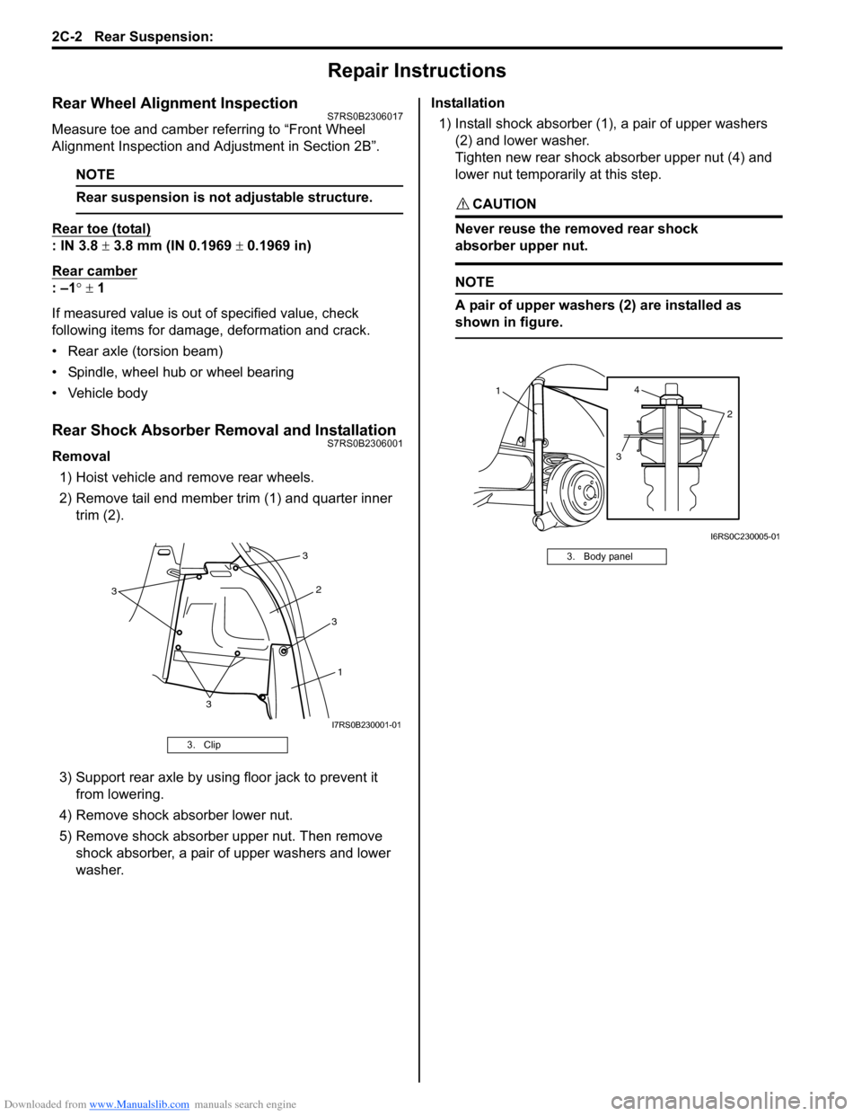
2) Remove tail end member trim (1) and quarter inner trim (2).
3) Support rear axle by using floor jack to prevent it from lowering.
4) Remove shock absorber lower nut.
5) Remove shock absorber upper nut. Then remove shock absorber, a pair of upper washers and lower
washer. Installation
1) Install shock absorber (1), a pair of upper washers (2) and lower washer.
Tighten new rear shock absorber upper nut (4) and
lower nut temporarily at this step.
CAUTION!
Never reuse the removed rear shock
absorber upper nut.
NOTE
A pair of upper washers (2) are installed as
shown in figure.
3. Clip
3
3 2
3
1
3
I7RS0B230001-01
3. Body panel
14
3 2
I6RS0C230005-01
Page 476 of 1496
Downloaded from www.Manualslib.com manuals search engine 2D-9 Wheels and Tires:
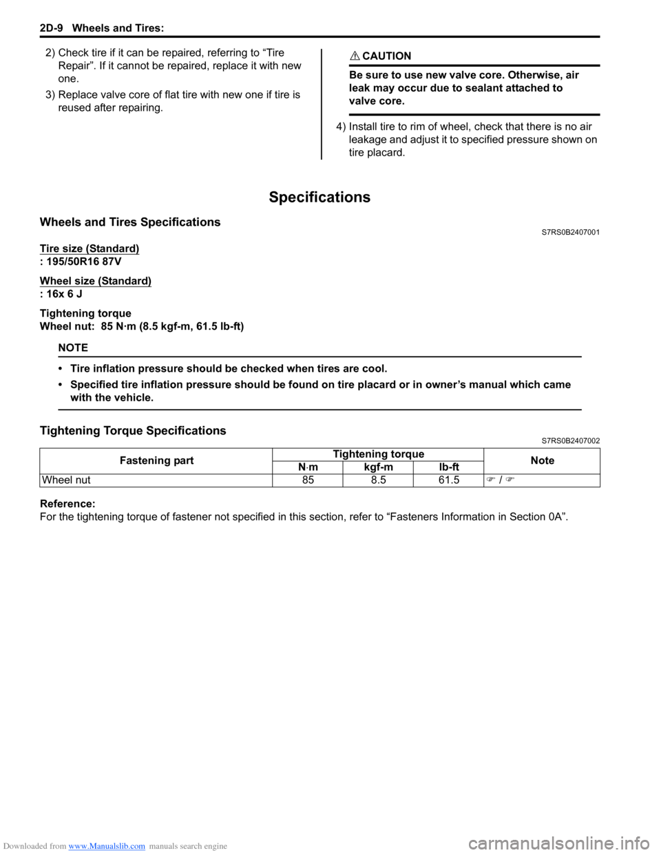
2) Check tire if it can be repaired, referring to “Tire
Repair”. If it cannot be repaired, replace it with new
one.
3) Replace valve core of flat tire with new one if tire is reused after repairing.CAUTION!
Be sure to use new valve core. Otherwise, air
leak may occur due to sealant attached to
valve core.
4) Install tire to ri m of wheel, check that there is no air
leakage and adjust it to specified pressure shown on
tire placard.
Specifications
Wheels and Tires SpecificationsS7RS0B2407001
Tire size (Standard)
: 195/50R16 87V
Wheel size (Standard)
: 16x 6 J
Tightening torque
Wheel nut: 85 N·m (8.5 kgf-m, 61.5 lb-ft)
NOTE
• Tire inflation pressure should be checked when tires are cool.
• Specified tire inflation pressure should be found on tire placard or in owner’s manual which came
with the vehicle.
Tightening Torque SpecificationsS7RS0B2407002
Reference:
For the tightening torque of fastener not specified in this section, refer to “Fasteners Information in Section 0A”.
Fastening part
Tightening torque
Note
N ⋅mkgf-mlb-ft
Wheel nut 858.5 61.5 �) / �)
Page 738 of 1496
Downloaded from www.Manualslib.com manuals search engine 5A-94 Automatic Transmission/Transaxle:
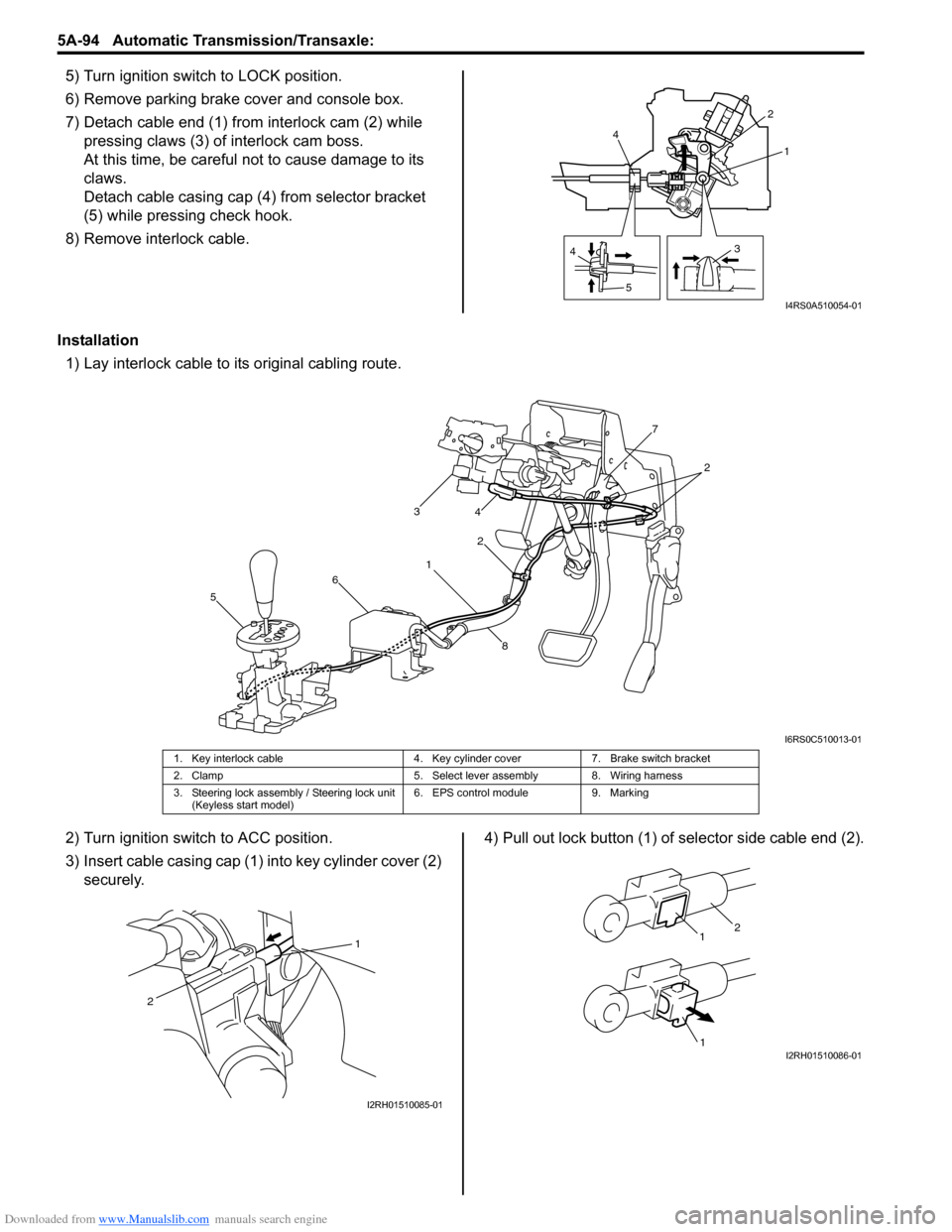
5) Turn ignition switch to LOCK position.
6) Remove parking brake cover and console box.
7) Detach cable end (1) from interlock cam (2) while
pressing claws (3) of interlock cam boss.
At this time, be careful no t to cause damage to its
claws.
Detach cable casing cap (4 ) from selector bracket
(5) while pressing check hook.
8) Remove interlock cable.
Installation 1) Lay interlock cable to its original cabling route.
2) Turn ignition switch to ACC position.
3) Insert cable casing cap (1) into key cylinder cover (2) securely. 4) Pull out lock button (1) of selector side cable end (2).
4
5 31
2
4
I4RS0A510054-01
1 2
3
4
5 6 7
8
2
I6RS0C510013-01
1. Key interlock cable 4. Key cylinder cover7. Brake switch bracket
2. Clamp 5. Select lever assembly 8. Wiring harness
3. Steering lock assembly / Steering lock unit (Keyless start model) 6. EPS control module
9. Marking
1
2
I2RH01510085-01
1
1
2
I2RH01510086-01