Front wheel SUZUKI SWIFT 2007 2.G Service Repair Manual
[x] Cancel search | Manufacturer: SUZUKI, Model Year: 2007, Model line: SWIFT, Model: SUZUKI SWIFT 2007 2.GPages: 1496, PDF Size: 34.44 MB
Page 520 of 1496
Downloaded from www.Manualslib.com manuals search engine 4B-4 Front Brakes:
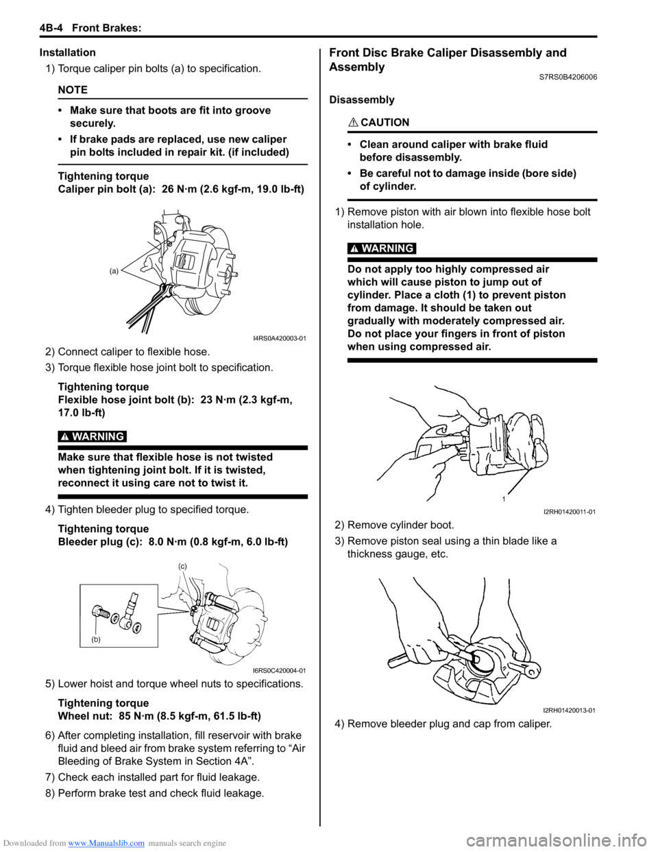
Installation1) Torque caliper pin bolts (a) to specification.
NOTE
• Make sure that boots are fit into groove securely.
• If brake pads are replaced, use new caliper pin bolts included in repair kit. (if included)
Tightening torque
Caliper pin bolt (a): 26 N·m (2.6 kgf-m, 19.0 lb-ft)
2) Connect caliper to flexible hose.
3) Torque flexible hose jo int bolt to specification.
Tightening torque
Flexible hose joint bolt (b): 23 N·m (2.3 kgf-m,
17.0 lb-ft)
WARNING!
Make sure that flexible hose is not twisted
when tightening joint bolt. If it is twisted,
reconnect it using care not to twist it.
4) Tighten bleeder plug to specified torque. Tightening torque
Bleeder plug (c): 8.0 N·m (0.8 kgf-m, 6.0 lb-ft)
5) Lower hoist and torque wheel nuts to specifications. Tightening torque
Wheel nut: 85 N·m (8.5 kgf-m, 61.5 lb-ft)
6) After completing installation, fill reservoir with brake
fluid and bleed air from brake system referring to “Air
Bleeding of Brake System in Section 4A”.
7) Check each installed part for fluid leakage.
8) Perform brake test and check fluid leakage.
Front Disc Brake Caliper Disassembly and
Assembly
S7RS0B4206006
Disassembly
CAUTION!
• Clean around caliper with brake fluid before disassembly.
• Be careful not to damage inside (bore side) of cylinder.
1) Remove piston with air blown into flexible hose bolt installation hole.
WARNING!
Do not apply too highly compressed air
which will cause piston to jump out of
cylinder. Place a cloth (1) to prevent piston
from damage. It should be taken out
gradually with moderately compressed air.
Do not place your fingers in front of piston
when using compressed air.
2) Remove cylinder boot.
3) Remove piston seal using a thin blade like a thickness gauge, etc.
4) Remove bleeder plug and cap from caliper.
(a)
I4RS0A420003-01
I6RS0C420004-01
I2RH01420011-01
I2RH01420013-01
Page 522 of 1496
Downloaded from www.Manualslib.com manuals search engine 4B-6 Front Brakes:
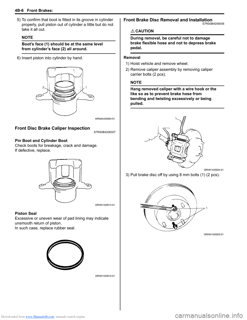
5) To confirm that boot is fitted in its groove in cylinder
properly, pull piston out of cylinder a little but do not
take it all out.
NOTE
Boot’s face (1) should be at the same level
from cylinder’s face (2) all around.
6) Insert piston into cylinder by hand.
Front Disc Brake Caliper InspectionS7RS0B4206007
Pin Boot and Cylinder Boot
Check boots for breakage, crack and damage.
If defective, replace.
Piston Seal
Excessive or uneven wear of pad lining may indicate
unsmooth return of piston.
In such case, replace rubber seal.
Front Brake Disc Removal and InstallationS7RS0B4206008
CAUTION!
During removal, be care ful not to damage
brake flexible hose and not to depress brake
pedal.
Removal
1) Hoist vehicle and remove wheel.
2) Remove caliper assembly by removing caliper carrier bolts (2 pcs).
NOTE
Hang removed caliper with a wire hook or the
like so as to prevent brake hose from
bending and twisting excessively or being
pulled.
3) Pull brake disc off by using 8 mm bolts (1) (2 pcs).
I4RS0A420004-01
I2RH01420014-01
I2RH01420015-01
I2RH01420024-01
I2RH01420025-01
Page 523 of 1496
Downloaded from www.Manualslib.com manuals search engine Front Brakes: 4B-7
Installation1) Install disc to wheel hub.
2) Install caliper assemb ly to steering knuckle.
3) Torque caliper carrier bolts to specification.
Tightening torque
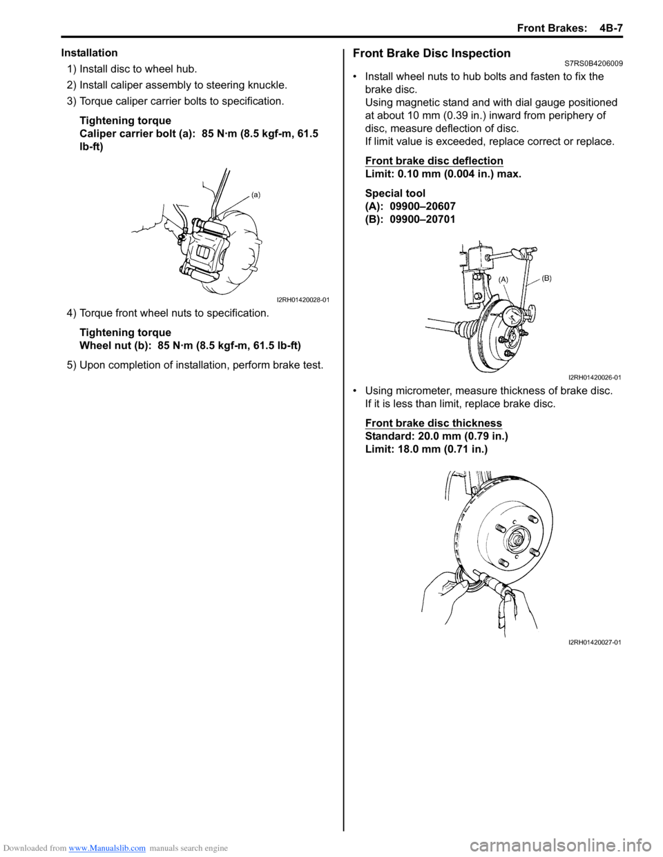
Caliper carrier bolt (a): 85 N·m (8.5 kgf-m, 61.5
lb-ft)
4) Torque front wheel nuts to specification. Tightening torque
Wheel nut (b): 85 N·m (8.5 kgf-m, 61.5 lb-ft)
5) Upon completion of installation, perform brake test.Front Brake Disc InspectionS7RS0B4206009
• Install wheel nuts to hub bolts and fasten to fix the brake disc.
Using magnetic stand and with dial gauge positioned
at about 10 mm (0.39 in.) inward from periphery of
disc, measure deflection of disc.
If limit value is exceeded, replace correct or replace.
Front brake disc deflection
Limit: 0.10 mm (0.004 in.) max.
Special tool
(A): 09900–20607
(B): 09900–20701
• Using micrometer, measure thickness of brake disc. If it is less than limit, replace brake disc.
Front brake disc thickness
Standard: 20.0 mm (0.79 in.)
Limit: 18.0 mm (0.71 in.)
I2RH01420028-01
I2RH01420026-01
I2RH01420027-01
Page 524 of 1496
Downloaded from www.Manualslib.com manuals search engine 4B-8 Front Brakes:
Specifications
Tightening Torque SpecificationsS7RS0B4207001
NOTE
The specified tightening torque is also described in the following.
“Front Disc Brake Components”
Reference:
For the tightening torque of fastener not specified in this section, refer to “Fasteners Information in Section 0A”.
Special Tools and Equipment
Recommended Service MaterialS7RS0B4208001
NOTE
Required service material is also described in the following.
“Front Disc Brake Components”
Special ToolS7RS0B4208002
Fastening part Tightening torque
Note
N ⋅mkgf-mlb-ft
Caliper pin bolt 26 2.6 19.0 �) / �)
Wheel nut 85 8.5 61.5 �) / �) / �)
Flexible hose joint bolt 23 2.3 17.0 �)
Bleeder plug 8.0 0.8 6.0 �)
Caliper carrier bolt 85 8.5 61.5 �)
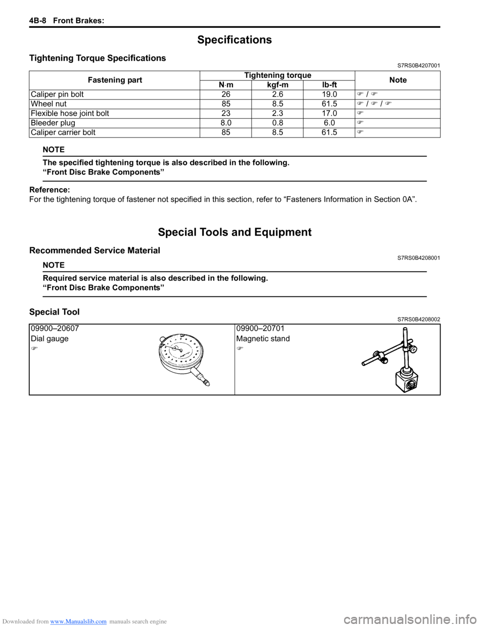
09900–2060709900–20701
Dial gauge Magnetic stand
�)�)
Page 541 of 1496
Downloaded from www.Manualslib.com manuals search engine ABS: 4E-2
General Description
ABS DescriptionS7RS0B4501001
The ABS (Antilock Brake System) controls the fluid
pressure applied to the wheel cylinder of each brake
from the master cylinder so that each wheel is not locked
even when hard braking is applied.
This ABS has also the following function.
While braking is applied, but before ABS control
becomes effective, braking force is distributed between
the front and rear so as to prevent the rear wheels from
being locked too early for better stability of the vehicle.
The main component parts of this ABS include the
following parts in addition to those of the conventional
brake system.
• Wheel speed sensor which senses revolution speed of each wheel and outputs its signal.
• ABS warning light which light s to inform abnormality
when system fails to operate properly.
• ABS hydraulic unit / cont rol module assembly is
incorporated ABS co ntrol module, ABS hydraulic unit
(actuator assembly), solenoid valve power supply
driver (transistor), solenoid valve driver (transistor),
pump motor driver (transistor).
– ABS control module which sends operation signal to ABS hydraulic unit to control fluid pressure
applied to each wheel cylinder based on signal
from each wheel speed sensor so as to prevent
wheel from locking.
– ABS hydraulic unit which operates according to signal from ABS control module to control fluid
pressure applied to wheel cylinder of each 4
wheels.
– Solenoid valve power supp ly driver (transistor)
which supplies power to solenoid valve in ABS
hydraulic unit.
– Solenoid valve driver (transistor) which controls each solenoid valves in ABS hydraulic unit.
– Pump motor driver (transistor) which supplies power to pump motor in ABS hydraulic unit.
This ABS is equipped with Electronic Brake force
Distribution (EBD) system that controls a fluid pressure
of rear wheels to best condition, which is the same
function as that of proportion ing valve, by the signal from
wheel sensor independently of change of load due to
load capacity and so on. An d if the EBD system fails to
operate properly, the brake warning light lights to inform
abnormality.
ABS Hydraulic Unit / Control Module Assembly
Description
S7RS0B4501002
ABS control module is a component of ABS hydraulic
unit / control module asse mbly and has the following
functions.
Self-Diagnosis Function
ABS control module diagnose s conditions of the system
component parts (whether or not there is any
abnormality) all the time and indicates the results
(warning of abnormality occurrence and DTC) through
the ABS warning light as described.
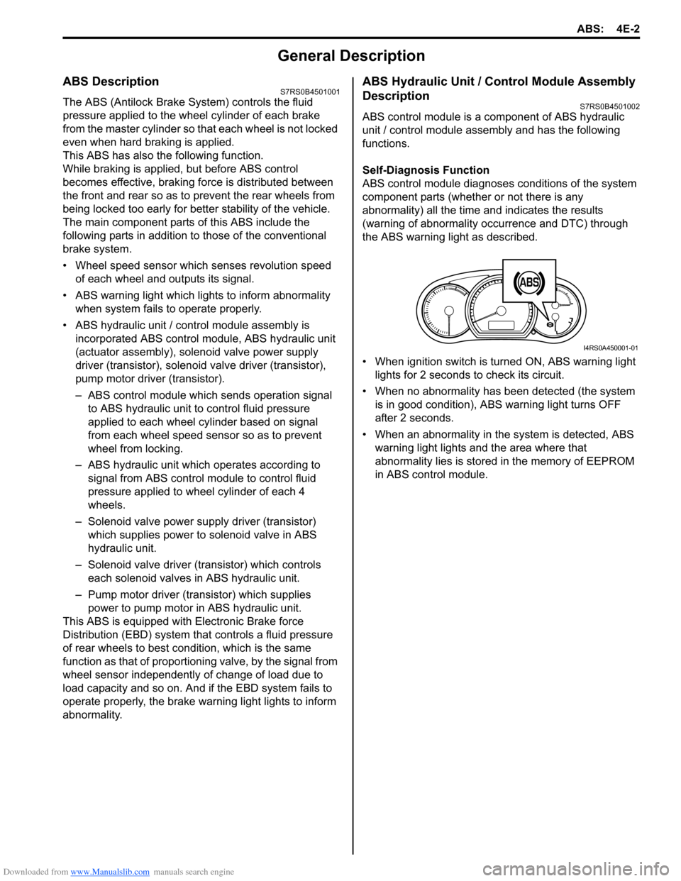
• When ignition switch is turned ON, ABS warning light lights for 2 seconds to check its circuit.
• When no abnormality has been detected (the system is in good condition), ABS warning light turns OFF
after 2 seconds.
• When an abnormality in th e system is detected, ABS
warning light lights and the area where that
abnormality lies is stored in the memory of EEPROM
in ABS control module.
1
I4RS0A450001-01
Page 542 of 1496
Downloaded from www.Manualslib.com manuals search engine 4E-3 ABS:
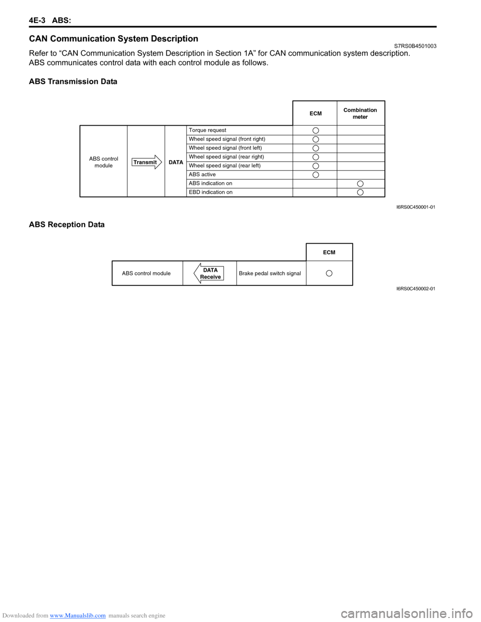
CAN Communication System DescriptionS7RS0B4501003
Refer to “CAN Communication System Description in Section 1A” for CAN communication system description.
ABS communicates control data with each control module as follows.
ABS Transmission Data
ABS Reception Data
Combination
meter
Transmit DATA
ABS control
moduleECM
Torque request
Wheel speed signal (front right)
Wheel speed signal (front left)
Wheel speed signal (rear right)
Wheel speed signal (rear left)
ABS active
ABS indication on
EBD indication on
I6RS0C450001-01
ABS control moduleDATA
Receive
ECM
Brake pedal switch signal
I6RS0C450002-01
Page 544 of 1496
Downloaded from www.Manualslib.com manuals search engine 4E-5 ABS:
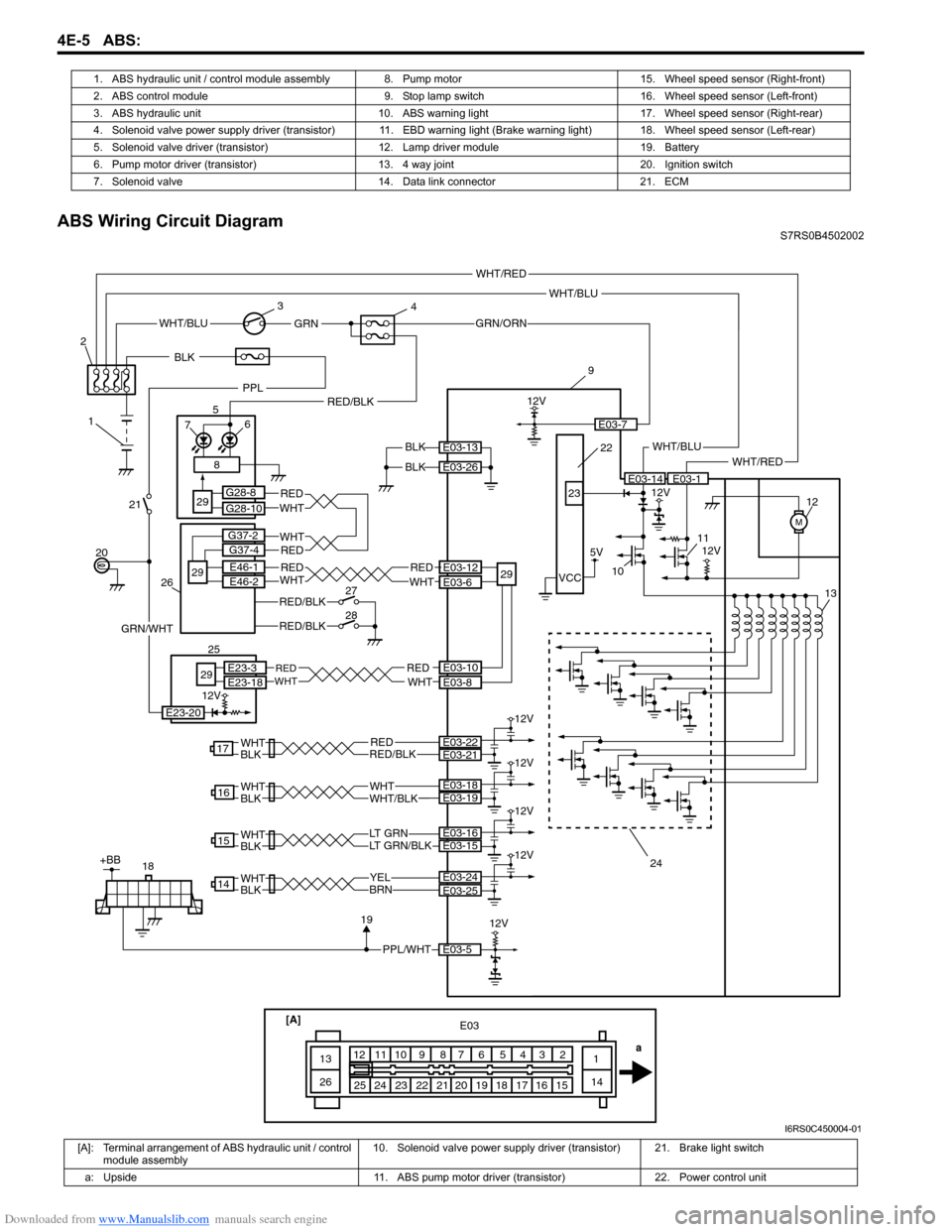
ABS Wiring Circuit DiagramS7RS0B4502002
1. ABS hydraulic unit / control module assembly 8.
Pump motor 15. Wheel speed sensor (Right-front)
2. ABS control module 9. Stop lamp switch 16. Wheel speed sensor (Left-front)
3. ABS hydraulic unit 10. ABS warning light 17. Wheel speed sensor (Right-rear)
4. Solenoid valve power supply driver (transistor) 11. EBD warnin g light (Brake warning light) 18. Wheel speed sensor (Left-rear)
5. Solenoid valve driver (transistor) 12. Lamp driver module 19. Battery
6. Pump motor driver (transistor) 13. 4 way joint 20. Ignition switch
7. Solenoid valve 14. Data link connector 21. ECM
[A]
14
1516171819202122232425 1
23456789101112
13
26 E03
a
WHT/BLU
BLKWHT/BLU
M
12V
9
10 11 12
13
BLKE03-14E03-1
E03-13
E03-26
YELBRN
14E03-24
LT GRN/BLKLT GRN
15
WHTWHT/BLK
16
RED
WHTBLK
WHTBLK
WHTBLK
WHTBLKRED/BLK
17
12V
PPL/WHT
18E03-5
1912V
5V
12V
23
24
VCC22
E03-25
E03-15E03-16
E03-19E03-18
E03-22E03-21
WHT/RED
WHT/RED
+BB
GRN/ORN
E03-7
WHT/BLUGRN
1
2
3
4
8
RED/BLK
E03-12
E03-6
RED
WHTE03-10E03-8
REDWHT
20 7
6
529
29
G28-8
G28-10
25
29
E23-3E23-18
GRN/WHT
21
PPL
12V
E23-20
12V
12V
12V
12V
REDWHTE46-1
E46-2
BLK
RED/BLK
RED/BLK
RED
RED
WHT
WHT
27
28
26
29
G37-2
G37-4
REDWHT
I6RS0C450004-01
[A]: Terminal arrangement of ABS hydraulic unit / control module assembly 10. Solenoid valve power supply driver
(transistor) 21. Brake light switch
a: Upside 11. ABS pump motor driver (transistor) 22. Power control unit
Page 545 of 1496
Downloaded from www.Manualslib.com manuals search engine ABS: 4E-6
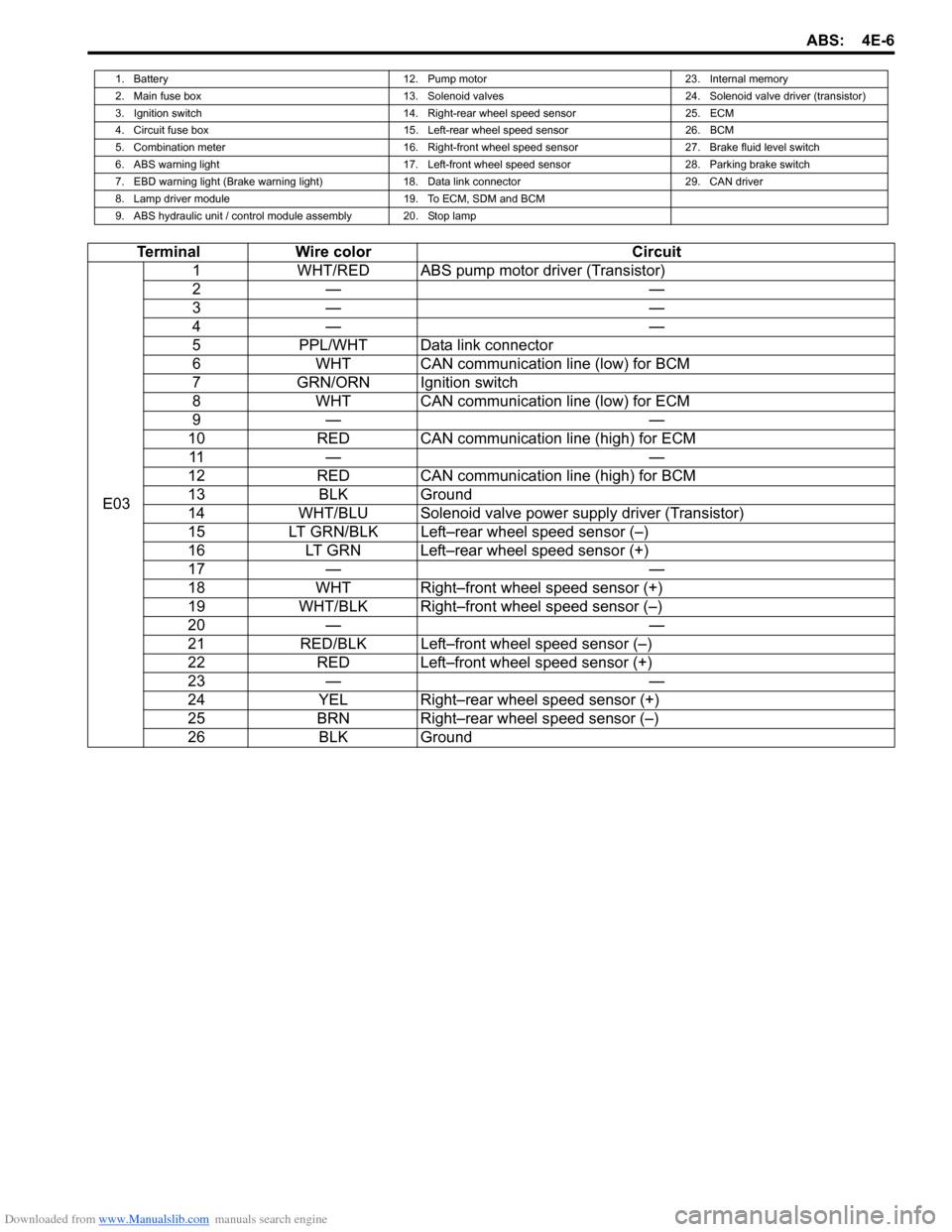
1. Battery12. Pump motor23. Internal memory
2. Main fuse box 13. Solenoid valves24. Solenoid valve driver (transistor)
3. Ignition switch 14. Right-rear wheel speed sensor25. ECM
4. Circuit fuse box 15. Left-rear wheel speed sensor26. BCM
5. Combination meter 16. Right-front wheel speed sensor27. Brake fluid level switch
6. ABS warning light 17. Left-front wheel speed sensor28. Parking brake switch
7. EBD warning light (Brake warning light) 18. Data link connector29. CAN driver
8. Lamp driver module 19. To ECM, SDM and BCM
9. ABS hydraulic unit / control module assembly 20. Stop lamp
Terminal Wire color Circuit
E03 1
WHT/RED ABS pump motor driver (Transistor)
2— —
3— —
4— —
5 PPL/WHT Data link connector
6 WHT CAN communication line (low) for BCM
7 GRN/ORN Ignition switch
8 WHT CAN communication line (low) for ECM
9— —
10 RED CAN communication line (high) for ECM
11 — —
12 RED CAN communication line (high) for BCM
13 BLK Ground
14 WHT/BLU Solenoid valve power supply driver (Transistor)
15 LT GRN/BLK Left–rear wheel speed sensor (–)
16 LT GRN Left–rear wheel speed sensor (+)
17 — —
18 WHT Right–front wheel speed sensor (+)
19 WHT/BLK Right–front wheel speed sensor (–)
20 — —
21 RED/BLK Left–front wheel speed sensor (–)
22 RED Left–front wheel speed sensor (+)
23 — —
24 YEL Right–rear wheel speed sensor (+)
25 BRN Right–rear wheel speed sensor (–)
26 BLK Ground
Page 546 of 1496
Downloaded from www.Manualslib.com manuals search engine 4E-7 ABS:
Component Location
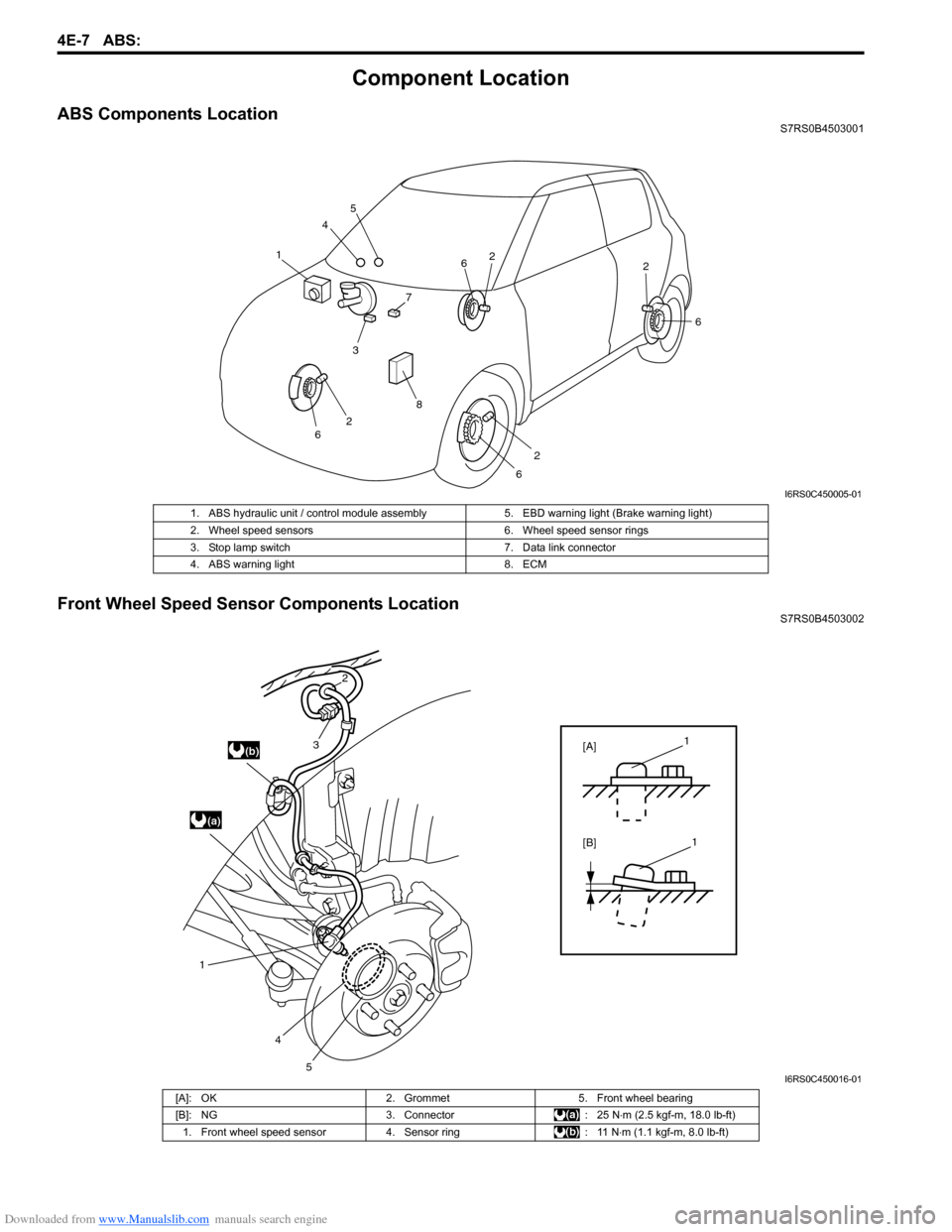
ABS Components LocationS7RS0B4503001
Front Wheel Speed Sensor Components LocationS7RS0B4503002
14
5
3
2 2
2
2
6
6
6
6
7
8
I6RS0C450005-01
1. ABS hydraulic unit / control module assembly
5. EBD warning light (Brake warning light)
2. Wheel speed sensors 6. Wheel speed sensor rings
3. Stop lamp switch 7. Data link connector
4. ABS warning light 8. ECM
[A]
[B]
1 1
2
3
4
1
(a)
(b)
5I6RS0C450016-01
[A]: OK 2. Grommet5. Front wheel bearing
[B]: NG 3. Connector: 25 N⋅m (2.5 kgf-m, 18.0 lb-ft)
1. Front wheel speed sensor 4. Sensor ring: 11 N⋅m (1.1 kgf-m, 8.0 lb-ft)
Page 557 of 1496
Downloaded from www.Manualslib.com manuals search engine ABS: 4E-18
DTC C1021, C1022 / C1025, C1026 / C1031, C1032 / C1035, C1036: Right-Front / Left-Front / Right-
Rear / Left-Rear Wheel Speed Sensor Circuit or Sensor Ring
S7RS0B4504012
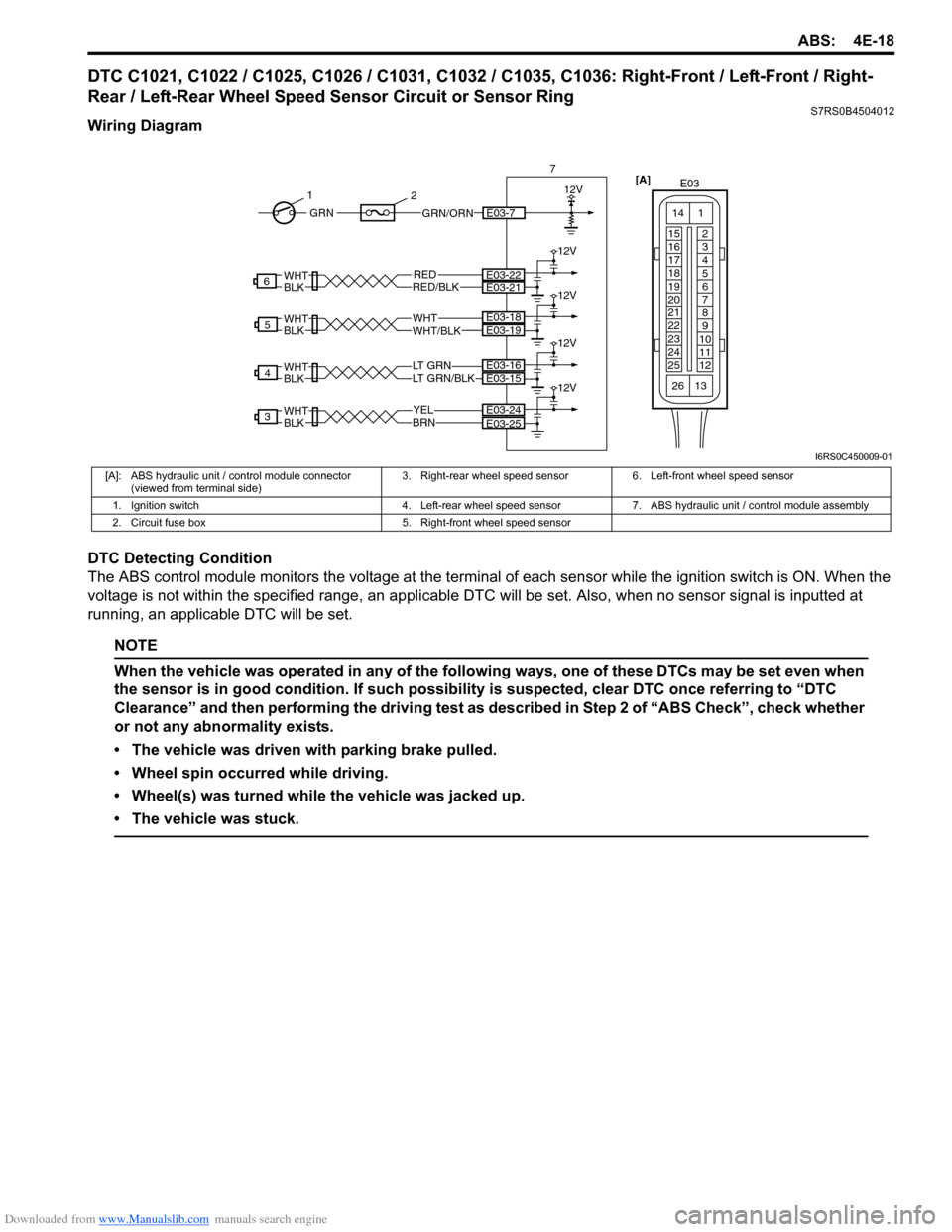
Wiring Diagram
DTC Detecting Condition
The ABS control module monitors the voltage at the terminal of each sensor while the ignition swit ch is ON. When the
voltage is not within the specified range, an applicable DTC will be set. Also, when no sensor signal is inputted at
running, an applicable DTC will be set.
NOTE
When the vehicle was operated in any of the following ways, one of these DTCs may be set even when
the sensor is in good condition. If such possibility is suspected, clear DTC once referring to “DTC
Clearance” and then performing the driving test as described in Step 2 of “ABS Check”, check whether
or not any abnormality exists.
• The vehicle was driven with parking brake pulled.
• Wheel spin occurred while driving.
• Wheel(s) was turned while the vehicle was jacked up.
• The vehicle was stuck.
YELBRN
3E03-24
LT GRN/BLKLT GRN
4
WHTWHT/BLK
5
RED
WHTBLK
WHTBLK
WHTBLK
WHTBLKRED/BLK
6
E03-25
E03-15E03-16
E03-19E03-18
E03-22E03-21
12V
12V
12V
12V
12V
7
GRN/ORNE03-7GRN
1
2
[A]
E03
15
16
17
18
19
20
21
22
23
24
25 2
3
4
5
6
7
8
9
10
11
12
1
13
14
26
I6RS0C450009-01
[A]: ABS hydraulic unit / control module connector
(viewed from terminal side) 3. Right-rear wheel speed sensor 6. Left-front wheel speed sensor
1. Ignition switch 4. Left-rear wheel speed sensor 7. ABS hydraulic unit / control module assembly
2. Circuit fuse box 5. Right-front wheel speed sensor