air SUZUKI SWIFT 2007 2.G Service Workshop Manual
[x] Cancel search | Manufacturer: SUZUKI, Model Year: 2007, Model line: SWIFT, Model: SUZUKI SWIFT 2007 2.GPages: 1496, PDF Size: 34.44 MB
Page 1329 of 1496
Downloaded from www.Manualslib.com manuals search engine Glass / Windows / Mirrors: 9E-2
• Eyeleteer
• Piano string
• Windshield knife
• Brush for primer application (2 pcs)
•Knife
• Rubber sucker grip
• Sealant gun (for filling adhesive)
• Putty spatula (for correcting adhered parts)
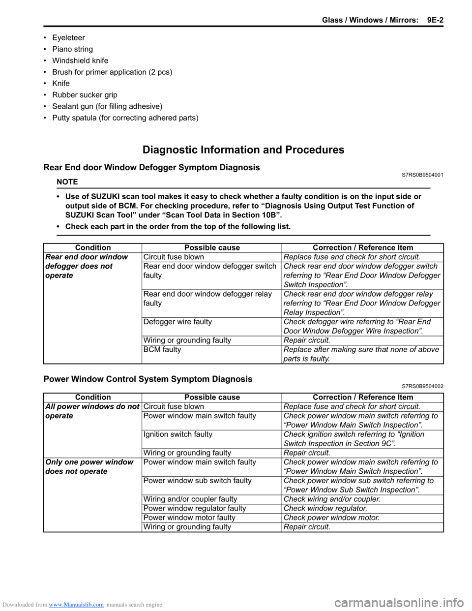
Diagnostic Information and Procedures
Rear End door Window Defogger Symptom DiagnosisS7RS0B9504001
NOTE
• Use of SUZUKI scan tool makes it easy to check whether a faulty condition is on the input side or
output side of BCM. For checking procedure, re fer to “Diagnosis Using Output Test Function of
SUZUKI Scan Tool” under “Scan Tool Data in Section 10B”.
• Check each part in the order from the top of the following list.
Power Window Control System Symptom DiagnosisS7RS0B9504002
Condition Possible cause Correction / Reference Item
Rear end door window
defogger does not
operate Circuit fuse blown
Replace fuse and check for short circuit.
Rear end door window defogger switch
faulty Check rear end door window defogger switch
referring to “Rear End Door Window Defogger
Switch Inspection”.
Rear end door window defogger relay
faulty Check rear end door window defogger relay
referring to “Rear End Door Window Defogger
Relay Inspection”.
Defogger wire faulty Check defogger wire referring to “Rear End
Door Window Defogger Wire Inspection”.
Wiring or grounding faulty Repair circuit.
BCM faulty Replace after making sure that none of above
parts is faulty.
ConditionPossible cause Correction / Reference Item
All power windows do not
operate Circuit fuse blown
Replace fuse and check for short circuit.
Power window main switch faulty Check power window main switch referring to
“Power Window Main Switch Inspection”.
Ignition switch faulty Check ignition switch referring to “Ignition
Switch Inspection in Section 9C”.
Wiring or grounding faulty Repair circuit.
Only one power window
does not operate Power window main switch faulty
Check power window main switch referring to
“Power Window Main Switch Inspection”.
Power window sub switch faulty Check power window sub switch referring to
“Power Window Sub Switch Inspection”.
Wiring and/or coupler faulty Check wiring and/or coupler.
Power window regulator faulty Check window regulator.
Power window motor faulty Check power window motor.
Wiring or grounding faulty Repair circuit.
Page 1330 of 1496
Downloaded from www.Manualslib.com manuals search engine 9E-3 Glass / Windows / Mirrors:
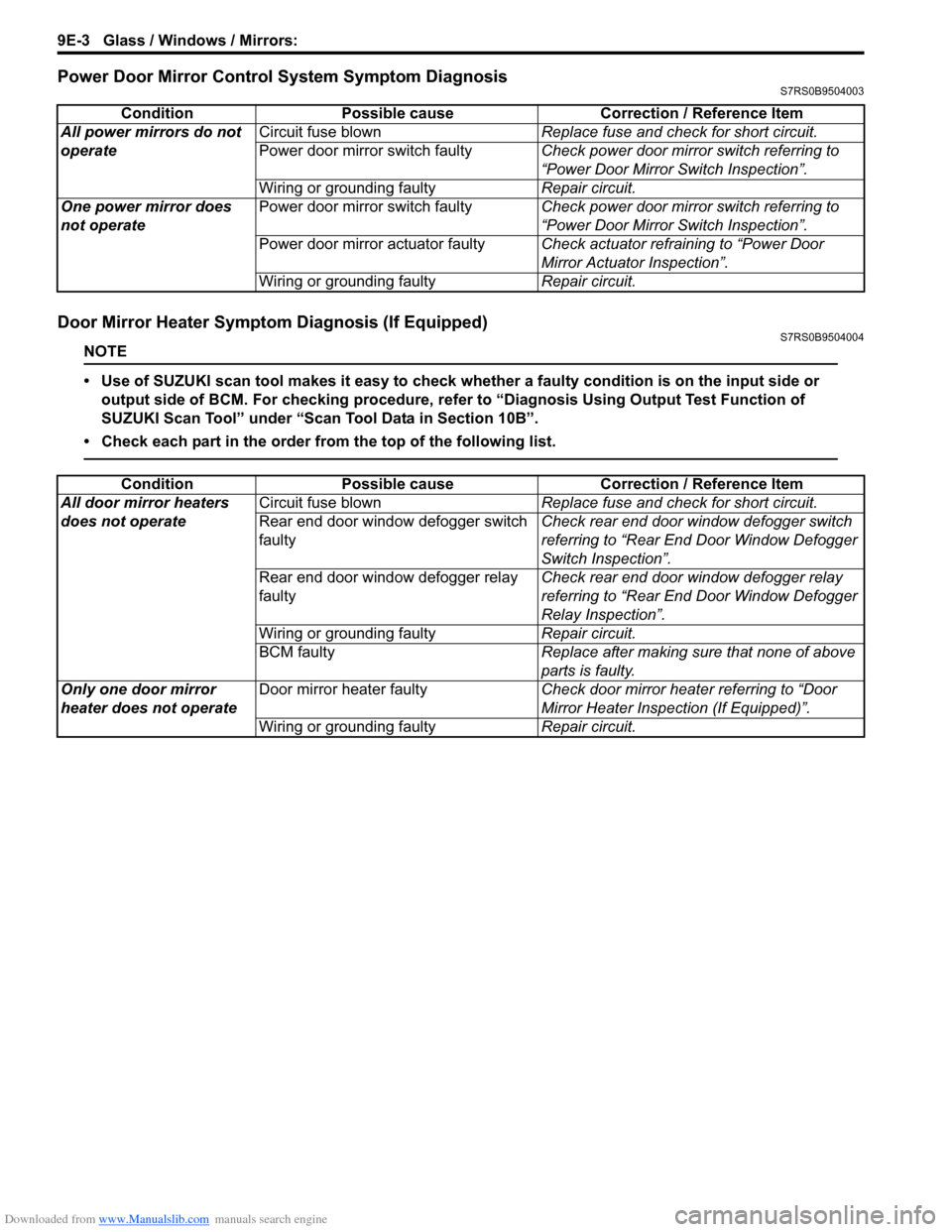
Power Door Mirror Control System Symptom DiagnosisS7RS0B9504003
Door Mirror Heater Symptom Diagnosis (If Equipped)S7RS0B9504004
NOTE
• Use of SUZUKI scan tool makes it easy to check whether a faulty condition is on the input side or
output side of BCM. For checking procedure, re fer to “Diagnosis Using Output Test Function of
SUZUKI Scan Tool” under “Scan Tool Data in Section 10B”.
• Check each part in the order from the top of the following list.
Condition Possible cause Correction / Reference Item
All power mirrors do not
operate Circuit fuse blown
Replace fuse and check for short circuit.
Power door mirror switch faulty Check power door mirror switch referring to
“Power Door Mirror Switch Inspection”.
Wiring or grounding faulty Repair circuit.
One power mirror does
not operate Power door mirror switch faulty
Check power door mirror switch referring to
“Power Door Mirror Switch Inspection”.
Power door mirror actuator faulty Check actuator refraining to “Power Door
Mirror Actuator Inspection”.
Wiring or grounding faulty Repair circuit.
ConditionPossible cause Correction / Reference Item
All door mirror heaters
does not operate Circuit fuse blown
Replace fuse and check for short circuit.
Rear end door window defogger switch
faulty Check rear end door window defogger switch
referring to “Rear End Door Window Defogger
Switch Inspection”.
Rear end door window defogger relay
faulty Check rear end door window defogger relay
referring to “Rear End Door Window Defogger
Relay Inspection”.
Wiring or grounding faulty Repair circuit.
BCM faulty Replace after making sure that none of above
parts is faulty.
Only one door mirror
heater does not operate Door mirror heater faulty
Check door mirror heater referring to “Door
Mirror Heater Inspection (If Equipped)”.
Wiring or grounding faulty Repair circuit.
Page 1331 of 1496
Downloaded from www.Manualslib.com manuals search engine Glass / Windows / Mirrors: 9E-4
Repair Instructions
Windshield Removal and InstallationS7RS0B9506001
Removal1) Clean both inside and outside of glass and around it.
2) Remove wiper arms and cowl top garnish.
3) Remove windshield side garnish.
4) Using tape, cover body surface around glass to prevent any damage.
5) Remove rear view mirror , sun visor and front pillar
trims (right & left).
6) If necessary, remove instrument panel. Refer to “Instrument Panel Removal and Installation in
Section 9C”.
7) If necessary, remove he ad lining. Refer to “Head
Lining Removal and Installation in Section 9H”.
8) Remove (or cut) windshield molding.
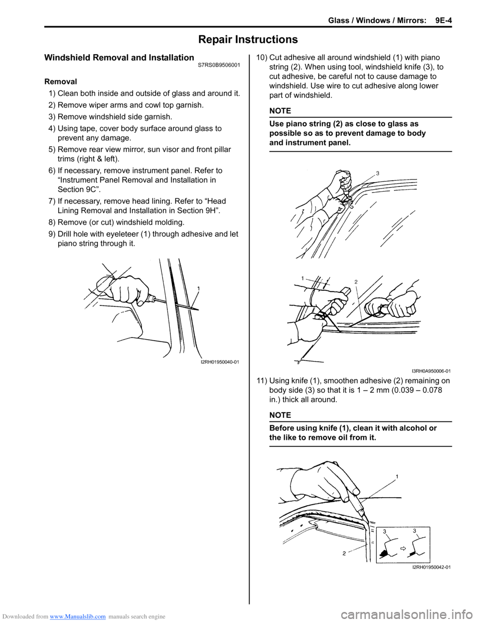
9) Drill hole with eyeleteer (1 ) through adhesive and let
piano string through it. 10) Cut adhesive all around windshield (1) with piano
string (2). When using tool, windshield knife (3), to
cut adhesive, be careful not to cause damage to
windshield. Use wire to cut adhesive along lower
part of windshield.
NOTE
Use piano string (2) as close to glass as
possible so as to prevent damage to body
and instrument panel.
11) Using knife (1), smoothen adhesive (2) remaining on body side (3) so that it is 1 – 2 mm (0.039 – 0.078
in.) thick all around.
NOTE
Before using knife (1), clean it with alcohol or
the like to remove oil from it.
I2RH01950040-01
I3RH0A950006-01
I2RH01950042-01
Page 1334 of 1496
Downloaded from www.Manualslib.com manuals search engine 9E-7 Glass / Windows / Mirrors:
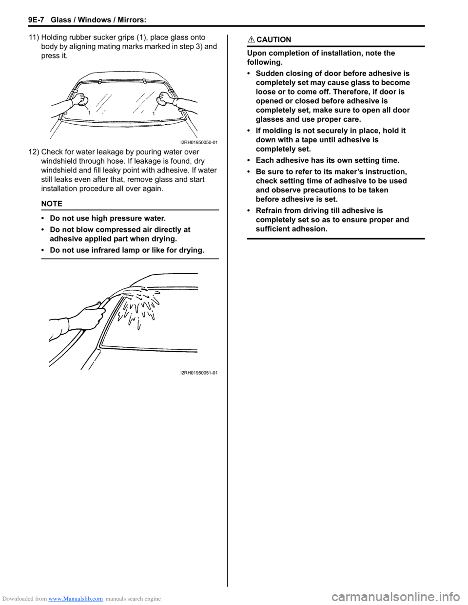
11) Holding rubber sucker grips (1), place glass onto body by aligning mating marks marked in step 3) and
press it.
12) Check for water leakage by pouring water over windshield through hose. If leakage is found, dry
windshield and fill leaky po int with adhesive. If water
still leaks even after that , remove glass and start
installation procedure all over again.
NOTE
• Do not use high pressure water.
• Do not blow compressed air directly at adhesive applied part when drying.
• Do not use infrared lamp or like for drying.
CAUTION!
Upon completion of installation, note the
following.
• Sudden closing of door before adhesive is completely set may cause glass to become
loose or to come off. Therefore, if door is
opened or closed before adhesive is
completely set, make sure to open all door
glasses and use proper care.
• If molding is not securely in place, hold it down with a tape until adhesive is
completely set.
• Each adhesive has its own setting time.
• Be sure to refer to its maker’s instruction, check setting time of adhesive to be used
and observe precautions to be taken
before adhesive is set.
• Refrain from driving till adhesive is completely set so as to ensure proper and
sufficient adhesion.
I2RH01950050-01
I2RH01950051-01
Page 1342 of 1496
Downloaded from www.Manualslib.com manuals search engine 9E-15 Glass / Windows / Mirrors:
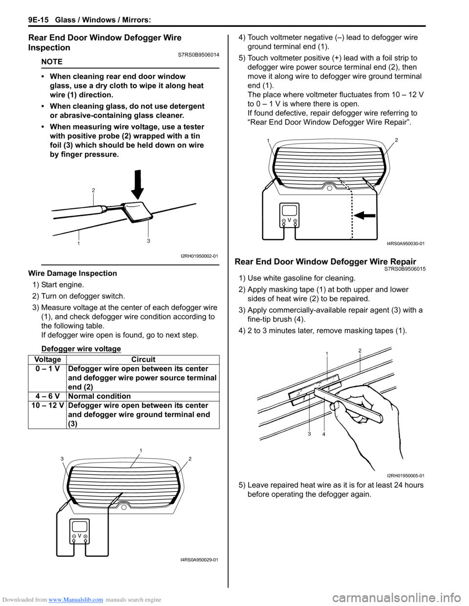
Rear End Door Window Defogger Wire
Inspection
S7RS0B9506014
NOTE
• When cleaning rear end door window glass, use a dry cloth to wipe it along heat
wire (1) direction.
• When cleaning glass, do not use detergent or abrasive-containing glass cleaner.
• When measuring wire voltage, use a tester with positive probe (2) wrapped with a tin
foil (3) which should be held down on wire
by finger pressure.
Wire Damage Inspection
1) Start engine.
2) Turn on defogger switch.
3) Measure voltage at the center of each defogger wire (1), and check defogger wire condition according to
the following table.
If defogger wire open is found, go to next step.
Defogger wire voltage
4) Touch voltmeter negative (–) lead to defogger wire ground terminal end (1).
5) Touch voltmeter positive (+) lead with a foil strip to defogger wire power source terminal end (2), then
move it along wire to defogger wire ground terminal
end (1).
The place where voltmeter fluctuates from 10 – 12 V
to 0 – 1 V is where there is open.
If found defective, repair defogger wire referring to
“Rear End Door Window Defogger Wire Repair”.
Rear End Door Window Defogger Wire RepairS7RS0B9506015
1) Use white gasoline for cleaning.
2) Apply masking tape (1) at both upper and lower sides of heat wire (2) to be repaired.
3) Apply commercially-available repair agent (3) with a fine-tip brush (4).
4) 2 to 3 minutes later, remove masking tapes (1).
5) Leave repaired heat wire as it is for at least 24 hours before operating the defogger again.
Voltage Circuit
0 – 1 V Defogger wire open between its center and defogger wire power source terminal
end (2)
4 – 6 V Normal condition
10 – 12 V Defogger wire open between its center and defogger wire ground terminal end
(3)
I2RH01950002-01
2
1
3
I4RS0A950029-01
21
I4RS0A950030-01
I2RH01950005-01
Page 1349 of 1496
Downloaded from www.Manualslib.com manuals search engine Security and Locks: 9F-3
Diagnostic Information and Procedures
Power Door Lock System Symptom DiagnosisS7RS0B9604001
NOTE
• Use of SUZUKI scan tool makes it easy to check whether a faulty condition is on the input side or
output side of BCM. For checking procedure, re fer to “Diagnosis Using Output Test Function of
SUZUKI Scan Tool” under “Scan Tool Data in Section 10B”.
• Check each part in the order from the top of the following list.
Power Door Lock System Operation InspectionS7RS0B9604002
1) Check the following operation:
a) Turn the driver side key cylinder is turned LOCK once, check all doors lock.
b) Turn the driver side door key cylinder is turned UNLOC K position with door key twice, check all doors unlock.
If malfunction is found, go to “Power Door Lock System Symptom Diagnosis”.
Condition Possible cause Correction / Reference Item
All door can not be locked
/ unlocked by all of
switches Circuit fuse blown
Replace fuse and check for short circuit.
Wiring or grounding faulty Repair circuit.
BCM faulty Replace after making sure that none of above
parts is faulty.
All door can not be locked
/ unlocked by only power
door lock switch Circuit fuse blown
Replace fuse and check for short circuit.
Power door lock switch faulty Check power door lock switch referring to
“Power Door Lock Switch Inspection”.
Wiring harness connected to power door
lock switch faulty Repair.
Wiring or grounding faulty Repair circuit.
BCM faulty Replace after making sure that none of above
parts is faulty.
All door can not be locked
/ unlocked by only key
cylinder switch Circuit fuse blown
Replace fuse and check for short circuit.
Key cylinder switch faulty Check key cylinder switch referring to “Door
Key Cylinder Switch Inspection”.
Wiring or grounding faulty Repair circuit.
BCM faulty Replace after making sure that none of above
parts is faulty.
Only one door can not be
locked / unlocked Power door lock actuator faulty
Check actuator referring to “Power Door Lock
Actuator Inspection”.
Wiring harness connected to applicable
door lock actuator faulty Repair.
BCM faulty Replace after making sure that none of above
parts is faulty.
Page 1350 of 1496
Downloaded from www.Manualslib.com manuals search engine 9F-4 Security and Locks:
Keyless Entry System Symptom Diagnosis (If Equipped)S7RS0B9604003
NOTE
• Confirm that power door lock system is in good condition before referring to the following possible causes.
• Check each part in the order from the top of the following list.
Condition Possible cause Correction / Reference Item
All door can not be locked
/ unlocked by only
keyless entry transmitter Transmitter battery dead
Replace battery referring to “Replacement of
Transmitter Battery”.
Door switch faulty Check door switch referring to “Door Switch
(Front / Rear Door) Inspection in Section 9C”
and/or “Rear End Door Switch Inspection in
Section 9C”.
Transmitter faulty Replace transmitter.
Key reminder switch in ignition switch
faulty Check ignition switch referring to “Ignition
Switch Inspection in Section 9C”.
Wiring or grounding faulty Repair circuit.
Keyless entry receiver faulty Check keyless entry receiver referring to
“Keyless Entry Receiver and Its Circuit
Inspection”.
BCM faulty Replace after making sure that none of above
parts is faulty.
Interior light does not
light when doors are
unlocked by keyless entry
transmitter Wiring or grounding faulty
Repair circuit.
BCM faulty Replace after making sure that none of above
parts is faulty.
Hazard warning lights do
not light when doors are
locked/unlocked by
keyless entry transmitter Turn signal and hazard warning relay
faulty
Check turn signal and hazard warning relay
referring to “Turn Signal and Hazard Warning
Relay Inspection in Section 9B”.
Wiring or grounding faulty Repair circuit.
BCM faulty Replace after making sure that none of above
parts is faulty.
Transmitter code can not
be programmed to BCM Door switch faulty
Check door switch referring to “Door Switch
(Front / Rear Door) Inspection in Section 9C”
and/or “Rear End Door Switch Inspection in
Section 9C”.
Keyless entry receiver faulty Check keyless entry receiver referring to
“Keyless Entry Receiver and Its Circuit
Inspection”.
Key reminder switch in ignition switch
faulty Check ignition switch referring to “Ignition
Switch Inspection in Section 9C”.
Wiring or grounding faulty Repair circuit.
BCM faulty Replace after making sure that none of above
parts is faulty.
Page 1351 of 1496
Downloaded from www.Manualslib.com manuals search engine Security and Locks: 9F-5
Keyless Entry System Operation InspectionS7RS0B9604004
NOTE
When performing the this inspection, make
sure to have any of the door once opened/
closed after the ignition key has been
removed from the ignition key cylinder.
1) Confirm that power door lock system operates normally, refer to “Power Door Lock System
Operation Inspection”.
2) All doors are closed and unlocked.
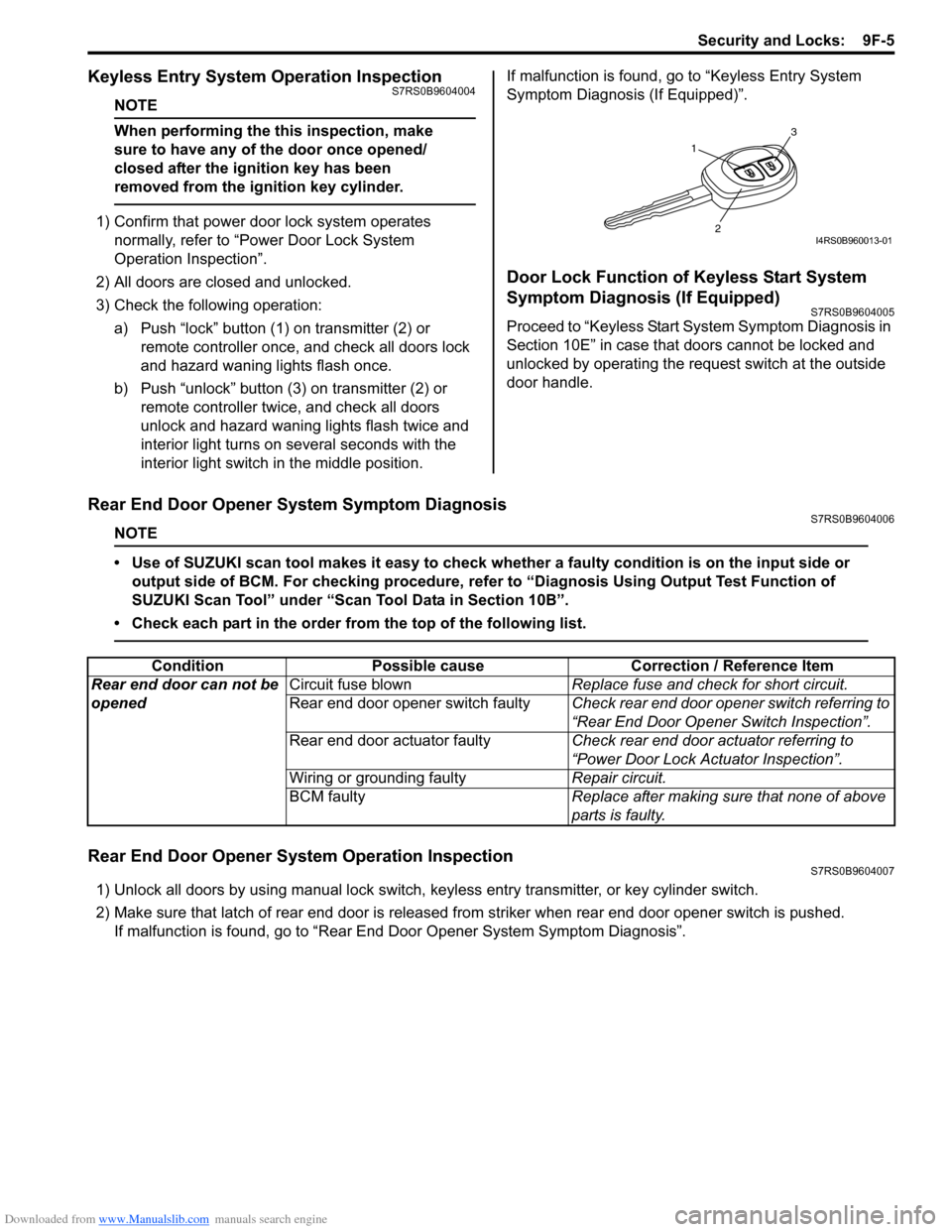
3) Check the following operation: a) Push “lock” button (1 ) on transmitter (2) or
remote controller once, and check all doors lock
and hazard waning lights flash once.
b) Push “unlock” button (3) on transmitter (2) or remote controller twice, and check all doors
unlock and hazard waning lights flash twice and
interior light turns on several seconds with the
interior light switch in the middle position. If malfunction is found, go to “Keyless Entry System
Symptom Diagnosis (If Equipped)”.
Door Lock Function of Keyless Start System
Symptom Diagnosis (If Equipped)
S7RS0B9604005
Proceed to “Keyless Start System Symptom Diagnosis in
Section 10E” in case that doors cannot be locked and
unlocked by operating the request switch at the outside
door handle.
Rear End Door Opener System Symptom DiagnosisS7RS0B9604006
NOTE
• Use of SUZUKI scan tool makes it easy to check wh
ether a faulty condition is on the input side or
output side of BCM. For checking procedure, re fer to “Diagnosis Using Output Test Function of
SUZUKI Scan Tool” under “Scan Tool Data in Section 10B”.
• Check each part in the order from the top of the following list.
Rear End Door Opener System Operation InspectionS7RS0B9604007
1) Unlock all doors by using manu al lock switch, keyless entry transmitter, or key cylinder switch.
2) Make sure that latch of rear end door is released from striker when rear end door opener switch is pushed. If malfunction is found, go to “Rear End Door Opener System Symptom Diagnosis”.
1
3
2I4RS0B960013-01
ConditionPossible cause Correction / Reference Item
Rear end door can not be
opened Circuit fuse blown
Replace fuse and check for short circuit.
Rear end door opener switch faulty Check rear end door opener switch referring to
“Rear End Door Opener Switch Inspection”.
Rear end door actuator faulty Check rear end door actuator referring to
“Power Door Lock Actuator Inspection”.
Wiring or grounding faulty Repair circuit.
BCM faulty Replace after making sure that none of above
parts is faulty.
Page 1352 of 1496
Downloaded from www.Manualslib.com manuals search engine 9F-6 Security and Locks:
Repair Instructions
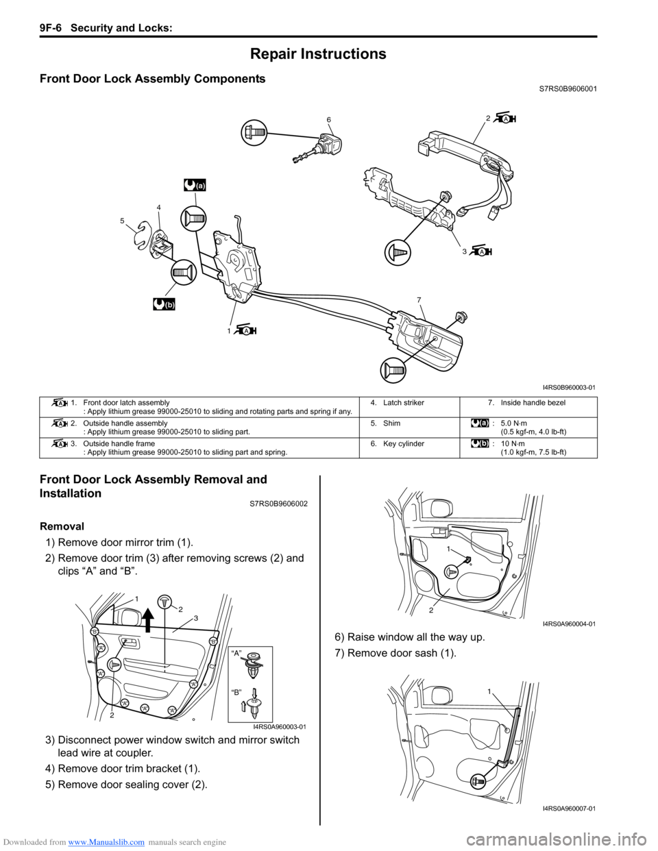
Front Door Lock Assembly ComponentsS7RS0B9606001
Front Door Lock Assembly Removal and
Installation
S7RS0B9606002
Removal1) Remove door mirror trim (1).
2) Remove door trim (3) after removing screws (2) and clips “A” and “B”.
3) Disconnect power window s witch and mirror switch
lead wire at coupler.
4) Remove door trim bracket (1).
5) Remove door sealing cover (2). 6) Raise window all the way up.
7) Remove door sash (1).
(a)
(b)
6
3
7
1
4
5
2
I4RS0B960003-01
1. Front door latch assembly : Apply lithium grease 99000-25010 to sliding and rotating parts and spring if any. 4. Latch striker 7. Inside handle bezel
2. Outside handle assembly : Apply lithium grease 99000-25010 to sliding part. 5. Shim : 5.0 N
⋅m
(0.5 kgf-m, 4.0 lb-ft)
3. Outside handle frame : Apply lithium grease 99000-25010 to sliding part and spring. 6. Key cylinder : 10 N⋅m
(1.0 kgf-m, 7.5 lb-ft)
“B”
“A”
“B”
“A”
“B”“A”
“A”
“A”“A”“A”
12
2 3
I4RS0A960003-01
1
2
I4RS0A960004-01
1
I4RS0A960007-01
Page 1363 of 1496
Downloaded from www.Manualslib.com manuals search engine Seats: 9G-1
Body, Cab and Accessories
Seats
Repair Instructions
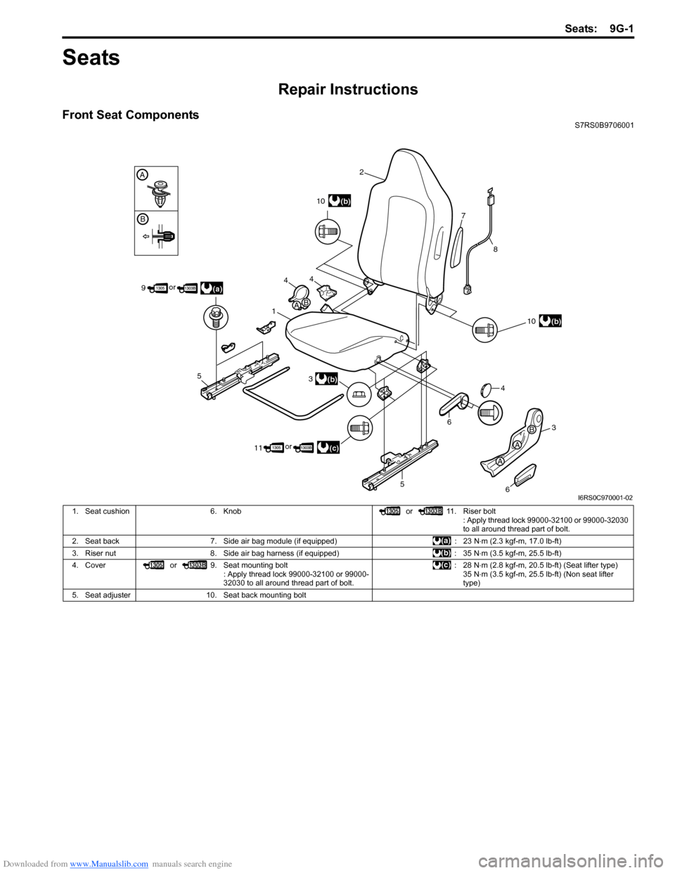
Front Seat ComponentsS7RS0B9706001
2
4
1 3
11
6
3
4
6
7
8
(b)
(b)
10
5
(a)
or
94
5
(c)
(b)
10
or
A
A
B
AB
B
A
I6RS0C970001-02
1. Seat cushion 6. Knob or 11. Riser bolt
: Apply thread lock 99000-32100 or 99000-32030
to all around thread part of bolt.
2. Seat back 7. Side air bag module (if equipped) : 23 N⋅m (2.3 kgf-m, 17.0 lb-ft)
3. Riser nut 8. Side air bag harness (if equipped) : 35 N⋅m (3.5 kgf-m, 25.5 lb-ft)
4. Cover or 9. Seat mounting bolt
: Apply thread lock 99000-32100 or 99000-
32030 to all around thread part of bolt. :28 N
⋅m (2.8 kgf-m, 20.5 lb-ft) (Seat lifter type)
35 N ⋅m (3.5 kgf-m, 25.5 lb-ft) (Non seat lifter
type)
5. Seat adjuster 10. Seat back mounting bolt