starting system SUZUKI SWIFT 2007 2.G Service Manual Online
[x] Cancel search | Manufacturer: SUZUKI, Model Year: 2007, Model line: SWIFT, Model: SUZUKI SWIFT 2007 2.GPages: 1496, PDF Size: 34.44 MB
Page 1116 of 1496
Downloaded from www.Manualslib.com manuals search engine 8B-78 Air Bag System:
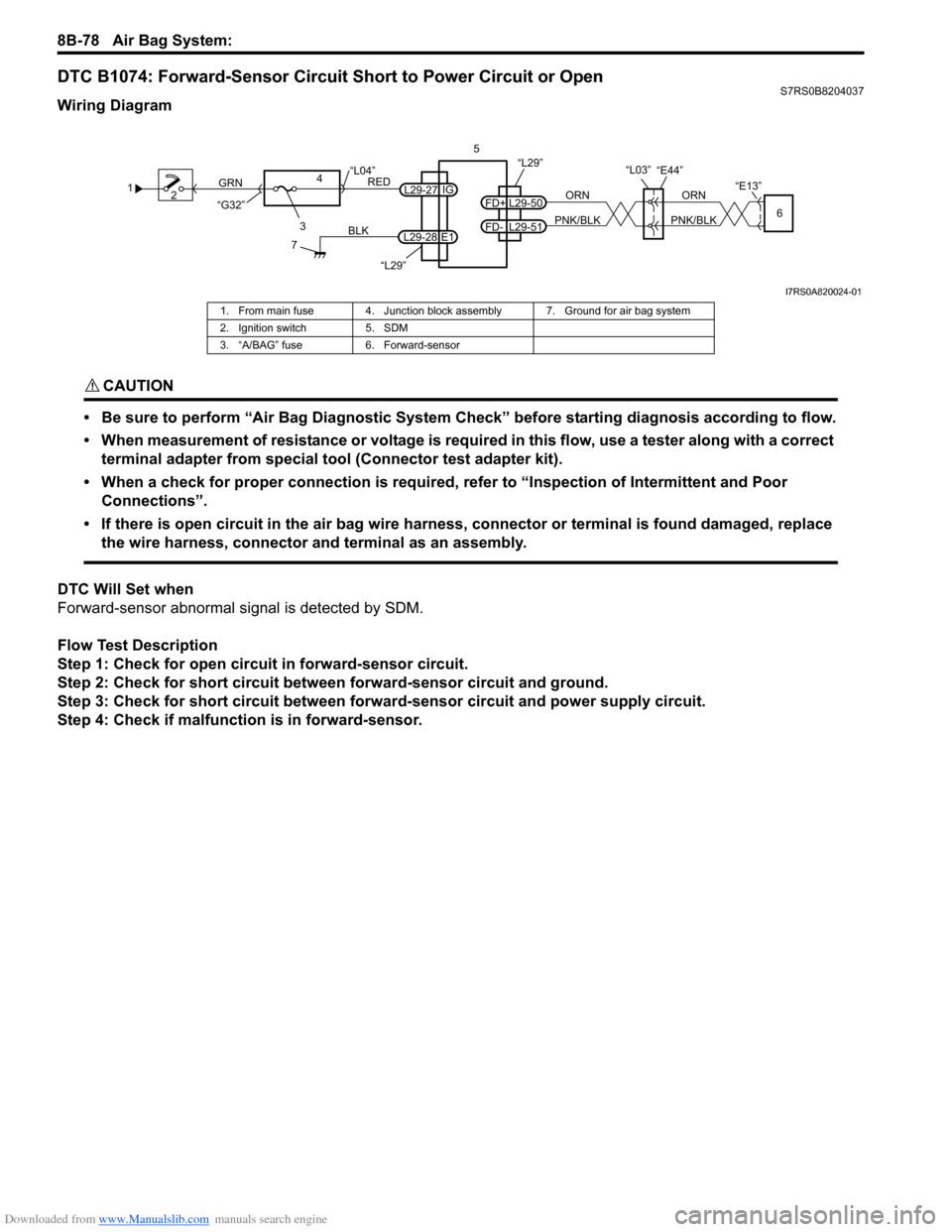
DTC B1074: Forward-Sensor Circuit Short to Power Circuit or OpenS7RS0B8204037
Wiring Diagram
CAUTION!
• Be sure to perform “Air Bag Diagnostic System Check” before starting diagnosis according to flow.
• When measurement of resistance or voltage is required in this flow, use a tester along with a correct terminal adapter from special tool (Connector test adapter kit).
• When a check for proper connection is required, refer to “Inspection of Intermittent and Poor Connections”.
• If there is open circuit in the air bag wire harnes s, connector or terminal is found damaged, replace
the wire harness, connector and terminal as an assembly.
DTC Will Set when
Forward-sensor abnormal signal is detected by SDM.
Flow Test Description
Step 1: Check for open circuit in forward-sensor circuit.
Step 2: Check for short circuit between forward-sensor circuit and ground.
Step 3: Check for short circuit between forw ard-sensor circuit and power supply circuit.
Step 4: Check if malfuncti on is in forward-sensor.
1
2
3
GRN
RED
7
BLK
L29-27
L29-28 IG
E1
4
“L29”
“L04”
“G32”
“L29”5
ORN
PNK/BLK
ORN
PNK/BLKL29-50
FD+
L29-51
FD-6
“E13”
“L03”“E44”
I7RS0A820024-01
1. From main fuse 4. Junction block assembly 7. Ground for air bag system
2. Ignition switch 5. SDM
3. “A/BAG” fuse 6. Forward-sensor
Page 1118 of 1496
Downloaded from www.Manualslib.com manuals search engine 8B-80 Air Bag System:
DTC B1081 / B1091: Driver / Passenger Side-Sensor Performance ProblemS7RS0B8204038
DTC Will Set when
SDM receives internal fault signal from side-sensor.
DTC Troubleshooting1) Turn ignition switch OFF.
2) Replace driver or passenger side-sensor referr ing to “Side-Sensor Removal and Installation”.
3) Repeat “Air Bag Diagnostic System Check”.
DTC B1082 / B1092: Driver / Passenger Side-Sensor Communication ErrorS7RS0B8204039
DTC Will Set when
Side-sensor abnormal signal is detected by SDM.
DTC Troubleshooting
1) Turn ignition switch OFF.
2) Replace driver or passenger side-sensor referr ing to “Side-Sensor Removal and Installation”.
3) Repeat “Air Bag Diagnostic System Check”.
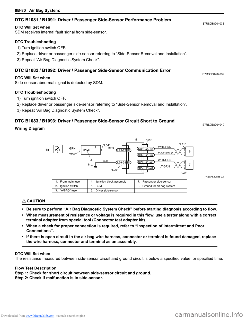
DTC B1083 / B1093: Driver / Passenger Side-Sensor Circuit Short to GroundS7RS0B8204040
Wiring Diagram
CAUTION!
• Be sure to perform “Air Bag Diagnostic System Check” before starting diagnosis according to flow.
• When measurement of resistance or voltage is required in this flow, use a tester along with a correct terminal adapter from special tool (Connector test adapter kit).
• When a check for proper connection is required, refer to “Inspection of Intermittent and Poor Connections”.
• If there is open circuit in the air bag wire harnes s, connector or terminal is found damaged, replace
the wire harness, connector and terminal as an assembly.
DTC Will Set when
The resistance measured between side-sen sor circuit and ground circuit is below a specified value for specified time.
Flow Test Description
Step 1: Check for short circuit between side-sensor circuit and ground.
Step 2: Check if malfunction is in side-sensor.
1 2
3
GRN
RED
8
BLK
L29-27
L29-28 IG
E1
4
“L29”
“L04”
“G32”
“L29”5
WHT/RED
LT GRN/BLKL29-46
SD+
L29-47
SD-6
“L11”
WHT/GRN
LT GRNL29-45
SP+
L29-44
SP-7
“L35”
I7RS0A820028-02
1. From main fuse 4. Junction blo ck assembly 7. Passenger side-sensor
2. Ignition switch 5. SDM 8. Ground for air bag system
3. “A/BAG” fuse 6. Driver side-sensor
Page 1120 of 1496
Downloaded from www.Manualslib.com manuals search engine 8B-82 Air Bag System:
CAUTION!
• Be sure to perform “Air Bag Diagnostic System Check” before starting diagnosis according to flow.
• When measurement of resistance or voltage is required in this flow, use a tester along with a correct terminal adapter from special tool (Connector test adapter kit).
• When a check for proper connection is required, refer to “Inspection of Intermittent and Poor Connections”.
• If there is open circuit in the air bag wire harnes s, connector or terminal is found damaged, replace
the wire harness, connector and terminal as an assembly.
DTC Will Set when
The resistance measured between side-sensor circuit and power source circuit is below a specified value for specified
time.
Flow Test Description
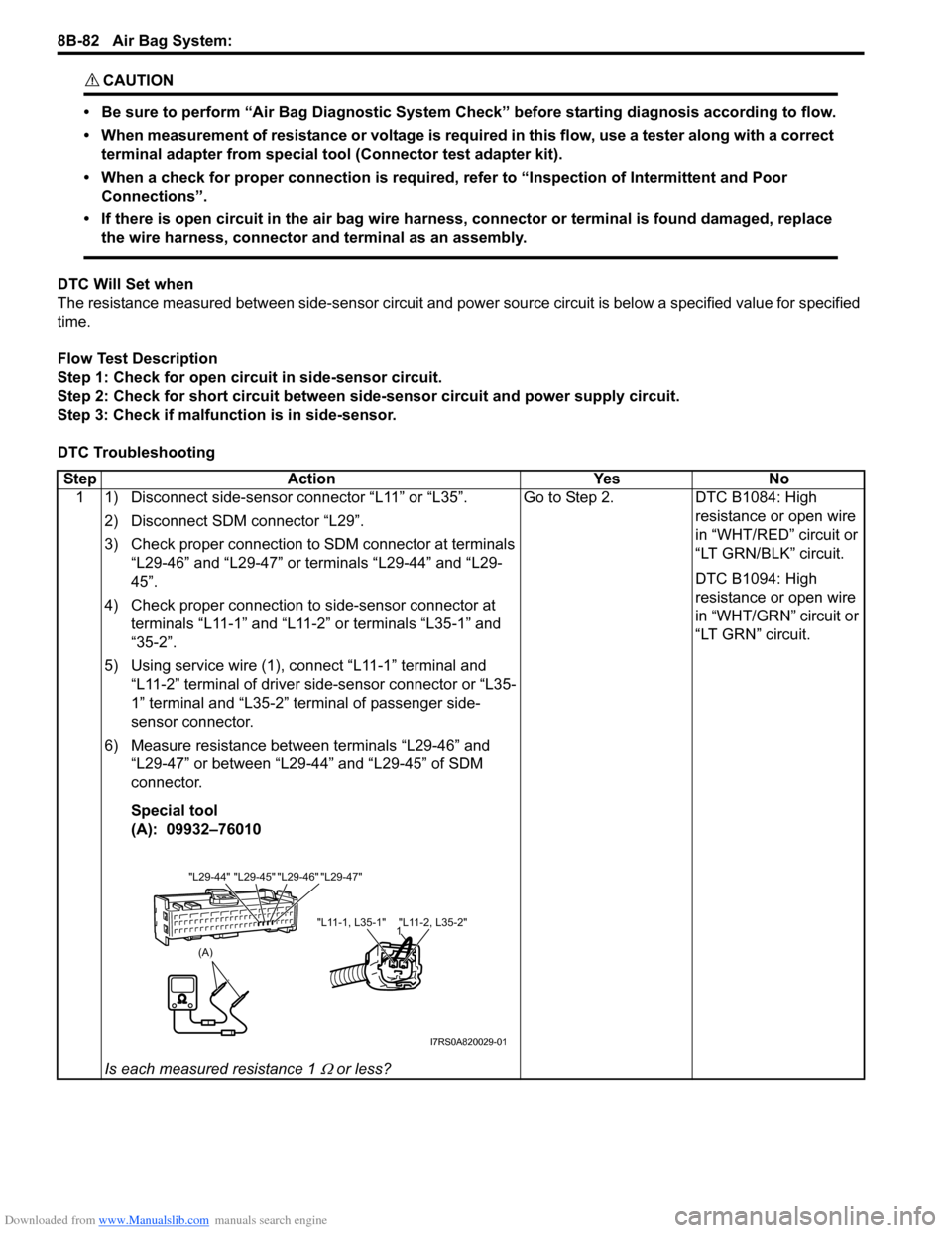
Step 1: Check for open circuit in side-sensor circuit.
Step 2: Check for short circuit between side-sensor circuit and power supply circuit.
Step 3: Check if malfunction is in side-sensor.
DTC Troubleshooting
Step Action YesNo
1 1) Disconnect side-sensor connector “L11” or “L35”.
2) Disconnect SDM connector “L29”.
3) Check proper connection to SDM connector at terminals “L29-46” and “L29-47” or terminals “L29-44” and “L29-
45”.
4) Check proper connection to side-sensor connector at terminals “L11-1” and “L11-2” or terminals “L35-1” and
“35-2”.
5) Using service wire (1), connect “L11-1” terminal and “L11-2” terminal of driver side-sensor connector or “L35-
1” terminal and “L35-2” terminal of passenger side-
sensor connector.
6) Measure resistance between terminals “L29-46” and “L29-47” or between “L29-44” and “L29-45” of SDM
connector.
Special tool
(A): 09932–76010
Is each measured resistance 1
Ω or less? Go to Step 2. DTC B1084: High
resistance or open wire
in “WHT/RED” circuit or
“LT GRN/BLK” circuit.
DTC B1094: High
resistance or open wire
in “WHT/GRN” circuit or
“LT GRN” circuit.
(A)
"L11-1, L35-1" "L11-2, L35-2"1
"L29-45" "L29-46" "L29-47"
"L29-44"
I7RS0A820029-01
Page 1122 of 1496

Downloaded from www.Manualslib.com manuals search engine 8B-84 Air Bag System:
DTC B1361 / B1365: Driver / Passenger Side Curtain-Air Bag Initiator Circuit Resistance HighS7RS0B8204043
Wiring Diagram
CAUTION!
• Be sure to perform “Air Bag Diagnostic System Check” before starting diagnosis according to flow.
• When measurement of resistance or voltage is required in this flow, use a tester along with a correct terminal adapter from special tool (Connector test adapter kit).
• When a check for proper connection is required, refer to “Inspection of Intermittent and Poor Connections”.
• If there is open circuit in the air bag wire harnes s, connector or terminal is found damaged, replace
the wire harness, connector and terminal as an assembly.
DTC Will Set when
The combined resistance of the side curtain-air bag (inflator) module (driver or passenger), harness wiring and
connector terminal contact is above a specified value for specified time.
Flow Test Description
Step 1: Check whether malfunction is in side curtain-air bag (inflator) module.
Step 2: Check side curtain-air bag initiator circuit.
1 2
3
GRN
RED
8
BLK
L29-27
L29-28 IG
E1
4
“L29”
“L04”
“G32”
“L29”
L29-20
DC+
L29-19
DC-YEL/BLU
YEL/GRN
56
“L18”
L29-21
PC+
L29-22
PC-BRN/YEL BLK/YEL7
“L41”[A]
I7RS0A820031-04
[A]: Shorting bar 3. “A/BAG” fuse 6. Driver side curtain-air bag (inflator) module
1. From main fuse 4. Junction block assembly 7. Passenger side curtain-air bag (inflator) module
2. Ignition switch 5. SDM 8. Ground for air bag system
Page 1125 of 1496
Downloaded from www.Manualslib.com manuals search engine Air Bag System: 8B-87
CAUTION!
• Be sure to perform “Air Bag Diagnostic System Check” before starting diagnosis according to flow.
• When measurement of resistance or voltage is required in this flow, use a tester along with a correct terminal adapter from special tool (Connector test adapter kit).
• When a check for proper connection is required, refer to “Inspection of Intermittent and Poor Connections”.
• If there is open circuit in the air bag wire harnes s, connector or terminal is found damaged, replace
the wire harness, connector and terminal as an assembly.
DTC Will Set when
The combined resistance of the side curtain-air bag (inflator) module (driver or passenger), harness wiring and
connector terminal contact is below a specified value for specified time.
Flow Test Description
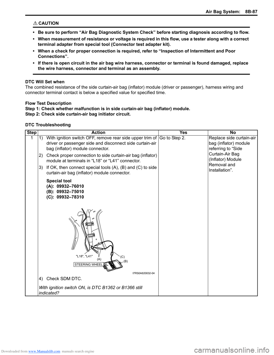
Step 1: Check whether malfunction is in side curtain-air bag (inflator) module.
Step 2: Check side curtain-air bag initiator circuit.
DTC Troubleshooting
Step Action YesNo
1 1) With ignition switch OFF, remove rear side upper trim of driver or passenger side and disconnect side curtain-air
bag (inflator) module connector.
2) Check proper connection to side curtain-air bag (inflator) module at terminals in “L18” or “L41” connector.
3) If OK, then connect special tools (A), (B) and (C) to side curtain-air bag (inflator) module connector.
Special tool
(A): 09932–76010
(B): 09932–75010
(C): 09932–78310
4) Check SDM DTC.
With ignition switch ON, is DTC B1362 or B1366 still
indicated? Go to Step 2.
Replace side curtain-air
bag (inflator) module
referring to “Side
Curtain-Air Bag
(Inflator) Module
Removal and
Installation”.
STEERING WHEEL(B)
(C)
(A)
"L18", "L41"
I7RS0A820032-04
Page 1127 of 1496
Downloaded from www.Manualslib.com manuals search engine Air Bag System: 8B-89
CAUTION!
• Be sure to perform “Air Bag Diagnostic System Check” before starting diagnosis according to flow.
• When measurement of resistance or voltage is required in this flow, use a tester along with a correct terminal adapter from special tool (Connector test adapter kit).
• When a check for proper connection is required, refer to “Inspection of Intermittent and Poor Connections”.
• If there is open circuit in the air bag wire harnes s, connector or terminal is found damaged, replace
the wire harness, connector and terminal as an assembly.
DTC Will Set when
The voltage measured at side curtain-air bag (driver or passenger) initiator circuit is below a specified value for
specified time.
Flow Test Description
Step 1: Check whether malfunction is in side curtain-air bag (inflator) module.
Step 2: Check side curtain-air bag initiator circuit.
DTC Troubleshooting
Step Action YesNo
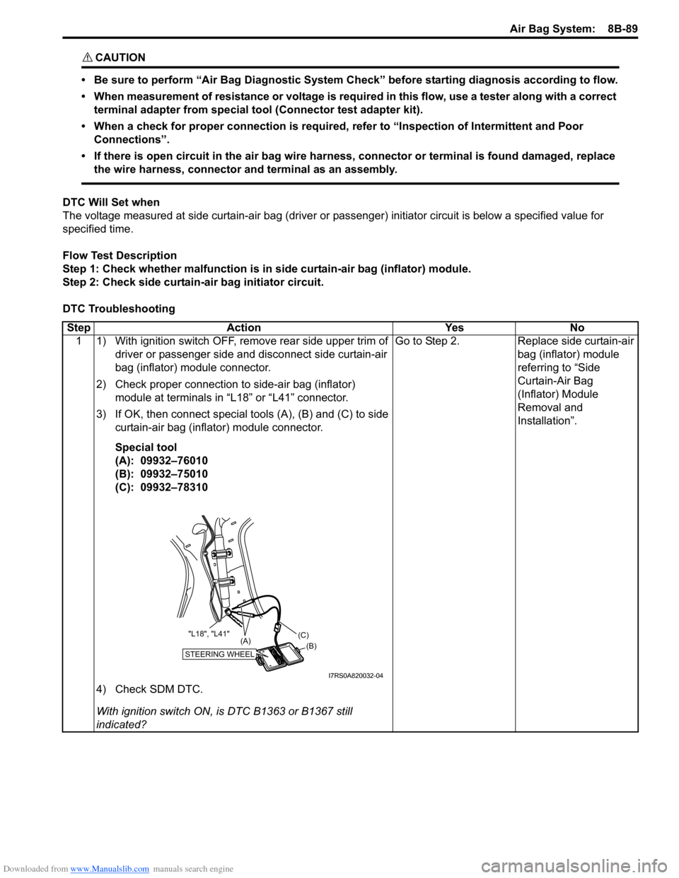
1 1) With ignition switch OFF, remove rear side upper trim of driver or passenger side and disconnect side curtain-air
bag (inflator) module connector.
2) Check proper connection to side-air bag (inflator) module at terminals in “L18” or “L41” connector.
3) If OK, then connect special tools (A), (B) and (C) to side curtain-air bag (inflator) module connector.
Special tool
(A): 09932–76010
(B): 09932–75010
(C): 09932–78310
4) Check SDM DTC.
With ignition switch ON, is DTC B1363 or B1367 still
indicated? Go to Step 2.
Replace side curtain-air
bag (inflator) module
referring to “Side
Curtain-Air Bag
(Inflator) Module
Removal and
Installation”.
STEERING WHEEL(B)
(C)
(A)
"L18", "L41"
I7RS0A820032-04
Page 1129 of 1496
Downloaded from www.Manualslib.com manuals search engine Air Bag System: 8B-91
CAUTION!
• Be sure to perform “Air Bag Diagnostic System Check” before starting diagnosis according to flow.
• When measurement of resistance or voltage is required in this flow, use a tester along with a correct terminal adapter from special tool (Connector test adapter kit).
• When a check for proper connection is required, refer to “Inspection of Intermittent and Poor Connections”.
• If there is open circuit in the air bag wire harnes s, connector or terminal is found damaged, replace
the wire harness, connector and terminal as an assembly.
DTC Will Set when
The voltage measured at side curtain-air bag (driver or passenger) initiator circuit is above a specified value for
specified time.
Flow Test Description
Step 1: Check whether malfunction is in side curtain-air bag (inflator) module.
Step 2: Check side curtain-air bag initiator circuit.
DTC Troubleshooting
Step Action YesNo
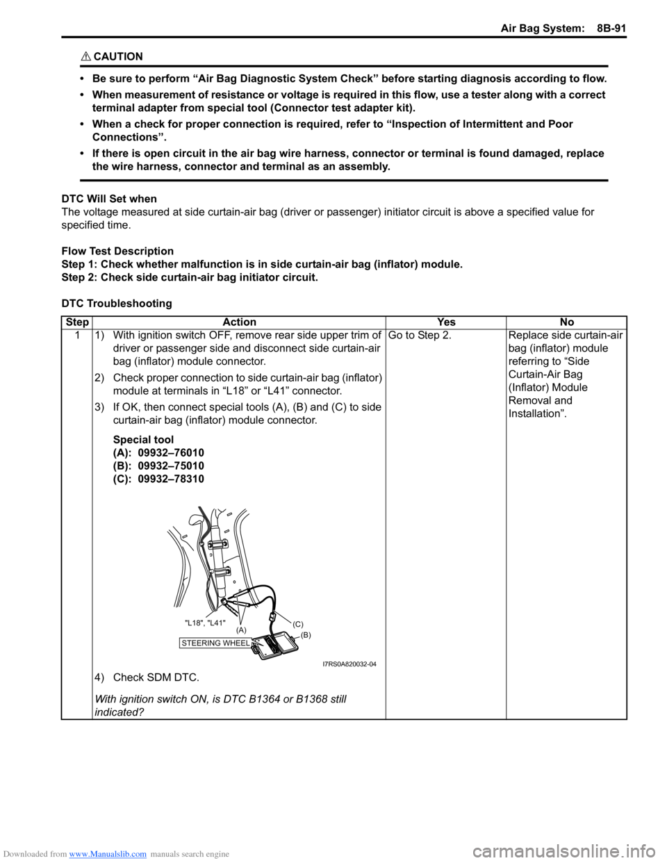
1 1) With ignition switch OFF, remove rear side upper trim of driver or passenger side and disconnect side curtain-air
bag (inflator) module connector.
2) Check proper connection to side curtain-air bag (inflator) module at terminals in “L18” or “L41” connector.
3) If OK, then connect special tools (A), (B) and (C) to side curtain-air bag (inflator) module connector.
Special tool
(A): 09932–76010
(B): 09932–75010
(C): 09932–78310
4) Check SDM DTC.
With ignition switch ON, is DTC B1364 or B1368 still
indicated? Go to Step 2.
Replace side curtain-air
bag (inflator) module
referring to “Side
Curtain-Air Bag
(Inflator) Module
Removal and
Installation”.
STEERING WHEEL(B)
(C)
(A)
"L18", "L41"
I7RS0A820032-04
Page 1138 of 1496
Downloaded from www.Manualslib.com manuals search engine 8B-100 Air Bag System:
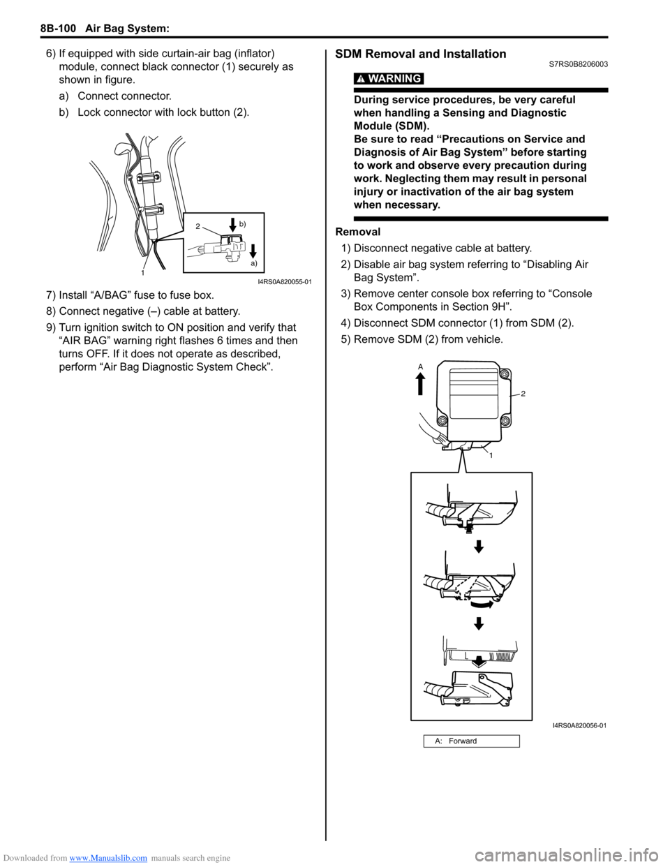
6) If equipped with side curtain-air bag (inflator) module, connect black connector (1) securely as
shown in figure.
a) Connect connector.
b) Lock connector with lock button (2).
7) Install “A/BAG” fuse to fuse box.
8) Connect negative (–) cable at battery.
9) Turn ignition switch to ON position and verify that “AIR BAG” warning right flashes 6 times and then
turns OFF. If it does not operate as described,
perform “Air Bag Diagn ostic System Check”.SDM Removal and InstallationS7RS0B8206003
WARNING!
During service procedures, be very careful
when handling a Sensing and Diagnostic
Module (SDM).
Be sure to read “Precautions on Service and
Diagnosis of Air Bag System” before starting
to work and observe every precaution during
work. Neglecting them ma y result in personal
injury or inactivation of the air bag system
when necessary.
Removal
1) Disconnect negative cable at battery.
2) Disable air bag system referring to “Disabling Air Bag System”.
3) Remove center console box referring to “Console Box Components in Section 9H”.
4) Disconnect SDM connector (1) from SDM (2).
5) Remove SDM (2) from vehicle.
1
2
a)
b)
I4RS0A820055-01
A: Forward
2
1
A
I4RS0A820056-01
Page 1139 of 1496
Downloaded from www.Manualslib.com manuals search engine Air Bag System: 8B-101
Installation1) Check that none of the following faulty conditions exists.
• Bend, scratch, deformity in vehicle body where SDM is mounted.
• Foreign matter or rust on mating surface of vehicle body where SDM is mounted.
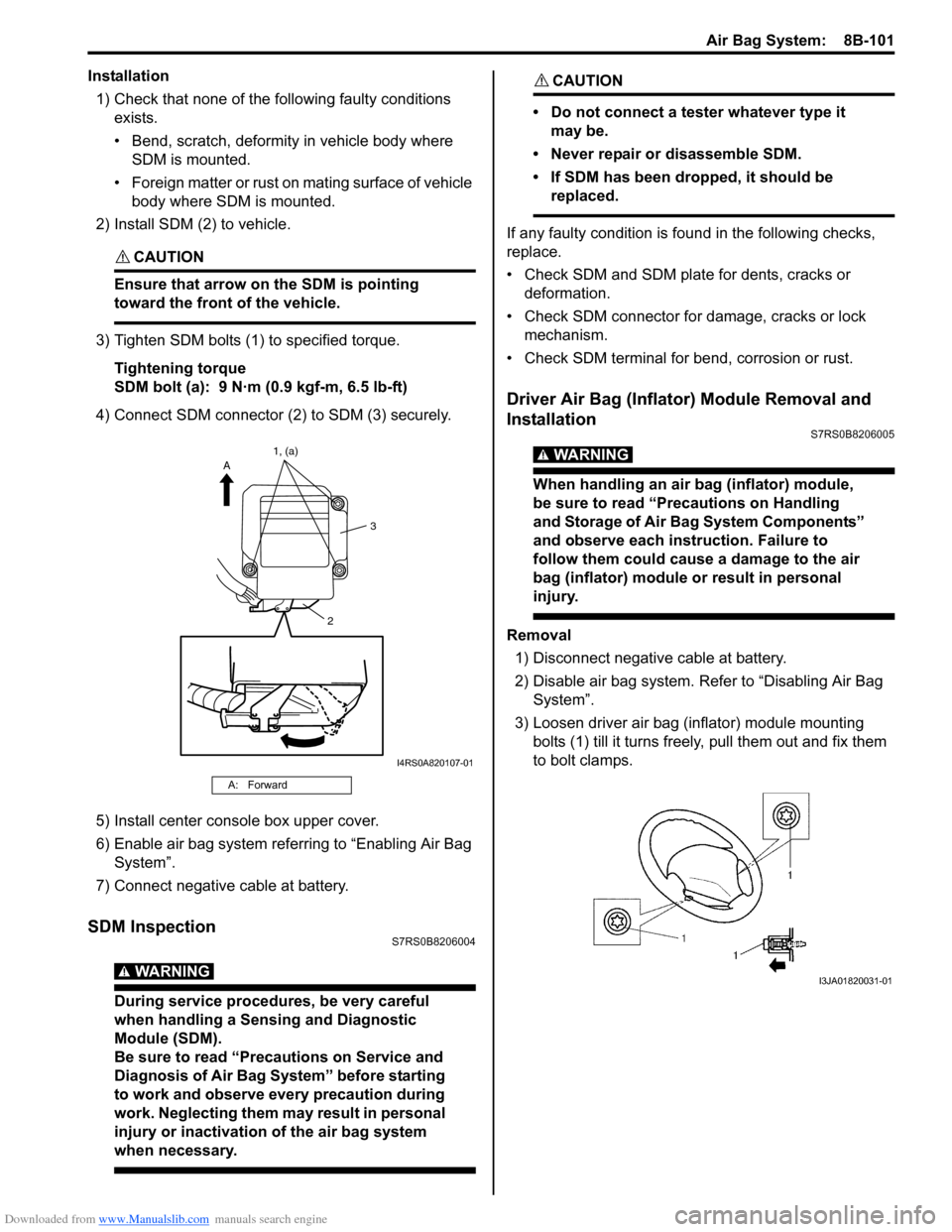
2) Install SDM (2) to vehicle.
CAUTION!
Ensure that arrow on the SDM is pointing
toward the front of the vehicle.
3) Tighten SDM bolts (1) to specified torque.
Tightening torque
SDM bolt (a): 9 N·m (0.9 kgf-m, 6.5 lb-ft)
4) Connect SDM connector (2) to SDM (3) securely.
5) Install center console box upper cover.
6) Enable air bag system referring to “Enabling Air Bag System”.
7) Connect negative cable at battery.
SDM InspectionS7RS0B8206004
WARNING!
During service procedures, be very careful
when handling a Sensing and Diagnostic
Module (SDM).
Be sure to read “Precautions on Service and
Diagnosis of Air Bag System” before starting
to work and observe every precaution during
work. Neglecting them ma y result in personal
injury or inactivation of the air bag system
when necessary.
CAUTION!
• Do not connect a tester whatever type it may be.
• Never repair or disassemble SDM.
• If SDM has been dropped, it should be replaced.
If any faulty condition is fo und in the following checks,
replace.
• Check SDM and SDM plate for dents, cracks or deformation.
• Check SDM connector for damage, cracks or lock mechanism.
• Check SDM terminal for bend, corrosion or rust.
Driver Air Bag (Inflator) Module Removal and
Installation
S7RS0B8206005
WARNING!
When handling an air bag (inflator) module,
be sure to read “Precautions on Handling
and Storage of Air Bag System Components”
and observe each instruction. Failure to
follow them could cause a damage to the air
bag (inflator) module or result in personal
injury.
Removal 1) Disconnect negative cable at battery.
2) Disable air bag system. Re fer to “Disabling Air Bag
System”.
3) Loosen driver air bag (inflator) module mounting bolts (1) till it turns freely, pull them out and fix them
to bolt clamps.
A: Forward
2 3
A
1, (a)
I4RS0A820107-01
I3JA01820031-01
Page 1141 of 1496
Downloaded from www.Manualslib.com manuals search engine Air Bag System: 8B-103
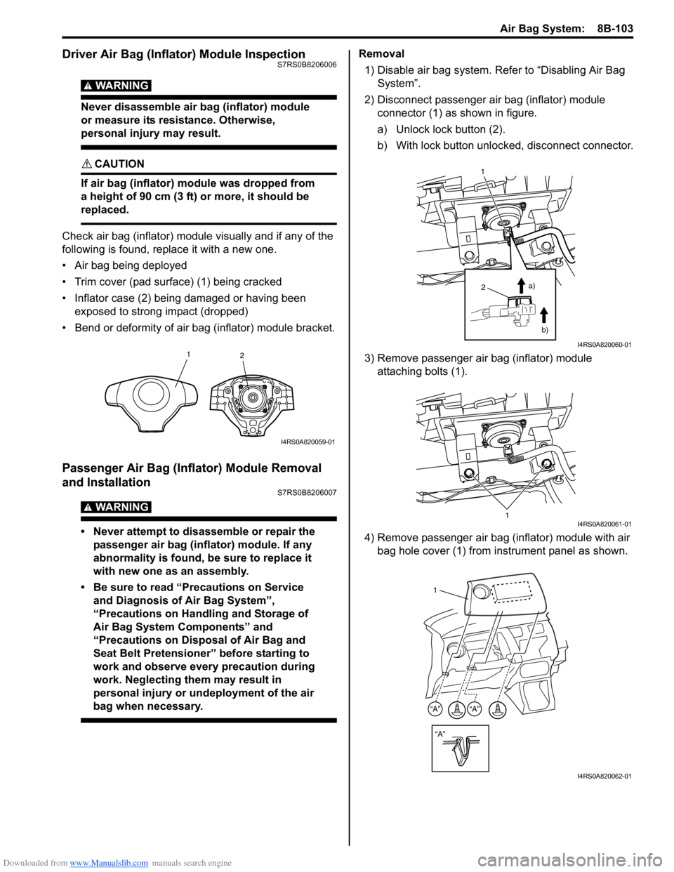
Driver Air Bag (Inflator) Module InspectionS7RS0B8206006
WARNING!
Never disassemble air bag (inflator) module
or measure its resistance. Otherwise,
personal injury may result.
CAUTION!
If air bag (inflator) module was dropped from
a height of 90 cm (3 ft) or more, it should be
replaced.
Check air bag (inflator) module visually and if any of the
following is found, replace it with a new one.
• Air bag being deployed
• Trim cover (pad surface) (1) being cracked
• Inflator case (2) being damaged or having been exposed to strong impact (dropped)
• Bend or deformity of air bag (inflator) module bracket.
Passenger Air Bag (Inflator) Module Removal
and Installation
S7RS0B8206007
WARNING!
• Never attempt to disassemble or repair the passenger air bag (inflator) module. If any
abnormality is found, be sure to replace it
with new one as an assembly.
• Be sure to read “Precautions on Service and Diagnosis of Air Bag System”,
“Precautions on Handling and Storage of
Air Bag System Components” and
“Precautions on Disposal of Air Bag and
Seat Belt Pretensioner” before starting to
work and observe every precaution during
work. Neglecting them may result in
personal injury or undeployment of the air
bag when necessary.
Removal
1) Disable air bag system. Re fer to “Disabling Air Bag
System”.
2) Disconnect passenger air bag (inflator) module connector (1) as shown in figure.
a) Unlock lock button (2).
b) With lock button unlocked, disconnect connector.
3) Remove passenger air bag (inflator) module attaching bolts (1).
4) Remove passenger air bag (inflator) module with air bag hole cover (1) from instrument panel as shown.
1 2
I4RS0A820059-01
2
1
a)b)
I4RS0A820060-01
1I4RS0A820061-01
“A”
“A”“A”
1
I4RS0A820062-01