1g 1 SUZUKI SWIFT 2007 2.G Service Workshop Manual
[x] Cancel search | Manufacturer: SUZUKI, Model Year: 2007, Model line: SWIFT, Model: SUZUKI SWIFT 2007 2.GPages: 1496, PDF Size: 34.44 MB
Page 931 of 1496
Downloaded from www.Manualslib.com manuals search engine Power Assisted Steering System: 6C-49
Special Tools and Equipment
Recommended Service MaterialS7RS0B6308001
NOTE
Required service material is also described in the following.
“Steering Gear Case Assembly Components”
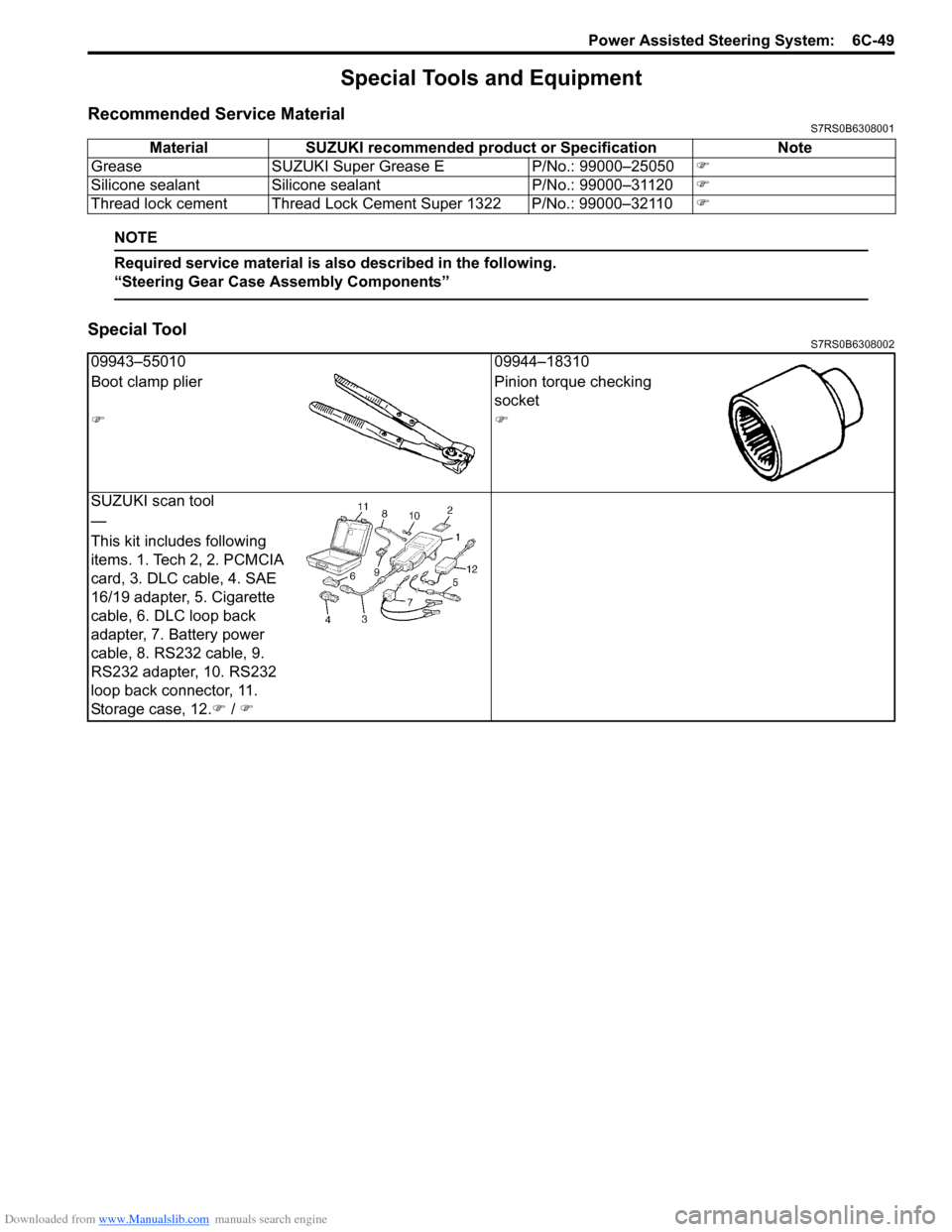
Special ToolS7RS0B6308002
Material SUZUKI recommended product or Specification Note
Grease SUZUKI Super Grease E P/No.: 99000–25050�)
Silicone sealant Silicone sealant P/No.: 99000–31120�)
Thread lock cement Thread Lock Cement Super 1322 P/No.: 99000–32110 �)
09943–5501009944–18310
Boot clamp plier Pinion torque checking
socket
�)�)
SUZUKI scan tool
—
This kit includes following
items. 1. Tech 2, 2. PCMCIA
card, 3. DLC cable, 4. SAE
16/19 adapter, 5. Cigarette
cable, 6. DLC loop back
adapter, 7. Battery power
cable, 8. RS232 cable, 9.
RS232 adapter, 10. RS232
loop back connector, 11.
Storage case, 12. �) / �)
Page 932 of 1496

Downloaded from www.Manualslib.com manuals search engine 6C-50 Power Assisted Steering System:
Page 933 of 1496

Downloaded from www.Manualslib.com manuals search engine Table of Contents 7- i
7
Section 7
CONTENTS
HVAC
Precautions ................................................. 7-1
Precautions............................................................. 7-1
Precautions on HVAC ........................................... 7-1
Heater and Ventilation.... ......................... 7A-1
General Description ............................................. 7A-1
Heater and Ventilation Construction ................... 7A-1
Schematic and Routing Diagram ........................ 7A-2 Heater and Ventilation Wiring Circuit Diagram .... 7A-2
Diagnostic Information and Procedures ............ 7A-3 Heater and Ventilation Symptom Diagnosis........ 7A-3
Repair Instructions .............................................. 7A-4 HVAC Unit Components ..................................... 7A-4
HVAC Unit Removal and Installation .................. 7A-4
Blower Motor Removal and Installation............... 7A-4
Blower Motor Inspection ..................................... 7A-4
Blower Motor Resistor Removal and Installation ......................................................... 7A-5
Blower Motor Resistor Inspection ....................... 7A-5
Blower Motor Relay Inspection ........................... 7A-6
HVAC Control Unit Components ......................... 7A-6
HVAC Control Unit Remova l and Installation ...... 7A-7
Blower Speed Selector In spection ...................... 7A-9
Air Intake Selector Inspec tion ............................. 7A-9
Air Intake Control Actuator Removal and Installation ......................................................... 7A-9
Air Intake Control Actuator Inspection .............. 7A-10
Center Ventilation Louver Removal and Installation ....................................................... 7A-10
Side Ventilation Louver Removal and Installation ....................................................... 7A-11
HVAC Air Filter Removal and Installation (If Equipped)........................................................ 7A-12
HVAC Air Filter Inspection (If Equipped) ........... 7A-12
Air Conditioning System... ...................... 7B-1
Manual Type ............................................................ 7B-1
Precautions........................................................... 7B-1A/C System Caution ............................................ 7B-1
Precautions on Servicing A/C System ................ 7B-1
General Description ............................................. 7B-3 Refrigerant Type Identifica tion ............................ 7B-3
Sub-Cool A/C System Description ...................... 7B-4
A/C Operation Description .................................. 7B-4 Schematic and Routing Diagram ........................7B-5
Major Components of A/C System ...................... 7B-5
A/C System Wiring Diagram ............................... 7B-6
Diagnostic Information and Procedures ............7B-7 A/C System Symptom Diagnosis ........................ 7B-7
Abnormal Noise Sympto m Diagnosis of A/C
System .............................................................. 7B-9
A/C System Performance Inspection ................ 7B-10
A/C System Inspection at ECM ......................... 7B-15
Repair Instructions ........... .................................7B-16
Operation Procedure for Re frigerant Charge .... 7B-16
Condenser Assembly On-Vehicle Inspection .... 7B-21
Condenser Assembly Removal and Installation ....................................................... 7B-21
Receiver/Dryer Removal and Installation .......... 7B-22
HVAC Unit Components ................................... 7B-23
HVAC Unit Removal and In stallation ................ 7B-24
Evaporator Inspection ....................................... 7B-24
Evaporator Thermistor (Evaporator Temperature Sensor) Removal and
Installation ....................................................... 7B-25
Evaporator Thermistor (Evaporator Temperature Sensor) Inspec tion..................... 7B-25
Expansion Valve Removal and Installation ....... 7B-26
Expansion Valve Inspection .............................. 7B-26
A/C Refrigerant Pressure Sensor and Its Circuit Inspection............................................. 7B-26
A/C Refrigerant Pressu re Sensor Removal
and Installation ................................................ 7B-26
A/C Switch Inspection ....................................... 7B-27
Compressor Relay Inspection ........................... 7B-27
Compressor Drive Belt Inspection and Adjustment ...................................................... 7B-27
Compressor Drive Belt Removal and Installation ....................................................... 7B-28
Compressor Assembly Removal and Installation ....................................................... 7B-28
Compressor Assembly Components................. 7B-29
Magnet Clutch Inspection.................................. 7B-29
Magnet Clutch Removal and Installation........... 7B-29
Relief Valve Inspection...................................... 7B-31
Relief Valve Removal and Installation............... 7B-32
Specifications .................... .................................7B-32
Tightening Torque Specifications ...................... 7B-32
Special Tools and Equipmen t ...........................7B-33
Page 934 of 1496

Downloaded from www.Manualslib.com manuals search engine 7-ii Table of Contents
Recommended Service Material ....................... 7B-33
Special Tool ...................................................... 7B-33
Automatic Type .................... .................................7B-34
Precautions.........................................................7B-34 A/C System Caution .......................................... 7B-34
Precautions in Diagnosing Trouble ................... 7B-34
Precautions on Servicing A/C System .............. 7B-34
General Description .......... .................................7B-34
Auto A/C System Descript ion ............................ 7B-34
HVAC Control Module Operation Description ... 7B-36
Refrigerant Type Identifica tion .......................... 7B-36
Sub-Cool A/C System Description .................... 7B-36
A/C Operation Description ................................ 7B-36
On-Board Diagnostic System Description ......... 7B-37
Schematic and Routing Diagram ......................7B-37 Major Components of A/C System .................... 7B-37
A/C System Wiring Diagra m ............................. 7B-38
Diagnostic Information and Procedures ..........7B-39 A/C System Symptom Diagnosis ...................... 7B-39
Abnormal Noise Sympto m Diagnosis of A/C
System ............................................................ 7B-42
DTC Check........................................................ 7B-42
DTC Clearance ................................................. 7B-43
DTC Table ......................................................... 7B-44
Fail-Safe Table ................. ................................. 7B-45
Scan Tool Data ................................................. 7B-46
Air Conditioning System Check......................... 7B-47
Visual Inspection ............................................... 7B-49
DTC B1502: Inside Air Temperature Sensor and/or Its Circuit Malfunction .......................... 7B-49
DTC B1503: A/C Evaporator Air Temperature Sensor and/or Its Circuit Malfunction .............. 7B-50
DTC B1504: Sunload Sensor and/or Its Circuit Malfunction ......... ................................. 7B-52
DTC B1511: Temperature Control Actuator (Position Sensor) and/or Its Circuit
Malfunction ...................................................... 7B-53
DTC B1512: Air flow Control Actuator (Position Sensor) and/or Its Circuit
Malfunction ...................................................... 7B-55
DTC B1513: Temperature Control Actuator and/or Its Circuit Malfunction .......................... 7B-57
DTC B1514: Air Flow Co ntrol Actuator and/or
Its Circuit Malfunction ...................................... 7B-60
DTC B1541: HVAC Control Module Back-Up Power Supply Malfunction .............................. 7B-62
DTC B1546: A/C Refrigerant Pressure Malfunction ...................................................... 7B-63
DTC B1551: Serial Communication Circuit Malfunction ...................................................... 7B-63
DTC B1552: Serial Communication Signal Malfunction ...................................................... 7B-64
DTC B1553: CAN Communication Signal Malfunction ...................................................... 7B-65
DTC B1557: Vehicle Speed Sensor Signal Malfunction ...................................................... 7B-65
DTC B1561: Engine Coolant Temperature Sensor Signal Malfunctio n .............................. 7B-66 DTC B1562: Outside Air Temperature Sensor
Signal Malfunction ........................................... 7B-66
DTC B1563: A/C Refr igerant Pressure
Sensor Signal Malfunction .............................. 7B-66
Inspection of HVAC Control Module and Its Circuit .............................................................. 7B-67
A/C System Performance Inspection ................ 7B-70
A/C System Inspection at ECM ......................... 7B-70
Repair Instructions ............ ................................7B-71
Operation Procedure for Refrigerant Charge .... 7B-71
HVAC Unit Components ................................... 7B-72
HVAC Unit Removal and In stallation ................ 7B-73
Temperature Control Actuator Removal and Installation ....................................................... 7B-73
Temperature Control Actuat or Inspection ......... 7B-73
Air Flow Control Actuator Removal and Installation ....................................................... 7B-74
Air Flow Control Actuator Inspection ................. 7B-74
Air Intake Control Actuator Removal and Installation ....................................................... 7B-75
Air Intake Control Actuator Inspection............... 7B-75
Actuator Linkage Inspection .............................. 7B-76
Blower Motor Controller Removal and Installation ....................................................... 7B-76
Blower Motor Controller Inspection ................... 7B-76
HVAC Control Module Removal and Installation ....................................................... 7B-77
Sunload Sensor Removal and Installation ........ 7B-77
Sunload Sensor Inspection ............................... 7B-77
Outside Air Temperature Sensor Removal and Installation ................................................ 7B-77
Outside Air Temperature Sensor Inspection ..... 7B-77
Inside Air Temperature Sensor Removal and Installation ....................................................... 7B-78
Inside Air Temperature Sens or Inspection ........ 7B-78
Condenser Assembly On-Vehicle Inspection .... 7B-78
Condenser Assembly Removal and Installation ....................................................... 7B-78
Receiver/Dryer Removal and Installation .......... 7B-78
Evaporator Inspection ....................................... 7B-78
Evaporator Temperature Sensor Removal and Installation ................................................ 7B-78
Evaporator Temperature Se nsor Inspection ..... 7B-78
Expansion Valve Removal an d Installation ....... 7B-78
Expansion Valve Inspection .............................. 7B-78
A/C Refrigerant Pressure Sensor and Its Circuit Inspection............................................. 7B-78
A/C Refrigerant Pressu re Sensor Removal
and Installation ................................................ 7B-78
Compressor Relay Inspection .
.......................... 7B-78
Compressor Drive Belt Inspection and Adjustment ...................................................... 7B-78
Compressor Drive Belt Removal and Installation ....................................................... 7B-79
Compressor Assembly Removal and Installation ....................................................... 7B-79
Compressor Assembly Components................. 7B-79
Magnet Clutch Removal and Installation........... 7B-79
Magnet Clutch Inspection.................................. 7B-79
Relief Valve Inspection...................................... 7B-79
Page 935 of 1496
Downloaded from www.Manualslib.com manuals search engine Table of Contents 7-iii
Special Tools and Equipment ........................... 7B-79 Special Tool ...................................................... 7B-79
Page 936 of 1496
Downloaded from www.Manualslib.com manuals search engine 7-1 Precautions:
HVAC
Precautions
Precautions
Precautions on HVACS7RS0B7000001
Air Bag Warning
Refer to “Air Bag Warning in Section 00”.
A/C System Caution
Refer to “A/C System Caution in Section 7B”.
Precautions on Servicing A/C System
Refer to “Precautions on Servicing A/C System in Section 7B”.
Page 937 of 1496
Downloaded from www.Manualslib.com manuals search engine Heater and Ventilation: 7A-1
HVAC
Heater and Ventilation
General Description
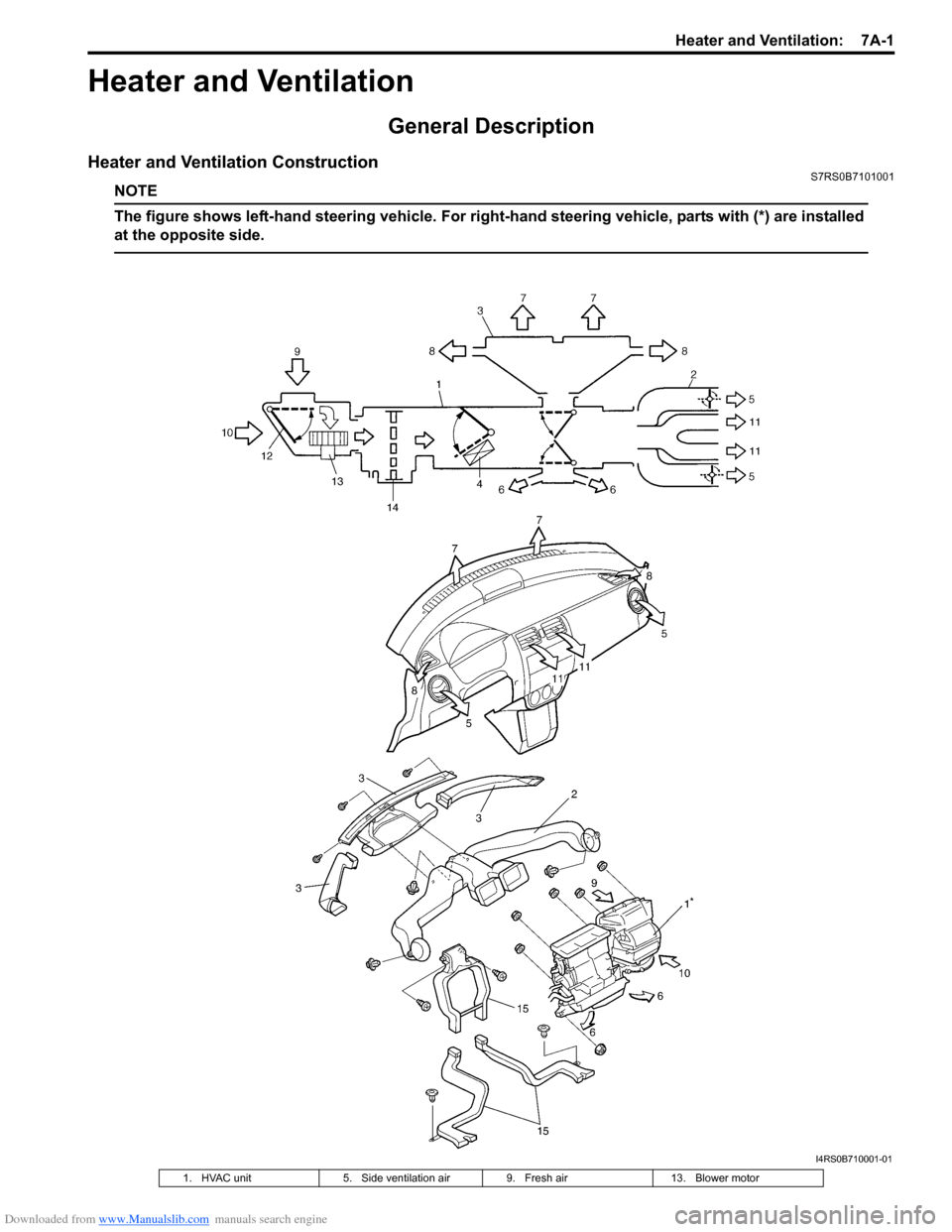
Heater and Ventilation ConstructionS7RS0B7101001
NOTE
The figure shows left-hand steering vehicle. For right-hand steering vehicle, parts with (*) are installed
at the opposite side.
I4RS0B710001-01
1. HVAC unit 5. Side ventilation air 9. Fresh air 13. Blower motor
Page 938 of 1496
Downloaded from www.Manualslib.com manuals search engine 7A-2 Heater and Ventilation:
Schematic and Routing Diagram
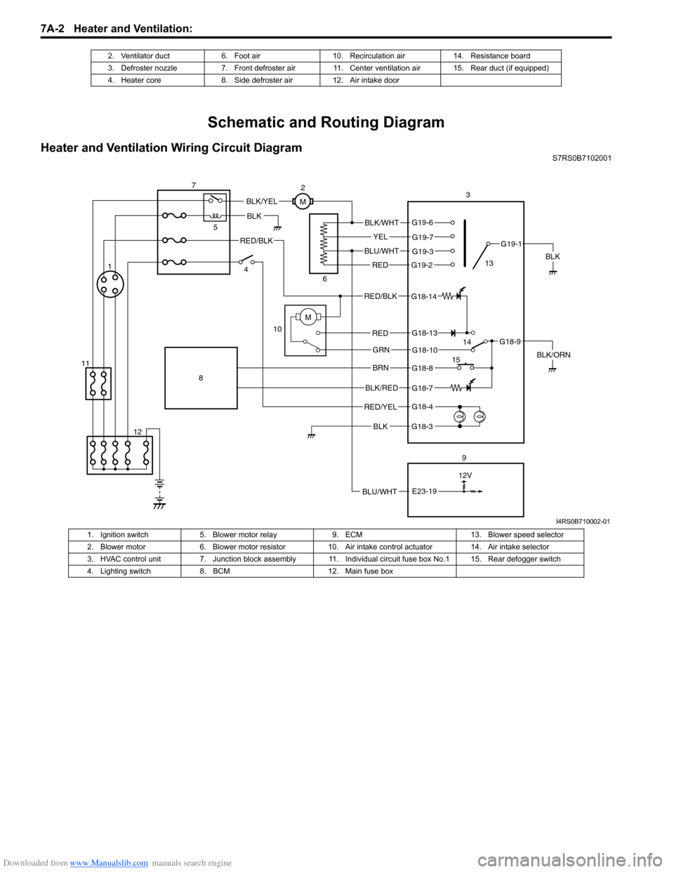
Heater and Ventilation Wiring Circuit DiagramS7RS0B7102001
2. Ventilator duct 6. Foot air 10. Recirculation air 14. Resistance board
3. Defroster nozzle 7. Front defroster air 11. Center ventilation air 15. Rear duct (if equipped)
4. Heater core 8. Side defroster air 12. Air intake door
BLK
RED/BLK
3
5
7
BLK
2
M
12V
BLU/WHTE23-19
G18-3
G18-4
G18-7
G18-8
G18-10
G18-13
G19-2
G19-3
G19-7
G19-6
G19-1
G18-9
G18-14
BLK/WHT
YEL
BLU/WHT
RED
RED/BLK
RED
GRN
BRN
BLK/RED
RED/YEL
BLK
BLK/YEL
BLK/ORN
4
6
10
8
9
M1
12
11 13
14
15
I4RS0B710002-01
1. Ignition switch 5. Blower motor relay 9. ECM 13. Blower speed selector
2. Blower motor 6. Blower motor resistor 10. Air intake control actuator 14. Air intake selector
3. HVAC control unit 7. Junction block assembly 11. Ind ividual circuit fuse box No.1 15. Rear defogger switch
4. Lighting switch 8. BCM 12. Main fuse box
Page 939 of 1496
Downloaded from www.Manualslib.com manuals search engine Heater and Ventilation: 7A-3
Diagnostic Information and Procedures
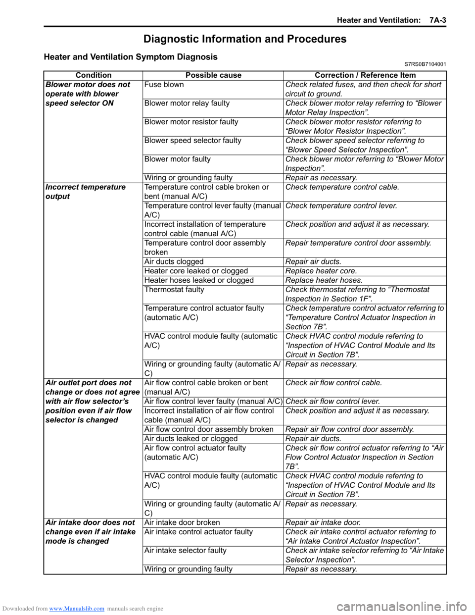
Heater and Ventilation Symptom DiagnosisS7RS0B7104001
ConditionPossible cause Correction / Reference Item
Blower motor does not
operate with blower
speed selector ON Fuse blown
Check related fuses, and then check for short
circuit to ground.
Blower motor relay faulty Check blower motor relay referring to “Blower
Motor Relay Inspection”.
Blower motor resistor faulty Check blower motor resistor referring to
“Blower Motor Resistor Inspection”.
Blower speed selector faulty Check blower speed selector referring to
“Blower Speed Selector Inspection”.
Blower motor faulty Check blower motor referring to “Blower Motor
Inspection”.
Wiring or grounding faulty Repair as necessary.
Incorrect temperature
output Temperature control cable broken or
bent (manual A/C) Check temperature control cable.
Temperature control lever faulty (manual
A/C) Check temperature control lever.
Incorrect installation of temperature
control cable (manual A/C) Check position and adjust it as necessary.
Temperature control door assembly
broken Repair temperature control door assembly.
Air ducts clogged Repair air ducts.
Heater core leaked or clogged Replace heater core.
Heater hoses leaked or clogged Replace heater hoses.
Thermostat faulty Check thermostat referring to “Thermostat
Inspection in Section 1F”.
Temperature control actuator faulty
(automatic A/C) Check temperature control actuator referring to
“Temperature Control Actuator Inspection in
Section 7B”.
HVAC control module faulty (automatic
A/C) Check HVAC control module referring to
“Inspection of HVAC Control Module and Its
Circuit in Section 7B”.
Wiring or grounding faulty (automatic A/
C) Repair as necessary.
Air outlet port does not
change or does not agree
with air flow selector’s
position even if air flow
selector is changed Air flow control cable broken or bent
(manual A/C)
Check air flow control cable.
Air flow control lever faulty (manual A/C) Check air flow control lever.
Incorrect installation of air flow control
cable (manual A/C) Check position and adjust it as necessary.
Air flow control door assembly broken Repair air flow control door assembly.
Air ducts leaked or clogged Repair air ducts.
Air flow control actuator faulty
(automatic A/C) Check air flow control actuator referring to “Air
Flow Control Actuator
Inspection in Section
7B”.
HVAC control module faulty (automatic
A/C) Check HVAC control module referring to
“Inspection of HVAC Control Module and Its
Circuit in Section 7B”.
Wiring or grounding faulty (automatic A/
C) Repair as necessary.
Air intake door does not
change even if air intake
mode is changed Air intake door broken
Repair air intake door.
Air intake control actuator faulty Check air intake control actuator referring to
“Air Intake Control Actuator Inspection”.
Air intake selector faulty Check air intake selector referring to “Air Intake
Selector Inspection”.
Wiring or grounding faulty Repair as necessary.
Page 940 of 1496
Downloaded from www.Manualslib.com manuals search engine 7A-4 Heater and Ventilation:
Repair Instructions
HVAC Unit ComponentsS7RS0B7106001
For manual type A/C, refer to “HVAC Unit Components
in Section 7B”.
For automatic type A/C, refer to “HVAC Unit
Components in Section 7B”.
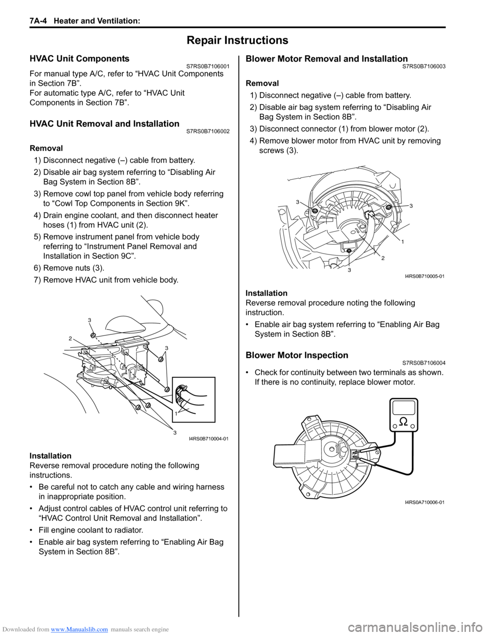
HVAC Unit Removal and InstallationS7RS0B7106002
Removal
1) Disconnect negative (–) cable from battery.
2) Disable air bag system referring to “Disabling Air Bag System in Section 8B”.
3) Remove cowl top panel from vehicle body referring to “Cowl Top Components in Section 9K”.
4) Drain engine coolant, and then disconnect heater hoses (1) from HVAC unit (2).
5) Remove instrument panel from vehicle body referring to “Instrument Panel Removal and
Installation in Section 9C”.
6) Remove nuts (3).
7) Remove HVAC unit from vehicle body.
Installation
Reverse removal procedure noting the following
instructions.
• Be careful not to catch any cable and wiring harness in inappropriate position.
• Adjust control cables of HVAC control unit referring to “HVAC Control Unit Remo val and Installation”.
• Fill engine coolant to radiator.
• Enable air bag system referring to “Enabling Air Bag System in Section 8B”.
Blower Motor Removal and InstallationS7RS0B7106003
Removal
1) Disconnect negative (–) cable from battery.
2) Disable air bag system referring to “Disabling Air Bag System in Section 8B”.
3) Disconnect connector (1) from blower motor (2).
4) Remove blower motor from HVAC unit by removing screws (3).
Installation
Reverse removal procedure noting the following
instruction.
• Enable air bag system referring to “Enabling Air Bag System in Section 8B”.
Blower Motor InspectionS7RS0B7106004
• Check for continuity between two terminals as shown. If there is no continuity, replace blower motor.
3
2
3
1
3I4RS0B710004-01
3
1
2
3
3
I4RS0B710005-01
I4RS0A710006-01