Blower motor controller SUZUKI SWIFT 2007 2.G Service Workshop Manual
[x] Cancel search | Manufacturer: SUZUKI, Model Year: 2007, Model line: SWIFT, Model: SUZUKI SWIFT 2007 2.GPages: 1496, PDF Size: 34.44 MB
Page 65 of 1496
![SUZUKI SWIFT 2007 2.G Service Workshop Manual Downloaded from www.Manualslib.com manuals search engine Engine General Information and Diagnosis: 1A-15
Terminal Arrangement of ECM Coupler (Viewed from Harness Side)
[A]: Manual A/C model24. ABS / SUZUKI SWIFT 2007 2.G Service Workshop Manual Downloaded from www.Manualslib.com manuals search engine Engine General Information and Diagnosis: 1A-15
Terminal Arrangement of ECM Coupler (Viewed from Harness Side)
[A]: Manual A/C model24. ABS /](/img/20/7607/w960_7607-64.png)
Downloaded from www.Manualslib.com manuals search engine Engine General Information and Diagnosis: 1A-15
Terminal Arrangement of ECM Coupler (Viewed from Harness Side)
[A]: Manual A/C model24. ABS / ESP® control module 49. Radiator cooling fan motor
[B]: Auto A/C model 25. TCM 50. “RDTR FAN” fuse
1. ECM 26. To other control module connected CAN 51. A/C compressor relay
2. APP sensor assembly 27. Generator 52. Magnet clutch of compressor (A/C model)
3. Shield wire 28. Electric load current sensor (if equipped) 53. “A/C CPRSR” fuse
4. CMP sensor 29. Brake light 54. Ignition coil assembly (for No.1 and No.4 spark
plugs)
5. CKP sensor 30. Brake light switch 55. Ignition coil assembly (for No.2 and No.3 spark
plugs)
6. MAF and IAT sensor 31. Diagnosis connector (Hong Kong model) 56. P/S control module
7. MAP sensor 32. Throttle actuator control relay 57. “RADIO” fuse
8. ECT sensor 33. “THR MOT” fuse 58. Main relay
9. A/C refrigerant pressure sensor 34. Throttle throttle body assembly 59. “IG COIL” fuse
10. A/C evaporator outlet air temp. sensor (Manual A/C model) 35. Throttle actuator
60. Ignition switch
11. HO2S-1 36. TP sensor 61. “IG ACC” fuse
12. HO2S-2 37. Injector No.1 62. “FI” fuse
13. Knock sensor 38. Injector No.2 63. Starting motor control relay
14. Blower motor relay 39. Injector No.3 64. “ST SIG” fuse
15. Blower motor 40. Injector No.4 65. “ST MOT” fuse
16. Blower motor resistor 41. EVAP canister purge valve66. Transmission range switch (A/T model) or CPP
switch (Hong Kong model with M/T)
17. Blower speed selector 42. EGR valve 67. Starting motor
18. A/C switch 43. Oil control valve (Camshaft position
control) (VVT model) 68. Immobilizer coil antenna
19. Blower motor controller 44. Fuel pump relay 69. Main fuse box
20. HVAC control module 45. Fuel pump 70. Battery
21. Data link connector (DLC) 46. Radiator cooling fan motor relay No.1 71. Barometric pressure sensor
22. To other control module connected with DLC 47. Radiator cooling fan motor relay No.2
72. Engine ground
23. BCM 48. Radiator cooling fan motor relay No.3 73. Body ground
E23 C37
34
1819
567
1011
17
20
47 46
495051
2122
52 16
25 9
24
14
29
55
57 54 53
59
60 58 2
262728
15
30
56 4832 31
34353637
40
42 39 38
44
45 43 41 331
1213
238
34
1819
567
1011
17
20
47 46
495051
2122
52 16
25 9
24
14
29
55
57 54 53
59
60 58 2
262728
15
30
56 4832 31
34353637
40
42 39 38
44
45 43 41 331
1213
238
I4RS0A110008-01
Page 934 of 1496

Downloaded from www.Manualslib.com manuals search engine 7-ii Table of Contents
Recommended Service Material ....................... 7B-33
Special Tool ...................................................... 7B-33
Automatic Type .................... .................................7B-34
Precautions.........................................................7B-34 A/C System Caution .......................................... 7B-34
Precautions in Diagnosing Trouble ................... 7B-34
Precautions on Servicing A/C System .............. 7B-34
General Description .......... .................................7B-34
Auto A/C System Descript ion ............................ 7B-34
HVAC Control Module Operation Description ... 7B-36
Refrigerant Type Identifica tion .......................... 7B-36
Sub-Cool A/C System Description .................... 7B-36
A/C Operation Description ................................ 7B-36
On-Board Diagnostic System Description ......... 7B-37
Schematic and Routing Diagram ......................7B-37 Major Components of A/C System .................... 7B-37
A/C System Wiring Diagra m ............................. 7B-38
Diagnostic Information and Procedures ..........7B-39 A/C System Symptom Diagnosis ...................... 7B-39
Abnormal Noise Sympto m Diagnosis of A/C
System ............................................................ 7B-42
DTC Check........................................................ 7B-42
DTC Clearance ................................................. 7B-43
DTC Table ......................................................... 7B-44
Fail-Safe Table ................. ................................. 7B-45
Scan Tool Data ................................................. 7B-46
Air Conditioning System Check......................... 7B-47
Visual Inspection ............................................... 7B-49
DTC B1502: Inside Air Temperature Sensor and/or Its Circuit Malfunction .......................... 7B-49
DTC B1503: A/C Evaporator Air Temperature Sensor and/or Its Circuit Malfunction .............. 7B-50
DTC B1504: Sunload Sensor and/or Its Circuit Malfunction ......... ................................. 7B-52
DTC B1511: Temperature Control Actuator (Position Sensor) and/or Its Circuit
Malfunction ...................................................... 7B-53
DTC B1512: Air flow Control Actuator (Position Sensor) and/or Its Circuit
Malfunction ...................................................... 7B-55
DTC B1513: Temperature Control Actuator and/or Its Circuit Malfunction .......................... 7B-57
DTC B1514: Air Flow Co ntrol Actuator and/or
Its Circuit Malfunction ...................................... 7B-60
DTC B1541: HVAC Control Module Back-Up Power Supply Malfunction .............................. 7B-62
DTC B1546: A/C Refrigerant Pressure Malfunction ...................................................... 7B-63
DTC B1551: Serial Communication Circuit Malfunction ...................................................... 7B-63
DTC B1552: Serial Communication Signal Malfunction ...................................................... 7B-64
DTC B1553: CAN Communication Signal Malfunction ...................................................... 7B-65
DTC B1557: Vehicle Speed Sensor Signal Malfunction ...................................................... 7B-65
DTC B1561: Engine Coolant Temperature Sensor Signal Malfunctio n .............................. 7B-66 DTC B1562: Outside Air Temperature Sensor
Signal Malfunction ........................................... 7B-66
DTC B1563: A/C Refr igerant Pressure
Sensor Signal Malfunction .............................. 7B-66
Inspection of HVAC Control Module and Its Circuit .............................................................. 7B-67
A/C System Performance Inspection ................ 7B-70
A/C System Inspection at ECM ......................... 7B-70
Repair Instructions ............ ................................7B-71
Operation Procedure for Refrigerant Charge .... 7B-71
HVAC Unit Components ................................... 7B-72
HVAC Unit Removal and In stallation ................ 7B-73
Temperature Control Actuator Removal and Installation ....................................................... 7B-73
Temperature Control Actuat or Inspection ......... 7B-73
Air Flow Control Actuator Removal and Installation ....................................................... 7B-74
Air Flow Control Actuator Inspection ................. 7B-74
Air Intake Control Actuator Removal and Installation ....................................................... 7B-75
Air Intake Control Actuator Inspection............... 7B-75
Actuator Linkage Inspection .............................. 7B-76
Blower Motor Controller Removal and Installation ....................................................... 7B-76
Blower Motor Controller Inspection ................... 7B-76
HVAC Control Module Removal and Installation ....................................................... 7B-77
Sunload Sensor Removal and Installation ........ 7B-77
Sunload Sensor Inspection ............................... 7B-77
Outside Air Temperature Sensor Removal and Installation ................................................ 7B-77
Outside Air Temperature Sensor Inspection ..... 7B-77
Inside Air Temperature Sensor Removal and Installation ....................................................... 7B-78
Inside Air Temperature Sens or Inspection ........ 7B-78
Condenser Assembly On-Vehicle Inspection .... 7B-78
Condenser Assembly Removal and Installation ....................................................... 7B-78
Receiver/Dryer Removal and Installation .......... 7B-78
Evaporator Inspection ....................................... 7B-78
Evaporator Temperature Sensor Removal and Installation ................................................ 7B-78
Evaporator Temperature Se nsor Inspection ..... 7B-78
Expansion Valve Removal an d Installation ....... 7B-78
Expansion Valve Inspection .............................. 7B-78
A/C Refrigerant Pressure Sensor and Its Circuit Inspection............................................. 7B-78
A/C Refrigerant Pressu re Sensor Removal
and Installation ................................................ 7B-78
Compressor Relay Inspection .
.......................... 7B-78
Compressor Drive Belt Inspection and Adjustment ...................................................... 7B-78
Compressor Drive Belt Removal and Installation ....................................................... 7B-79
Compressor Assembly Removal and Installation ....................................................... 7B-79
Compressor Assembly Components................. 7B-79
Magnet Clutch Removal and Installation........... 7B-79
Magnet Clutch Inspection.................................. 7B-79
Relief Valve Inspection...................................... 7B-79
Page 983 of 1496
Downloaded from www.Manualslib.com manuals search engine Air Conditioning System: Automatic Type 7B-35
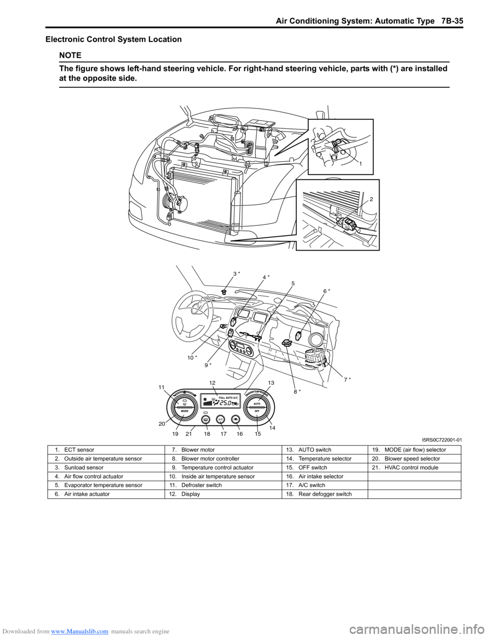
Electronic Control System Location
NOTE
The figure shows left-hand steering vehicle. For right-hand steering vehicle, parts with (*) are installed
at the opposite side.
1
2
3 * 4 *
5
6 *
7 *
8 *
9 *
10 *
21
11
12 13
14
15161718
19
20
I5RS0C722001-01
1. ECT sensor
7. Blower motor13. AUTO switch19. MODE (air flow) selector
2. Outside air temperature sensor 8. Blower motor controller 14. Temperature selector 20. Blower speed selector
3. Sunload sensor 9. Temperature control actuator15. OFF switch21. HVAC control module
4. Air flow control actuator 10. Inside air temperature sensor 16. Air intake selector
5. Evaporator temperature sensor 11. Defroster switch 17. A/C switch
6. Air intake actuator 12. Display 18. Rear defogger switch
Page 984 of 1496
Downloaded from www.Manualslib.com manuals search engine 7B-36 Air Conditioning System: Automatic Type
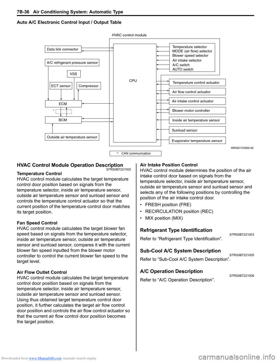
Auto A/C Electronic Control Input / Output Table
HVAC Control Module Operation DescriptionS7RS0B7221002
Temperature Control
HVAC control module calculates the target temperature
control door position based on signals from the
temperature selector, inside air temperature sensor,
outside air temperature sensor and sunload sensor and
controls the temperature control actuator so that the
current position of the temperature control door matches
its target position.
Fan Speed Control
HVAC control module calculates the target blower fan
speed based on signals from the temperature selector,
inside air temperature sensor, outside air temperature
sensor and sunload sensor, compares it with the current
blower fan speed inputted from the blower motor
controller to control the current blower fan speed to the
target level.
Air Flow Outlet Control
HVAC control module calculates the target temperature
control door position based on signals from the
temperature selector, inside air temperature sensor,
outside air temperature sensor and sunload sensor.
Using thus obtained target temperature control door
position, it further calculates the target air flow control
door position and controls the ai r flow control actuator so
that the current air flow c ontrol door position becomes
the target position. Air Intake Position Control
HVAC control module determines the position of the air
intake control door based on signals from the
temperature selector, inside air temperature sensor,
outside air temperature sensor and sunload sensor and
selects any of the following positions by controlling the
position of the air intake control door.
• FRESH position (FRE)
• RECIRCULATION position (REC)
• MIX position (MIX)
Refrigerant Type IdentificationS7RS0B7221003
Refer to “Refrigerant Type Identification”.
Sub-Cool A/C System DescriptionS7RS0B7221005
Refer to “Sub-Cool A/C System Description”.
A/C Operation DescriptionS7RS0B7221006
Refer to “A/C Operation Description”.
Sunload sensor
Outside air temperature sensor Evaporator temperature sensor
A/C refrigerant pressure sensor
Temperature selector
MODE (air flow) selector
Blower speed selector
Air intake selector
AUTO switch
A/C switch
Compressor
Blower motor controller
Temperature control actuator
Air flow control actuator
Air intake control actuator
BCM
ECM
Data link connector
HVAC control module
CPU
ECT sensor
Inside air temperature sensor
VSS
*
I5RS0C722002-02
*: CAN communication
Page 987 of 1496
Downloaded from www.Manualslib.com manuals search engine Air Conditioning System: Automatic Type 7B-39
Diagnostic Information and Procedures
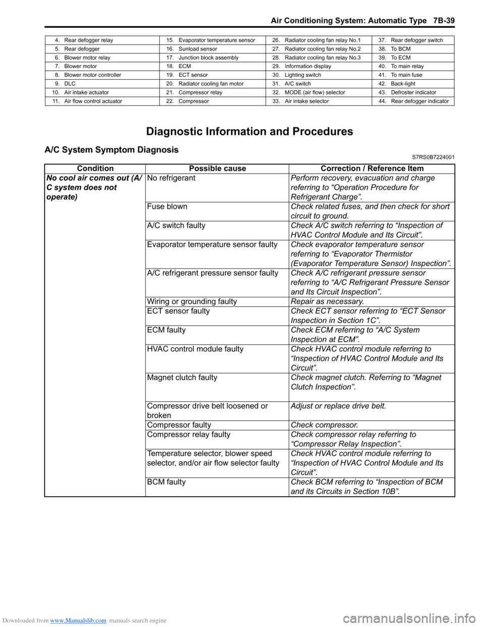
A/C System Symptom DiagnosisS7RS0B7224001
4. Rear defogger relay 15. Evaporator temperature sensor 26. Radiator cooling fan relay No.1 37. Rear defogger switch
5. Rear defogger 16. Sunload sensor 27. Radiator cooling fan relay No.2 38. To BCM
6. Blower motor relay 17. Junction block assembly 28. Radiator cooling fan relay No.3 39. To ECM
7. Blower motor 18. ECM 29. Information display 40. To main relay
8. Blower motor controller 19. ECT sensor 30. Lighting switch 41. To main fuse
9. DLC 20. Radiator cooling fan motor 31. A/C switch 42. Back-light
10. Air intake actuator 21. Compressor relay 32. MODE (air flow) selector 43. Defroster indicator 11. Air flow control actuator 22. Compressor 33. Air intake selector 44. Rear defogger indicator
Condition Possible cause Correction / Reference Item
No cool air comes out (A/
C system does not
operate) No refrigerant
Perform recovery, evacuation and charge
referring to “Operation Procedure for
Refrigerant Charge”.
Fuse blown Check related fuses, and then check for short
circuit to ground.
A/C switch faulty Check A/C switch referring to “Inspection of
HVAC Control Module and Its Circuit”.
Evaporator temperature sensor faulty Check evaporator temperature sensor
referring to “Evaporator Thermistor
(Evaporator Temperature Sensor) Inspection”.
A/C refrigerant pressure sensor faulty Check A/C refrigerant pressure sensor
referring to “A/C Refrigerant Pressure Sensor
and Its Circuit Inspection”.
Wiring or grounding faulty Repair as necessary.
ECT sensor faulty Check ECT sensor referring to “ECT Sensor
Inspection in Section 1C”.
ECM faulty Check ECM referring to “A/C System
Inspection at ECM”.
HVAC control module faulty Check HVAC control module referring to
“Inspection of HVAC Control Module and Its
Circuit”.
Magnet clutch faulty Check magnet clutch. Referring to “Magnet
Clutch Inspection”.
Compressor drive belt loosened or
broken Adjust or replace drive belt.
Compressor faulty Check compressor.
Compressor relay faulty Check compressor relay referring to
“Compressor Relay Inspection”.
Temperature selector, blower speed
selector, and/or air flow selector faulty Check HVAC control module referring to
“Inspection of HVAC Control Module and Its
Circuit”.
BCM faulty Check BCM referring to “Inspection of BCM
and its Circuits in Section 10B”.
Page 988 of 1496
Downloaded from www.Manualslib.com manuals search engine 7B-40 Air Conditioning System: Automatic Type
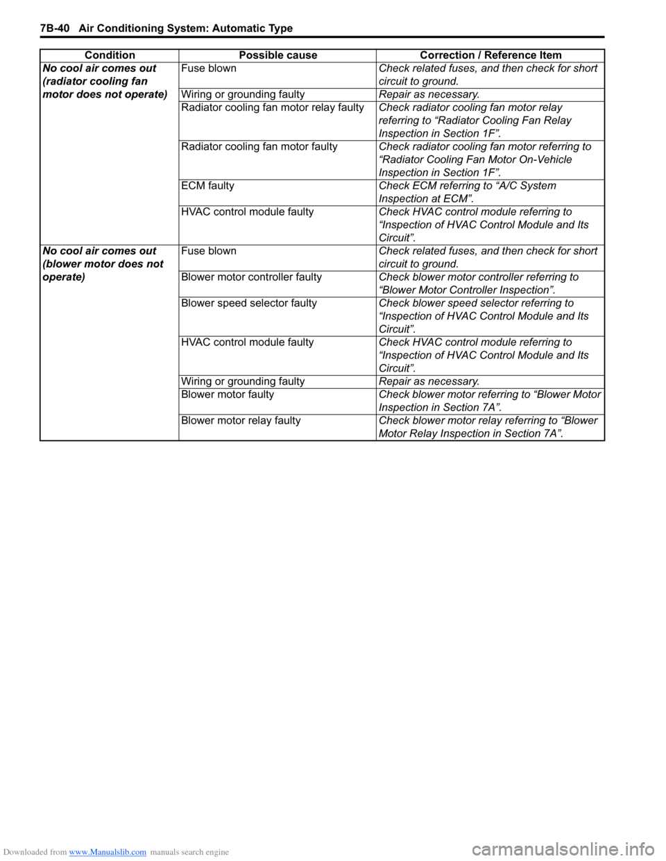
No cool air comes out
(radiator cooling fan
motor does not operate)Fuse blown
Check related fuses, and then check for short
circuit to ground.
Wiring or grounding faulty Repair as necessary.
Radiator cooling fan motor relay faulty Check radiator cooling fan motor relay
referring to “Radiator Cooling Fan Relay
Inspection in Section 1F”.
Radiator cooling fan motor faulty Check radiator cooling fan motor referring to
“Radiator Cooling Fan Motor On-Vehicle
Inspection in Section 1F”.
ECM faulty Check ECM referring to “A/C System
Inspection at ECM”.
HVAC control module faulty Check HVAC control module referring to
“Inspection of HVAC Control Module and Its
Circuit”.
No cool air comes out
(blower motor does not
operate) Fuse blown
Check related fuses, and then check for short
circuit to ground.
Blower motor controller faulty Check blower motor controller referring to
“Blower Motor Controller Inspection”.
Blower speed selector faulty Check blower speed selector referring to
“Inspection of HVAC Control Module and Its
Circuit”.
HVAC control module faulty Check HVAC control module referring to
“Inspection of HVAC Control Module and Its
Circuit”.
Wiring or grounding faulty Repair as necessary.
Blower motor faulty Check blower motor referring to “Blower Motor
Inspection in Section 7A”.
Blower motor relay faulty Check blower motor relay referring to “Blower
Motor Relay Inspection in Section 7A”.
Condition Possible cause Correction / Reference Item
Page 1016 of 1496
Downloaded from www.Manualslib.com manuals search engine 7B-68 Air Conditioning System: Automatic Type
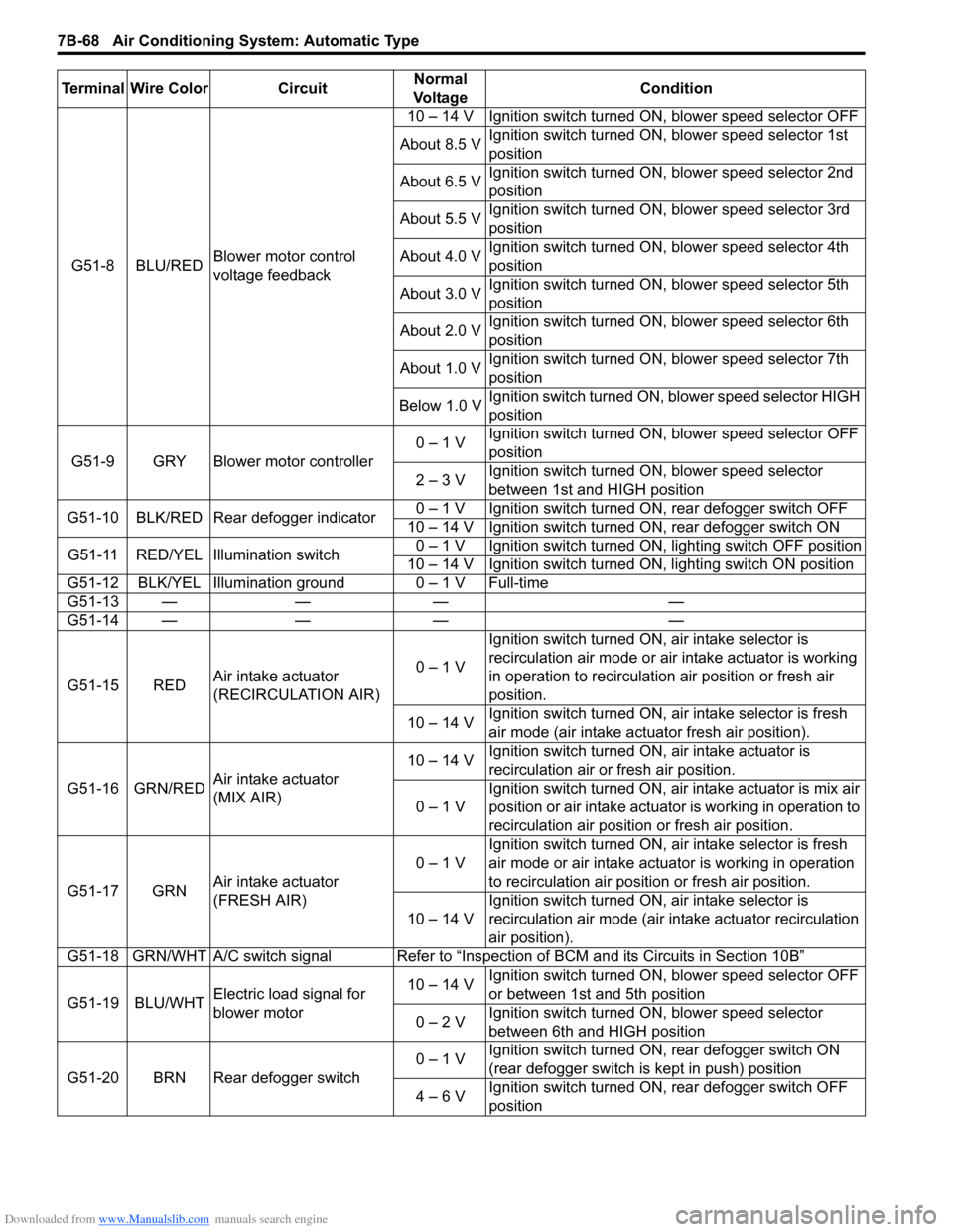
G51-8 BLU/REDBlower motor control
voltage feedback 10 – 14 V Ignition switch turned ON, blower speed selector OFF
About 8.5 V Ignition switch turned ON, blower speed selector 1st
position
About 6.5 V Ignition switch turned ON, blower speed selector 2nd
position
About 5.5 V Ignition switch turned ON, blower speed selector 3rd
position
About 4.0 V Ignition switch turned ON, blower speed selector 4th
position
About 3.0 V Ignition switch turned ON, blower speed selector 5th
position
About 2.0 V Ignition switch turned ON, blower speed selector 6th
position
About 1.0 V Ignition switch turned ON, blower speed selector 7th
position
Below 1.0 V Ignition switch turned ON, blower speed selector HIGH
position
G51-9 GRY Blower motor controller 0 – 1 V
Ignition switch turned ON, blower speed selector OFF
position
2 – 3 V Ignition switch turned ON, blower speed selector
between 1st and HIGH position
G51-10 BLK/RED Rear defogger indicator 0 – 1 V Ignition switch turned ON, rear defogger switch OFF
10 – 14 V Ignition switch turned ON, rear defogger switch ON
G51-11 RED/YEL Illumination switch 0 – 1 V Ignition switch turned ON, lighting switch OFF position
10 – 14 V Ignition switch turned ON, lighting switch ON position
G51-12 BLK/YEL Illumination ground 0 – 1 V Full-time
G51-13 — — — —
G51-14 — — — —
G51-15 RED Air intake actuator
(RECIRCULATION AIR) 0 – 1 VIgnition switch turned ON, air intake selector is
recirculation air mode or air intake actuator is working
in operation to recirculation air position or fresh air
position.
10 – 14 V Ignition switch turned ON, ai
r intake selector is fresh
air mode (air intake actuator fresh air position).
G51-16 GRN/RED Air intake actuator
(MIX AIR) 10 – 14 V
Ignition switch turned ON, air intake actuator is
recirculation air or fresh air position.
0 – 1 V Ignition switch turned ON, air intake actuator is mix air
position or air intake actuator is working in operation to
recirculation air position or fresh air position.
G51-17 GRN Air intake actuator
(FRESH AIR) 0 – 1 V
Ignition switch turned ON, ai
r intake selector is fresh
air mode or air intake actuator is working in operation
to recirculation air position or fresh air position.
10 – 14 V Ignition switch turned ON, air intake selector is
recirculation air mode (air intake actuator recirculation
air position).
G51-18 GRN/WHT A/C switch signal Refer to “Inspe ction of BCM and its Circuits in Section 10B”
G51-19 BLU/WHT Electric load signal for
blower motor 10 – 14 V
Ignition switch turned ON, blower speed selector OFF
or between 1st and 5th position
0 – 2 V Ignition switch turned ON, blower speed selector
between 6th and HIGH position
G51-20 BRN Rear defogger switch 0 – 1 V
Ignition switch turned ON, rear defogger switch ON
(rear defogger switch is kept in push) position
4 – 6 V Ignition switch turned ON, rear defogger switch OFF
position
Terminal Wire Color Circuit
Normal
Vo l ta g e Condition
Page 1021 of 1496
Downloaded from www.Manualslib.com manuals search engine Air Conditioning System: Automatic Type 7B-73
HVAC Unit Removal and InstallationS7RS0B7226003
Refer to “HVAC Unit Removal and Installation”.
Temperature Control Actuator Removal and
Installation
S7RS0B7226004
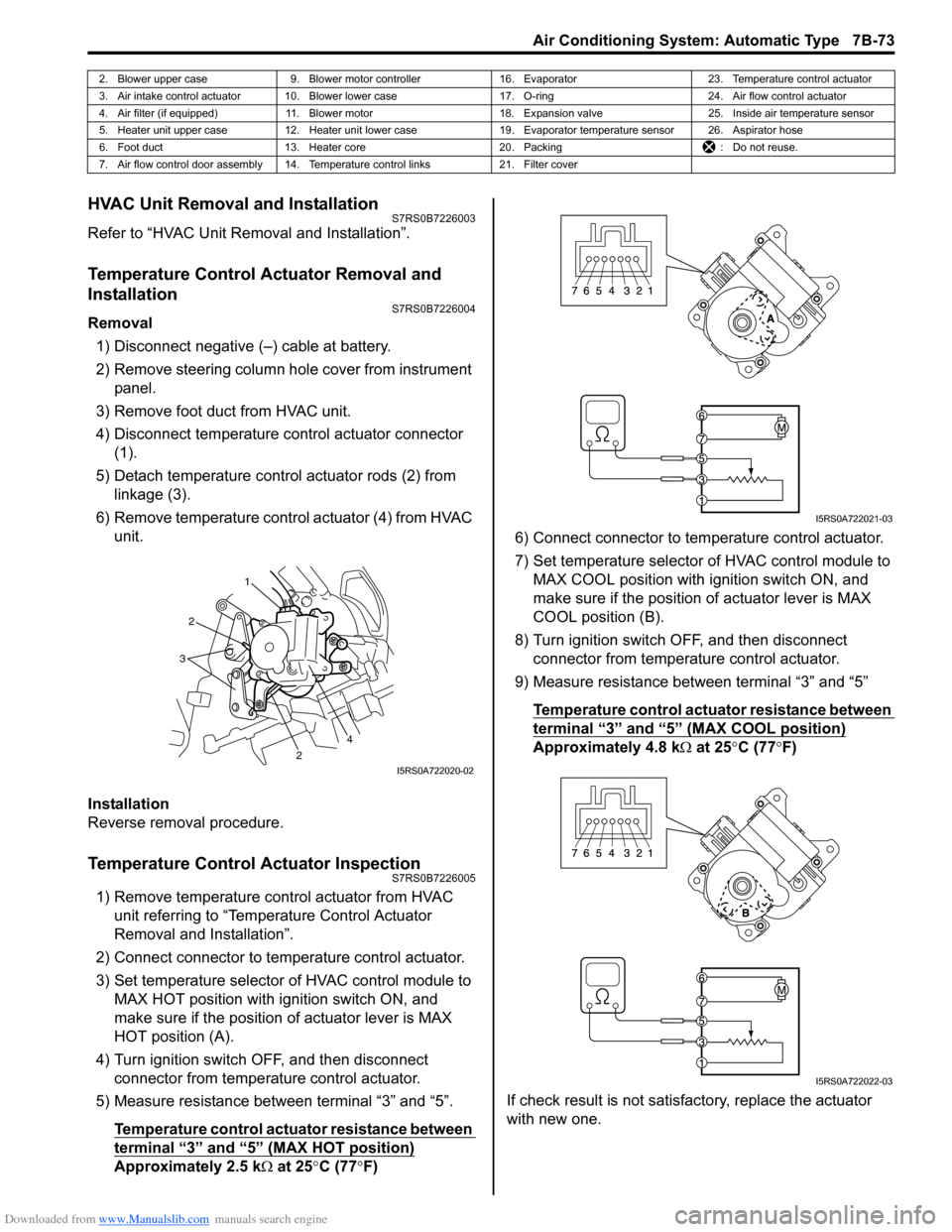
Removal1) Disconnect negative (–) cable at battery.
2) Remove steering column hol e cover from instrument
panel.
3) Remove foot duct from HVAC unit.
4) Disconnect temperature control actuator connector (1).
5) Detach temperature control actuator rods (2) from linkage (3).
6) Remove temperature control actuator (4) from HVAC unit.
Installation
Reverse removal procedure.
Temperature Control Actuator InspectionS7RS0B7226005
1) Remove temperature control actuator from HVAC unit referring to “Temperature Control Actuator
Removal and Installation”.
2) Connect connector to temperature control actuator.
3) Set temperature selector of HVAC control module to MAX HOT position with ignition switch ON, and
make sure if the position of actuator lever is MAX
HOT position (A).
4) Turn ignition switch OFF, and then disconnect connector from temperature control actuator.
5) Measure resistance between terminal “3” and “5”.
Temperature control actuator resistance between
terminal “3” and “5” (MAX HOT position)
Approximately 2.5 k Ω at 25 °C (77 °F) 6) Connect connector to tem
perature control actuator.
7) Set temperature selector of HVAC control module to MAX COOL position with ignition switch ON, and
make sure if the position of actuator lever is MAX
COOL position (B).
8) Turn ignition switch OFF, and then disconnect connector from temperature control actuator.
9) Measure resistance between terminal “3” and “5”
Temperature control actuator resistance between
terminal “3” and “5” (MAX COOL position)
Approximately 4.8 k Ω at 25 °C (77 °F)
If check result is not satisfactory, replace the actuator
with new one.
2. Blower upper case 9. Blower motor controller 16. Evaporator 23. Temperature control actuator
3. Air intake control actuator 10. Blower lower case 17. O-ring24. Air flow control actuator
4. Air filter (if equipped) 11. Blower motor 18. Expansion valve25. Inside air temperature sensor
5. Heater unit upper case 12. Heater unit lower case 19. Evaporator temperature sensor 26. Aspirator hose
6. Foot duct 13. Heater core 20. Packing : Do not reuse.
7. Air flow control door assembly 14. Temperature control links 21. Filter cover
1
2
2
3
4
I5RS0A722020-02
I5RS0A722021-03
I5RS0A722022-03
Page 1024 of 1496
Downloaded from www.Manualslib.com manuals search engine 7B-76 Air Conditioning System: Automatic Type
Actuator Linkage InspectionS7RS0B7226010
• Check if each actuator linkage operates smoothly.
• Check actuator rod for bend.
• Check each actuator linkage for breakage.
• Make sure if there is not any obstruction in operating range of actuator linkage.
If any malfunction is found, repair or replace faulty
part(s).
Blower Motor Controller Removal and
Installation
S7RS0B7226011
Refer to “Blower Motor Resistor Removal and
Installation in Section 7A”.
Blower Motor Controller InspectionS7RS0B7226012
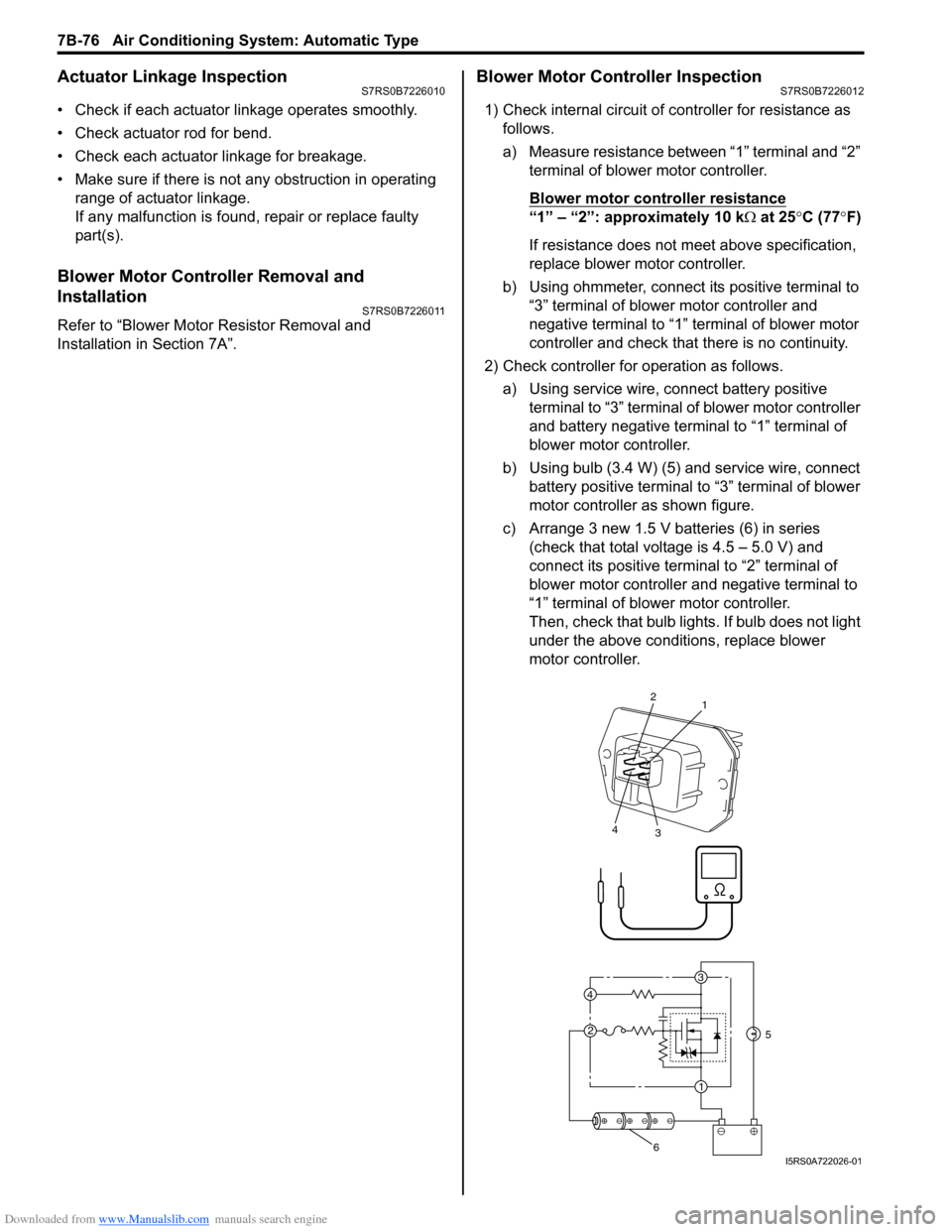
1) Check internal circuit of controller for resistance as follows.
a) Measure resistance between “1” terminal and “2” terminal of blower motor controller.
Blower motor cont roller resistance
“1” – “2”: approximately 10 k Ω at 25 °C (77 °F)
If resistance does not meet above specification,
replace blower motor controller.
b) Using ohmmeter, connect its positive terminal to “3” terminal of blower motor controller and
negative terminal to “1” terminal of blower motor
controller and check that there is no continuity.
2) Check controller for operation as follows. a) Using service wire, connect battery positive terminal to “3” terminal of blower motor controller
and battery negative terminal to “1” terminal of
blower motor controller.
b) Using bulb (3.4 W) (5) and service wire, connect battery positive terminal to “3” terminal of blower
motor controller as shown figure.
c) Arrange 3 new 1.5 V batteries (6) in series (check that total voltage is 4.5 – 5.0 V) and
connect its positive term inal to “2” terminal of
blower motor controller and negative terminal to
“1” terminal of blower motor controller.
Then, check that bulb lights. If bulb does not light
under the above conditions, replace blower
motor controller.
3
1
2
4
2
1
3
4
5
6I5RS0A722026-01
Page 1189 of 1496
Downloaded from www.Manualslib.com manuals search engine Wiring Systems: 9A-18
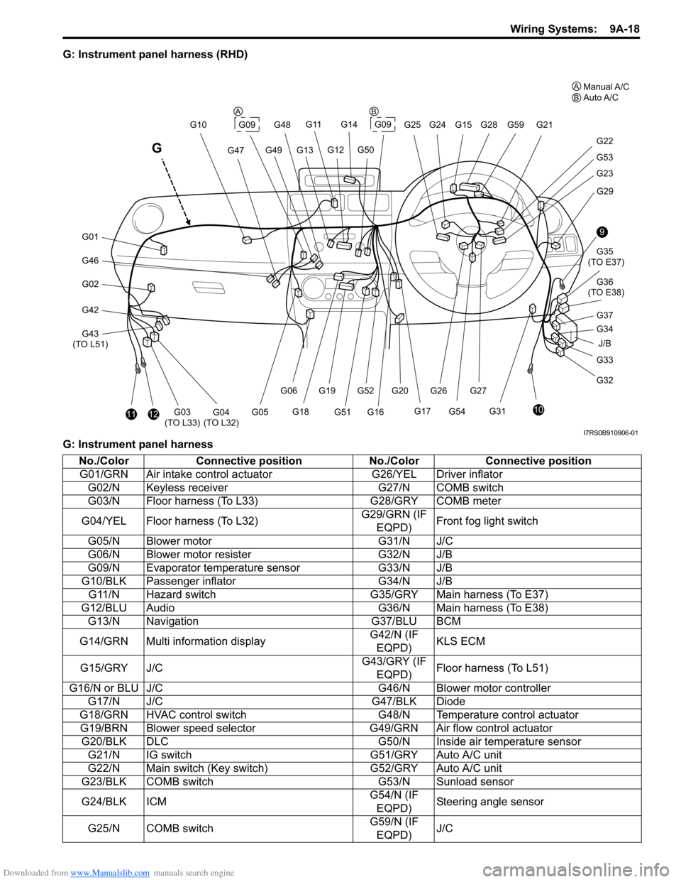
G: Instrument panel harness (RHD)
G: Instrument panel harness
J/B
9
10
G33
G32 G34 G35
(TO E37)
G36
(TO E38)
G31 G29
G23
G53
G22
G21
G28G59
G20G52G27
G54
G261112G03
(TO L33)G04
(TO L32)
G46
G01
G02
G42
G43
(TO L51) G10
G47
G11
G13G49
G14
G09G25 G24G15
G12G50
G48
G17
G16G51
G19
G18
G06
G05
G
G09
G37
A
BManual A/C
Auto A/C
AB
I7RS0B910906-01
No./Color Connective position No./ColorConnective position
G01/GRN Air intake control ac tuatorG26/YEL Driver inflator
G02/N Keyless receiver G27/N COMB switch
G03/N Floor harness (To L33) G28/GRY COMB meter
G04/YEL Floor harness (To L32) G29/GRN (IF
EQPD) Front fog light switch
G05/N Blower motor G31/N J/C
G06/N Blower motor resister G32/N J/B
G09/N Evaporator temperature sensor G33/N J/B
G10/BLK Passenger inflator G34/N J/B
G11/N Hazard switch G35/GRY Main harness (To E37)
G12/BLU Audio G36/N Main harness (To E38)
G13/N Navigation G37/BLU BCM
G14/GRN Multi information display G42/N (IF
EQPD) KLS ECM
G15/GRY J/C G43/GRY (IF
EQPD) Floor harness (To L51)
G16/N or BLU J/C G46/N Blower motor controller
G17/N J/C G47/BLK Diode
G18/GRN HVAC control switch G48/N Temperature control actuator
G19/BRN Blower speed selector G49/GRN Air flow control actuator
G20/BLK DLC G50/N Inside air temperature sensor
G21/N IG switch G51/GRY Auto A/C unit
G22/N Main switch (Key switch) G52/GRY Auto A/C unit
G23/BLK COMB switch G53/N Sunload sensor
G24/BLK ICM G54/N (IF
EQPD) Steering angle sensor
G25/N COMB switch G59/N (IF
EQPD) J/C