Tighten SUZUKI SWIFT 2007 2.G Service Workshop Manual
[x] Cancel search | Manufacturer: SUZUKI, Model Year: 2007, Model line: SWIFT, Model: SUZUKI SWIFT 2007 2.GPages: 1496, PDF Size: 34.44 MB
Page 1 of 1496
Downloaded from www.Manualslib.com manuals search engine Suzuki Swift Sport (RS416)
2004-2008 Service/Repair Manual
This Service Manual has been prepared with the latest service information available at the time
of publication. It is subdivided into various group categories and each section contains diagnostic,
disassembly, repair and installation procedures along with complete specifications and tightening
references. Please read this manual carefully before proceeding, as incorrect service procedures
may result in injury or death to service personnel or to the operator’s of the vehicle.
Page 21 of 1496
Downloaded from www.Manualslib.com manuals search engine Table of Contents 0- i
0
Section 0
CONTENTS
General Information
General Information ................................ 0A-1
General Description ............................................. 0A-1
Abbreviations ...................................................... 0A-1
Symbols .............................................................. 0A-2
Wire Color Symbols ............................................ 0A-2
Fasteners Information ......................................... 0A-3
Vehicle Lifting Points ........................................... 0A-5
Engine Supporting Points ................................... 0A-7
Vehicle Identification Number ............................. 0A-7
Engine Identification Number .............................. 0A-7
Transmission Identification Number .................... 0A-7
Component Locatio n ........................................... 0A-8
Warning, Caution and Information Labels Location ............................................................ 0A-8
Maintenance and Lubricat ion ................. 0B-1
Precautions........................................................... 0B-1
Precautions for Maintenance and Lubrication ..... 0B-1
Scheduled Maintenance ...................................... 0B-1 Maintenance Schedule under Normal Driving Conditions ......................................................... 0B-1
Maintenance Recommended under Severe Driving Conditions ............................................. 0B-2
Repair Instructions .............................................. 0B-3 Accessory Drive Belt Inspection.......................... 0B-3
Accessory Drive Belt Repl acement ..................... 0B-4
Valve Lash (Clearance) Inspection ..................... 0B-4
Engine Oil and Filter Change .............................. 0B-4
Engine Coolant Change ...... ................................ 0B-5
Exhaust System Inspection ................................. 0B-6
Spark Plug Replacement .................................... 0B-6
Air Cleaner Filter Inspection ................................ 0B-6
Air Cleaner Filter Replac ement ........................... 0B-6 Fuel Lines and Connections Inspection .............. 0B-6
Fuel Filter Replacement ...................................... 0B-7
Fuel Tank Inspection ........................................... 0B-7
PCV Valve Inspection ......................................... 0B-7
Fuel Evaporative Emission Control System
Inspection .......................................................... 0B-7
Brake Discs and Pads Inspection ....................... 0B-7
Brake Hoses and Pipes Inspection ..................... 0B-7
Brake Fluid Inspection......................................... 0B-8
Brake Fluid Replacement .................................... 0B-8
Brake Lever and Cable Inspection ...................... 0B-8
Clutch Fluid Inspection ........................................ 0B-8
Tires Inspection ................................................... 0B-9
Wheel Discs Inspection ....................................... 0B-9
Wheel Bearing Inspection ................................... 0B-9
Suspension System Inspection ........................... 0B-9
Steering System Inspection .............................. 0B-10
Drive Shaft (Axle) Boots Inspection .................. 0B-10
Manual Transaxle Oil Inspection ....................... 0B-10
Manual Transaxle Oil Replacement .................. 0B-10
Automatic Transaxle Fluid Level Inspection...... 0B-11
Automatic Transaxle Fluid Replacement .......... 0B-11
Automatic Transaxle Fluid Cooler Hose Inspection ........................................................ 0B-11
All Latches, Hinges and Locks Inspection......... 0B-11
HVAC Air Filter (If Equipped) Inspection ........... 0B-12
HVAC Air Filter (If Equipped) Replacement ...... 0B-12
Final Inspection for Maint enance Service ......... 0B-12
Specifications .................... .................................0B-13
Tightening Torque Specifications ...................... 0B-13
Special Tools and Equipmen t ...........................0B-13
Recommended Fluids and Lubricants............... 0B-13
Special Tool ...................................................... 0B-14
Page 23 of 1496
Downloaded from www.Manualslib.com manuals search engine General Information: 0A-2
SAS: Steering Angle Sensor
SDM: Sensing and Diagnostic Module (Air Bag Controller, Air bag Control Module)
SDT: Smart Diagnostic Tester
SFI: Sequential Multipor t Fuel Injection
SOHC: Single Over Head Camshaft
T:
TBI: Throttle Body Fuel Injection (Single-Point Fuel
Injection, SPI)
TCC: Torque Converter Clutch
TCM: Transmission Control Module (A/T Controller, A/T
Control Module)
TDC: Top Dead Center
TP Sensor: Throttle Position Sensor TVV:
Thermal Vacuum Valve (Thermal Vacuum
Switching Valve, TVSV, Bi metal Vacuum Switching
Valve, BVSV)
TWC: Three Way Catalytic Converter (Three Way
Catalyst)
2WD: 2 Wheel Drive
U:
USB: Universal Serial Bus
V:
VIN: Vehicle Identification Number
VSS: Vehicle Speed Sensor
VVT: Variable Valve Timing (Camshaft Position Control)
W:
WU-OC: Warm Up Oxidation Catalytic Converter
WU-TWC: Warm Up Three Way Catalytic Converter
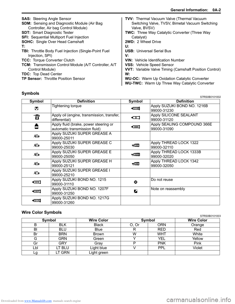
SymbolsS7RS0B0101002
Wire Color SymbolsS7RS0B0101003
Symbol Definition SymbolDefinition
Tightening torque Apply SUZUKI BOND NO. 1216B
99000-31230
Apply oil (engine, transmission, transfer,
differential) Apply SILICONE SEALANT
99000-31120
Apply fluid (brake, power steering or
automatic transmission fluid) Apply SEALING COMPOUND 366E
99000-31090
Apply SUZUKI SUPER GREASE A
99000-25011
Apply SUZUKI SUPER GREASE C
99000-25030 Apply THREAD LOCK 1322
99000-32110
Apply SUZUKI SUPER GREASE E
99000-25050 Apply THREAD LOCK 1333B
99000-32020
Apply SUZUKI SUPER GREASE H
99000-25121 Apply THREAD LOCK 1342
99000-32050
Apply SUZUKI SUPER GREASE I
99000-25210
Apply SUZUKI BOND NO. 1215
99000-31110 Do not reuse
Apply SUZUKI BO ND NO. 1207F
99000-31250 Note on reassembly
Apply SUZUKI BO ND NO. 1217G
99000-31260
Symbol Wire Color SymbolWire Color
B BLK Black O, Or ORN Orange
Bl BLU Blue RRED Red
Br BRN Brown WWHT White
G GRN Green YYEL Yellow
Gr GRY Gray PPNK Pink
Lbl LT BLU Light blueVPPL Violet
Lg LT GRN Light green
Page 24 of 1496
Downloaded from www.Manualslib.com manuals search engine 0A-3 General Information:
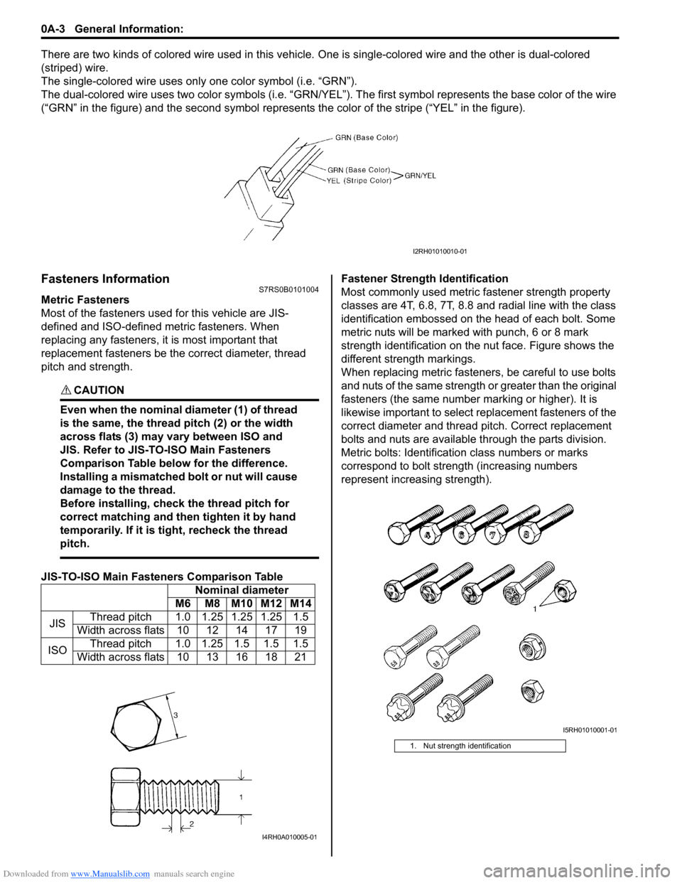
There are two kinds of colored wire used in this vehicle. One is single-colored wire and the other is dual-colored
(striped) wire.
The single-colored wire uses only one color symbol (i.e. “GRN”).
The dual-colored wire uses two color sy mbols (i.e. “GRN/YEL”). The first symbo l represents the base color of the wire
(“GRN” in the figure) and the second symbol represents the color of the stripe (“YEL” in the figure).
Fasteners InformationS7RS0B0101004
Metric Fasteners
Most of the fasteners used for this vehicle are JIS-
defined and ISO-defined metric fasteners. When
replacing any fasteners, it is most important that
replacement fasteners be the correct diameter, thread
pitch and strength.
CAUTION!
Even when the nominal diameter (1) of thread
is the same, the thread pitch (2) or the width
across flats (3) may vary between ISO and
JIS. Refer to JIS-TO-ISO Main Fasteners
Comparison Table below for the difference.
Installing a mismatched bolt or nut will cause
damage to the thread.
Before installing, check the thread pitch for
correct matching and then tighten it by hand
temporarily. If it is tight, recheck the thread
pitch.
JIS-TO-ISO Main Fasteners Comparison Table Fastener Strength Identification
Most commonly used metric fastener strength property
classes are 4T, 6.8, 7T, 8.8 and radial line with the class
identification embossed on the head of each bolt. Some
metric nuts will be marked with punch, 6 or 8 mark
strength identification on the nut face. Figure shows the
different strength markings.
When replacing metric fasteners, be careful to use bolts
and nuts of the same strength or greater than the original
fasteners (the same number marking or higher). It is
likewise important to select replacement fasteners of the
correct diameter and thread
pitch. Correct replacement
bolts and nuts are available through the parts division.
Metric bolts: Identification class numbers or marks
correspond to bolt strength (increasing numbers
represent increasing strength).
I2RH01010010-01
Nominal diameter
M6 M8 M10 M12 M14
JIS Thread pitch 1.0 1.25 1.25 1.25 1.5
Width across flats 10 12 14 17 19
ISO Thread pitch 1.0 1.25 1.5 1.5 1.5
Width across flats 10 13 16 18 21
I4RH0A010005-01
1. Nut strength identification
I5RH01010001-01
Page 25 of 1496
Downloaded from www.Manualslib.com manuals search engine General Information: 0A-4
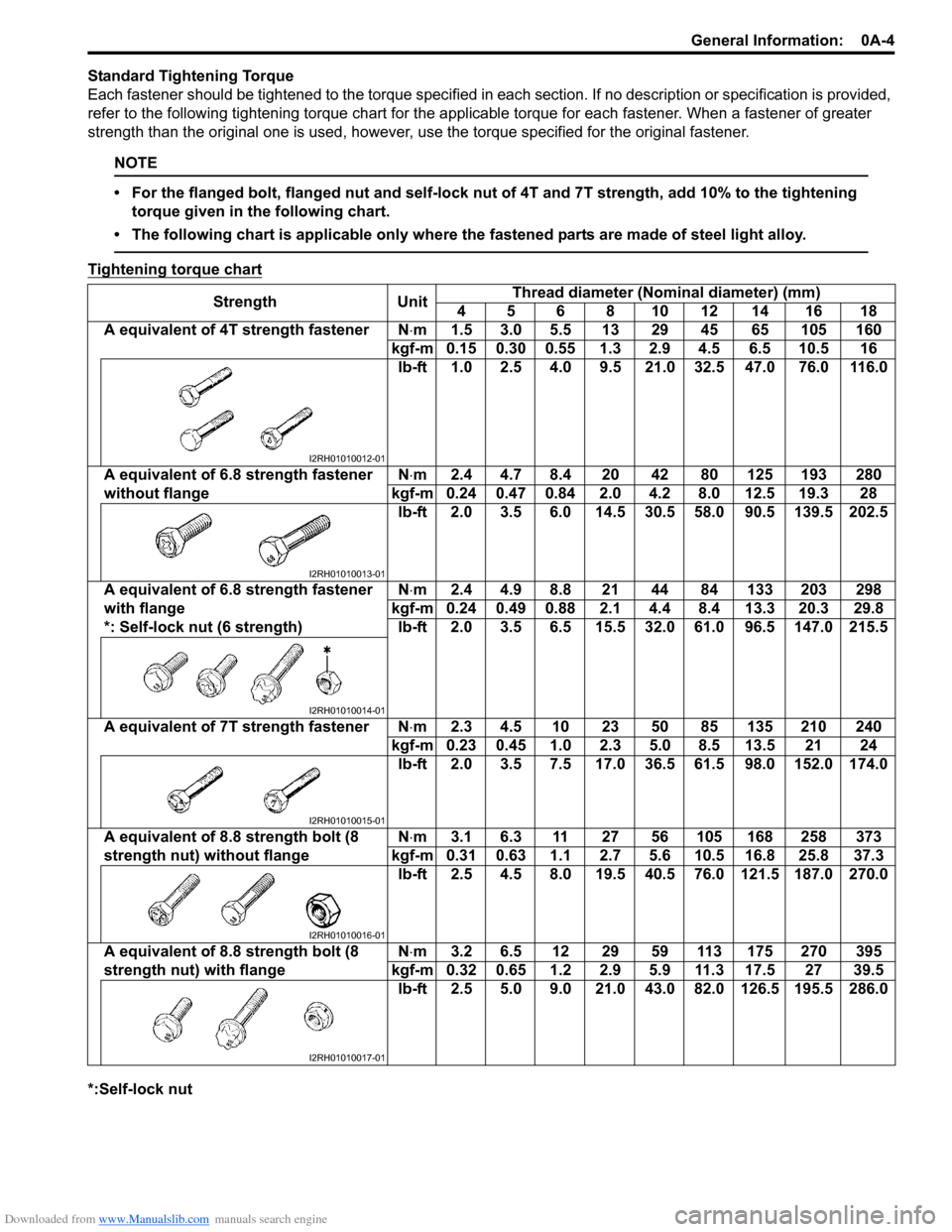
Standard Tightening Torque
Each fastener should be tightened to the torque specified in each section. If no description or specification is provided,
refer to the following tightening torque chart for the applicable torque for each fastener. When a fastener of greater
strength than the original one is used, however, use the torque specified for the original fastener.
NOTE
• For the flanged bolt, flanged nut and self-lock nut of 4T and 7T strength, add 10% to the tightening torque given in the following chart.
• The following chart is applicable only where the fastened parts are made of steel light alloy.
Tightening torque chart
*:Self-lock nut Strength Unit
Thread diameter (Nominal diameter) (mm)
4 5 6 8 10 12 14 16 18
A equivalent of 4T strength fastener N⋅ m 1.5 3.0 5.5 13 29 45 65 105 160
kgf-m 0.15 0.30 0.55 1.3 2.9 4.5 6.5 10.5 16 lb-ft 1.0 2.5 4.0 9.5 21.0 32.5 47.0 76.0 116.0
A equivalent of 6.8 strength fastener
without flange N
⋅m 2.4 4.7 8.4 20 42 80 125 193 280
kgf-m 0.24 0.47 0.84 2.0 4.2 8.0 12.5 19.3 28 lb-ft 2.0 3.5 6.0 14.5 30.5 58.0 90.5 139.5 202.5
A equivalent of 6.8 strength fastener
with flange
*: Self-lock nut (6 strength) N
⋅m 2.4 4.9 8.8 21 44 84 133 203 298
kgf-m 0.24 0.49 0.88 2.1 4.4 8.4 13.3 20.3 29.8 lb-ft 2.0 3.5 6.5 15.5 32.0 61.0 96.5 147.0 215.5
A equivalent of 7T strength fastener N⋅ m 2.3 4.5 10 23 50 85 135 210 240
kgf-m 0.23 0.45 1.0 2.3 5.0 8.5 13.5 21 24 lb-ft 2.0 3.5 7.5 17.0 36.5 61.5 98.0 152.0 174.0
A equivalent of 8.8 strength bolt (8
strength nut) without flange N
⋅m 3.1 6.3 11 27 56 105 168 258 373
kgf-m 0.31 0.63 1.1 2.7 5.6 10.5 16.8 25.8 37.3 lb-ft 2.5 4.5 8.0 19.5 40.5 76.0 121.5 187.0 270.0
A equivalent of 8.8 strength bolt (8
strength nut) with flange N
⋅m 3.2 6.5 12 29 59 113 175 270 395
kgf-m 0.32 0.65 1.2 2.9 5.9 11.3 17.5 27 39.5 lb-ft 2.5 5.0 9.0 21.0 43.0 82.0 126.5 195.5 286.0
I2RH01010012-01
I2RH01010013-01
I2RH01010014-01
I2RH01010015-01
I2RH01010016-01
I2RH01010017-01
Page 33 of 1496
Downloaded from www.Manualslib.com manuals search engine Maintenance and Lubrication: 0B-3
NOTE
• “I”: Inspect and correct or replace if necessary
• “R”: Replace or change
• *1: Inspect or replace more frequently if the vehicle is used under dusty conditions.
• *2: Clean or replace more frequently if the air from the air conditioning decreases.
Repair Instructions
Accessory Drive Belt InspectionS7RS0B0206001
WARNING!
All inspection and replacement are to be
performed with ENGINE NOT RUNNING.
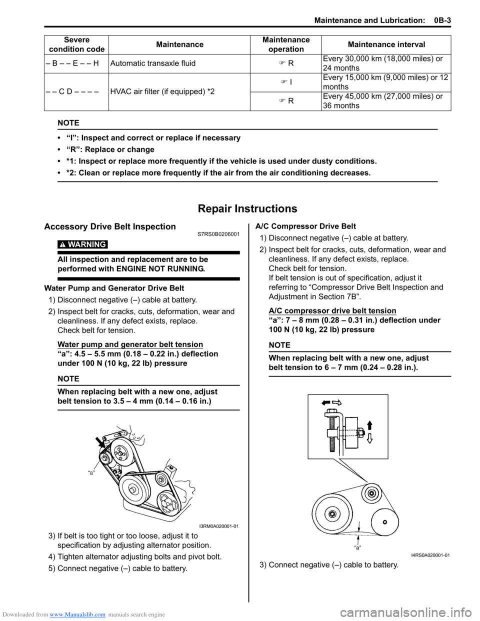
Water Pump and Generator Drive Belt1) Disconnect negative (–) cable at battery.
2) Inspect belt for cracks, cu ts, deformation, wear and
cleanliness. If any defect exists, replace.
Check belt for tension.
Water pump and generator belt tension
“a”: 4.5 – 5.5 mm (0.18 – 0.22 in.) deflection
under 100 N (10 kg, 22 lb) pressure
NOTE
When replacing belt with a new one, adjust
belt tension to 3.5 – 4 mm (0.14 – 0.16 in.)
3) If belt is too tight or too loose, adjust it to
specification by adjusting alternator position.
4) Tighten alternator adjusting bolts and pivot bolt.
5) Connect negative (–) cable to battery. A/C Compressor Drive Belt
1) Disconnect negative (–) cable at battery.
2) Inspect belt for cracks, cuts, deformation, wear and cleanliness. If any defect exists, replace.
Check belt for tension.
If belt tension is out of specification, adjust it
referring to “Compressor Dr ive Belt Inspection and
Adjustment in Section 7B”.
A/C compressor drive belt tension
“a”: 7 – 8 mm (0.28 – 0.31 in.) deflection under
100 N (10 kg, 22 lb) pressure
NOTE
When replacing belt with a new one, adjust
belt tension to 6 – 7 mm (0.24 – 0.28 in.).
3) Connect negative (–) cable to battery.
– B – – E – – H Automatic transaxle fluid
�) R Every 30,000 km (18,000 miles) or
24 months
– – C D – – – – HVAC air filter (if equipped) *2 �)
I Every 15,000 km (9,000 miles) or 12
months
�) R Every 45,000 km (27,000 miles) or
36 months
Severe
condition code MaintenanceMaintenance
operation Maintenance interval
I3RM0A020001-01
I4RS0A020001-01
Page 34 of 1496
Downloaded from www.Manualslib.com manuals search engine 0B-4 Maintenance and Lubrication:
Accessory Drive Belt ReplacementS7RS0B0206002
Water Pump and Generator Drive Belt
Replace belt with new one referring to “Water Pump /
Generator Drive Belt Removal and Installation in Section
1J”.
A/C Compressor Drive Belt
Replace belt with new one referring to “Compressor
Drive Belt Removal and Inst allation in Section 7B”.
Valve Lash (Clearance) InspectionS7RS0B0206003
Inspect intake and exhaust valve lash and adjust as
necessary.
Refer to “Valve Lash (Clearance) Inspection in Section
1D” for valve lash inspection and adjustment procedure.
Engine Oil and Filter ChangeS7RS0B0206004
WARNING!
• New and used engine oil can be
hazardous.
Be sure to read “WARNING” in “General
Precautions in Section 00” and observe
what is written there.
• Step 1) – 7) outlined below must be performed with ENGINE NOT RUNNING.
For Step 8), be sure to have adequate
ventilation while engine is running.
Before draining engine oil, check engine for oil leakage.
If any evidence of leakage is found, make sure to correct
defective part before proceeding to the following work.
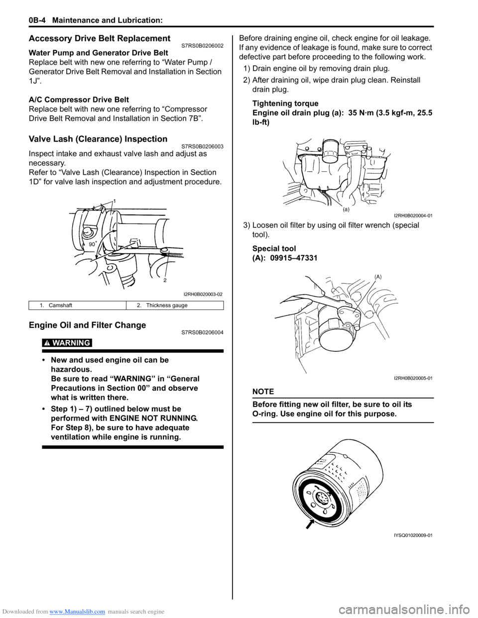
1) Drain engine oil by removing drain plug.
2) After draining oil, wipe drain plug clean. Reinstall drain plug.
Tightening torque
Engine oil drain plug (a): 35 N·m (3.5 kgf-m, 25.5
lb-ft)
3) Loosen oil filter by using oil filter wrench (special
tool).
Special tool
(A): 09915–47331
NOTE
Before fitting new oil filter, be sure to oil its
O-ring. Use engine oil for this purpose.
1. Camshaft 2. Thickness gauge
I2RH0B020003-02
I2RH0B020004-01
I2RH0B020005-01
IYSQ01020009-01
Page 35 of 1496
Downloaded from www.Manualslib.com manuals search engine Maintenance and Lubrication: 0B-5
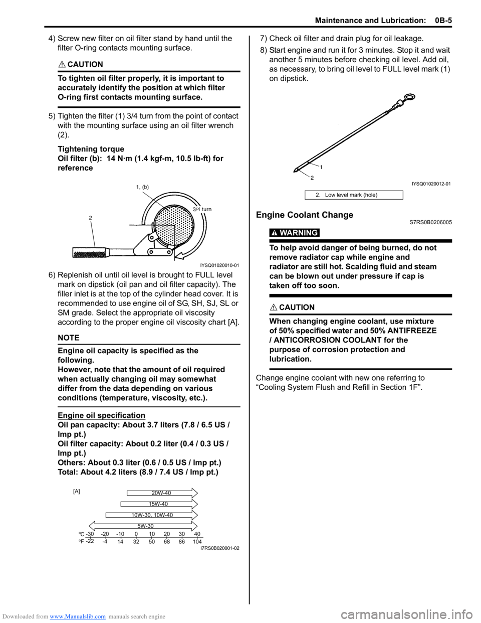
4) Screw new filter on oil filter stand by hand until the filter O-ring contacts mounting surface.
CAUTION!
To tighten oil filter prop erly, it is important to
accurately identify the position at which filter
O-ring first contacts mounting surface.
5) Tighten the filter (1) 3/4 tu rn from the point of contact
with the mounting surface using an oil filter wrench
(2).
Tightening torque
Oil filter (b): 14 N·m (1 .4 kgf-m, 10.5 lb-ft) for
reference
6) Replenish oil until oil leve l is brought to FULL level
mark on dipstick (oil pan and oil filter capacity). The
filler inlet is at the top of the cylinder head cover. It is
recommended to use engine oil of SG, SH, SJ, SL or
SM grade. Select the appropriate oil viscosity
according to the proper engine oil viscosity chart [A].
NOTE
Engine oil capacity is specified as the
following.
However, note that the amount of oil required
when actually changing oil may somewhat
differ from the data depending on various
conditions (temperature, viscosity, etc.).
Engine oil specification
Oil pan capacity: About 3.7 liters (7.8 / 6.5 US /
lmp pt.)
Oil filter capacity: About 0.2 liter (0.4 / 0.3 US /
lmp pt.)
Others: About 0.3 liter (0 .6 / 0.5 US / lmp pt.)
Total: About 4.2 liters (8.9 / 7.4 US / lmp pt.) 7) Check oil filter and drain plug for oil leakage.
8) Start engine and run it for 3 minutes. Stop it and wait
another 5 minutes before checking oil level. Add oil,
as necessary, to bring oil le vel to FULL level mark (1)
on dipstick.
Engine Coolant ChangeS7RS0B0206005
WARNING!
To help avoid danger of being burned, do not
remove radiator cap while engine and
radiator are still hot. Scalding fluid and steam
can be blown out under pressure if cap is
taken off too soon.
CAUTION!
When changing engine coolant, use mixture
of 50% specified water and 50% ANTIFREEZE
/ ANTICORROSION COOLANT for the
purpose of corrosion protection and
lubrication.
Change engine coolant with new one referring to
“Cooling System Flush and Refill in Section 1F”.
IYSQ01020010-01
Co
Fo-30
-22 -20
-4 -10
14 32 50 68 86 104 010203040
5W-30
20W-40
15W-40
10W-30, 10W-40
[A]
I7RS0B020001-02
2. Low level mark (hole)
IYSQ01020012-01
Page 36 of 1496
Downloaded from www.Manualslib.com manuals search engine 0B-6 Maintenance and Lubrication:
Exhaust System InspectionS7RS0B0206006
WARNING!
To avoid danger of being burned, do not
touch exhaust system when it is still hot.
Any service on exhaust system should be
performed when it is cool.
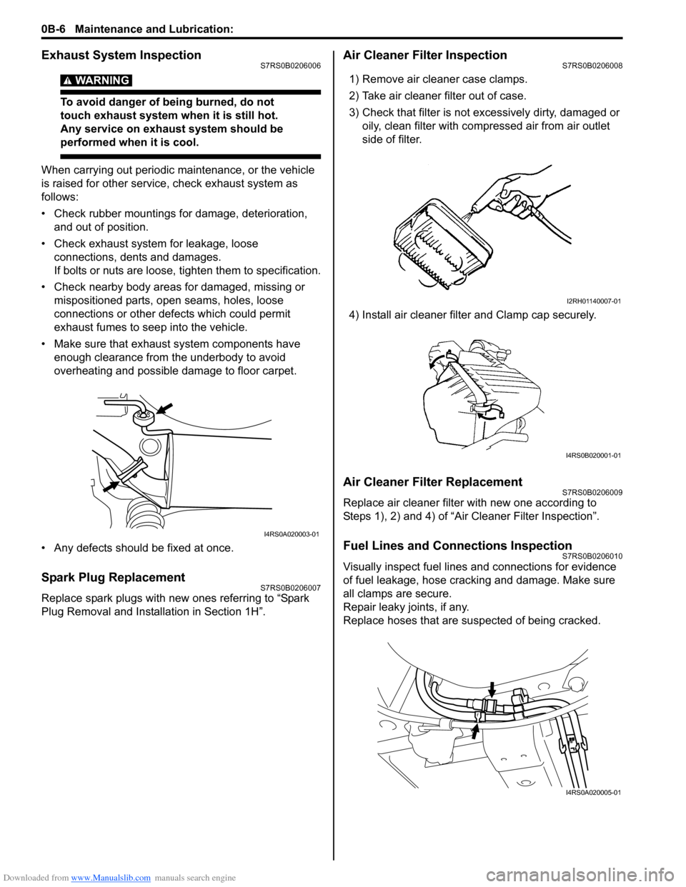
When carrying out periodic maintenance, or the vehicle
is raised for other service, check exhaust system as
follows:
• Check rubber mountings for damage, deterioration, and out of position.
• Check exhaust system for leakage, loose connections, dents and damages.
If bolts or nuts are loose, tighten them to specification.
• Check nearby body areas for damaged, missing or mispositioned parts, ope n seams, holes, loose
connections or other defects which could permit
exhaust fumes to seep into the vehicle.
• Make sure that exhaust system components have enough clearance from the underbody to avoid
overheating and possible damage to floor carpet.
• Any defects should be fixed at once.
Spark Plug ReplacementS7RS0B0206007
Replace spark plugs with new ones referring to “Spark
Plug Removal and Installation in Section 1H”.
Air Cleaner Filter InspectionS7RS0B0206008
1) Remove air cleaner case clamps.
2) Take air cleaner filter out of case.
3) Check that filter is not excessively dirty, damaged or oily, clean filter with compressed air from air outlet
side of filter.
4) Install air cleaner filter and Clamp cap securely.
Air Cleaner Filter ReplacementS7RS0B0206009
Replace air cleaner filter with new one according to
Steps 1), 2) and 4) of “Air Cleaner Filter Inspection”.
Fuel Lines and Connections InspectionS7RS0B0206010
Visually inspect fuel lines and connections for evidence
of fuel leakage, hose cracking and damage. Make sure
all clamps are secure.
Repair leaky joints, if any.
Replace hoses that are suspected of being cracked.
I4RS0A020003-01
I2RH01140007-01
I4RS0B020001-01
I4RS0A020005-01
Page 40 of 1496
Downloaded from www.Manualslib.com manuals search engine 0B-10 Maintenance and Lubrication:
Steering System InspectionS7RS0B0206024
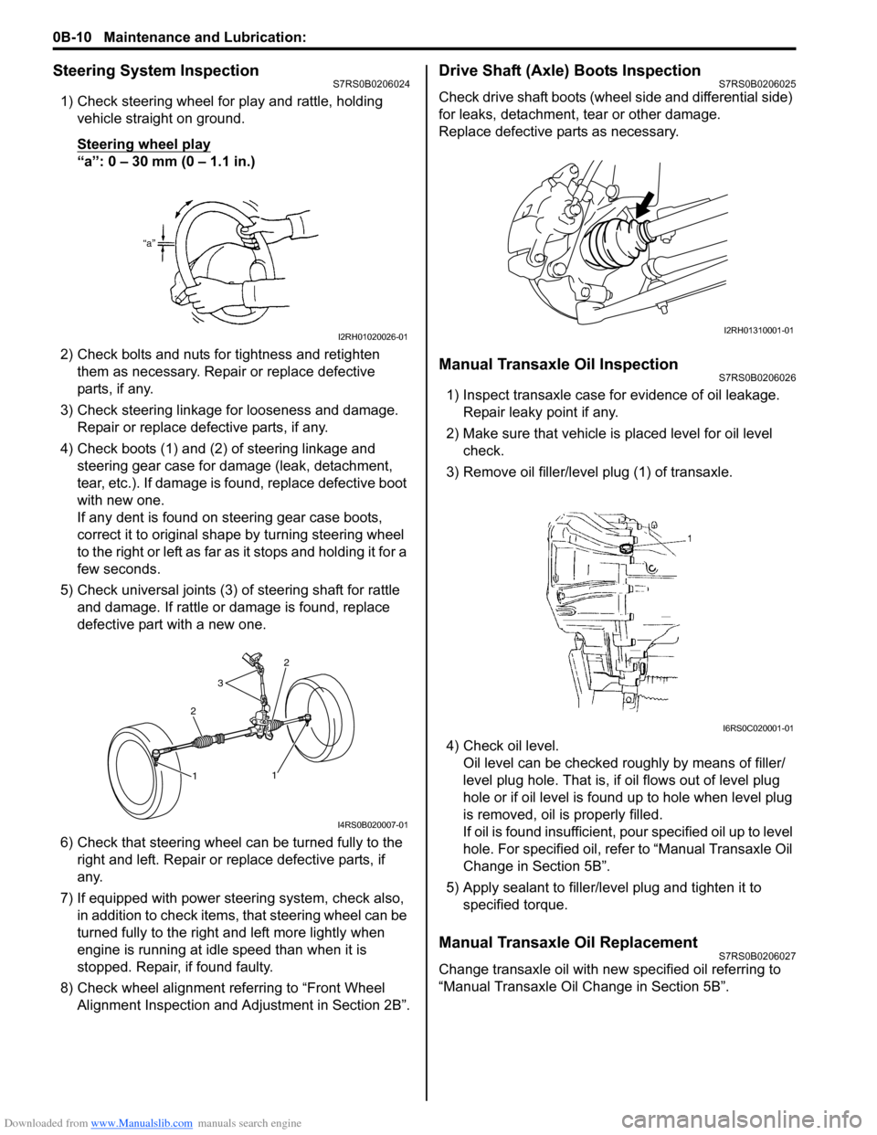
1) Check steering wheel for play and rattle, holding vehicle straight on ground.
Steering wheel play
“a”: 0 – 30 mm (0 – 1.1 in.)
2) Check bolts and nuts for tightness and retighten them as necessary. Repair or replace defective
parts, if any.
3) Check steering linkage for looseness and damage. Repair or replace defective parts, if any.
4) Check boots (1) and (2) of steering linkage and steering gear case for damage (leak, detachment,
tear, etc.). If damage is fo und, replace defective boot
with new one.
If any dent is found on steering gear case boots,
correct it to original shape by turning steering wheel
to the right or left as far as it stops and holding it for a
few seconds.
5) Check universal joints (3) of steering shaft for rattle and damage. If rattle or damage is found, replace
defective part with a new one.
6) Check that steering wheel can be turned fully to the
right and left. Repair or replace defective parts, if
any.
7) If equipped with power steering system, check also, in addition to check items, that steering wheel can be
turned fully to the right and left more lightly when
engine is running at idle speed than when it is
stopped. Repair, if found faulty.
8) Check wheel alignment referring to “Front Wheel Alignment Inspection and Adjustment in Section 2B”.
Drive Shaft (Axle) Boots InspectionS7RS0B0206025
Check drive shaft boots (wheel side and differential side)
for leaks, detachment, tear or other damage.
Replace defective parts as necessary.
Manual Transaxle Oil InspectionS7RS0B0206026
1) Inspect transaxle case for evidence of oil leakage. Repair leaky point if any.
2) Make sure that vehicle is placed level for oil level
check.
3) Remove oil filler/leve l plug (1) of transaxle.
4) Check oil level. Oil level can be checked roughly by means of filler/
level plug hole. That is, if oil flows out of level plug
hole or if oil level is found up to hole when level plug
is removed, oil is properly filled.
If oil is found insufficient, po ur specified oil up to level
hole. For specified oil, refe r to “Manual Transaxle Oil
Change in Section 5B”.
5) Apply sealant to filler/leve l plug and tighten it to
specified torque.
Manual Transaxle Oil ReplacementS7RS0B0206027
Change transaxle oil with new specified oil referring to
“Manual Transaxle Oil Change in Section 5B”.
I2RH01020026-01
2
3
2
1
1
I4RS0B020007-01
I2RH01310001-01
I6RS0C020001-01