engine size SUZUKI SWIFT 2007 2.G Service Workshop Manual
[x] Cancel search | Manufacturer: SUZUKI, Model Year: 2007, Model line: SWIFT, Model: SUZUKI SWIFT 2007 2.GPages: 1496, PDF Size: 34.44 MB
Page 2 of 1496
Downloaded from www.Manualslib.com manuals search engine IMPORTANT
WARNING/CAUTION/NOTE
Please read this manual and follow its instructions carefully. To emphasize special information, the words , and NOTE have special meanings. Pay specia l attention to the messages high-
lighted by these signal words.
The circle with a slash in this manual me ans “Don’t do this” or “Don’t let this happen”.
WARNING!CAUTION!
Indicates a potential hazard that could result in death or injury.
WARNING!
Indicates a potential hazard that could result in vehicle damage.
CAUTION!
NOTE:
Indicates special information to make main tenance easier or instructions clearer.
This service manual is intended for authorized Su zuki dealers and qualified service technicians only.
Inexperienced technicians or technicians without the proper tools and equipment may not be able to
properly perform the services described in this manual.
Improper repair may result in injury to the technician and may render the vehicle unsafe for the driver
and passengers.
WARNING!
For vehicles equipped with a Supplemental Restraint (Air Bag) System:
• Service on and around the air bag system components or wiring must be performed only by an authorized SUZUKI dealer. Refer to “Air Bag System Components and Wiring Location View” under
“General Description” in air bag system section in order to confirm whether you are performing ser-
vice on or near the air bag system components or wiring. Please observe all WARNINGS and “Ser-
vice Precautions” under “On-Vehicl e Service” in air bag system section before performing service
on or around the air bag system components or wiring. Failure to follow WARNINGS could result in
unintentional activation of the system or could re nder the system inoperative. Either of these two
conditions may result in severe injury.
If the air bag system and another vehicle system both need repair, Suzuki recommends that the air
bag system be repaired first, to help av oid unintended air bag system activation.
Do not modify the steering wheel, instrument pa nel or any other air bag system component on or
around air bag system components or wiring. Modi fications can adversely affect air bag system
performance and lead to injury.
If the vehicle will be exposed to temperatures over 93 °C (200 °F), for example, during a paint baking
process, remove the air bag system components, th at is air bag (inflator) modules, SDM and/or seat
belt with pretensioner, beforehand to avoid component damage or unintended activation.
WARNING!
Page 15 of 1496
Downloaded from www.Manualslib.com manuals search engine Precautions: 00-10
Air Bag WarningS7RS0B0000009
WARNING!
For vehicles equipped with Supplemental
Restraint (Air Bag) System:
• Service on and around the air bag system components or wiring must be performed
only by an authorized SUZUKI dealer. Refer
to “Air Bag System Components, Wiring
and Connectors Location in Section 8B” in
order to confirm whether you are
performing service on or near the air bag
system components or wiring. Please
observe all WARNINGS in Air Bag System
section and “Precautions on Service and
Diagnosis of Air Bag System in Section
8B” before performing service on or
around the air bag system components or
wiring. Failure to follow WARNINGS could
result in unintentional activation of the
system or could render the system
inoperative. Either of these two conditions
may result in severe injury.
• Technical service work must be started at least 90 seconds after the ignition switch is
turned to the LOCK position and the
negative cable is disconnected from the
battery. Otherwise, the system may be
activated by reserve energy in the Sensing
and Diagnostic Module (SDM).
Air Bag System Service WarningS7RS0B0000010
WARNING!
• Service on or around the air bag system components or wiring must be performed
only by an authorized SUZUKI dealer.
Please observe all WARNINGS in Air Bag
System section and “Precautions on
Service and Diagnosis of Air Bag System
in Section 8B” before performing service
on or around the air bag system
components or wiring. Failure to follow
WARNINGS could result in unintended
activation of the system or could render
the system inoperative. Either of these two
conditions may result in severe injury.
• The procedures in the air bag system section must be followed in the order
listed to disable the air bag system
temporarily and prevent false DTCs from
setting. Failure to follow procedures could
result in possible activation of the air bag
system, personal injury or otherwise
unneeded air bag system repairs.
Fastener CautionS7RS0B0000011
CAUTION!
When fasteners are removed, always reinstall
them at the same location from which they
were removed. If a fastener needs to be
replaced, use the correct part number
fastener for that application. If the correct
part number fastener is not available, a
fastener of equal size and strength (or
stronger) may be used. Fasteners that are not
reused, and those requiring thread-locking
compound, will be called out. The correct
torque value must be used when installing
fasteners that require it. If the conditions are
not followed, parts or system damage could
result.
Suspension CautionS7RS0B0000012
CAUTION!
• All suspension fasteners are an important attaching part in that it could affect the
performance of vital parts and systems,
and/or could result in major repair
expense. They must be replaced with one
of the same part number or with an
equivalent part if replacement becomes
necessary. Do not use a replacement part
of lesser quality or substitute design.
Torque values must be used as specified
during reassembly to assure proper
retention of this part.
• Never attempt to heat, quench or straighten any suspension part. Replace it
with a new part or damage to the part may
result.
Wheels and Tires CautionS7RS0B0000013
CAUTION!
All wheel fasteners are important attaching
parts in that they could affect the
performance of vital parts and systems, and/
or could result in major repair expense. They
must be replaced with one of the same part
number or with an eq uivalent part if
replacement becomes necessary. Do not use
a replacement part of lesser quality or
substitute design. Torque values must be
used as specified during reassembly to
assure proper retention of all parts.
There is to be no welding as it may result in
extensive damage and weakening of the
metal.
Page 27 of 1496
Downloaded from www.Manualslib.com manuals search engine General Information: 0A-6
When Using Floor Jack
WARNING!
If the vehicle to be jacked up only at the front
or rear end, be sure to block the wheels on
ground in order to ensure safety.
After the vehicle is jacked up, be sure to
support it on stands. It is extremely
dangerous to do any work on the vehicle
raised on jack alone.
CAUTION!
• Never apply jack against rear suspension parts (i.e., stabilizer, etc.) or vehicle floor,
or it may get deformed.
• When jacking up the front end, be sure to use an air type floor jack with the following
specified height or a manual type floor jack
of the following size. Otherwise, the jack
may cause the bumper or vehicle body
panel a damage.
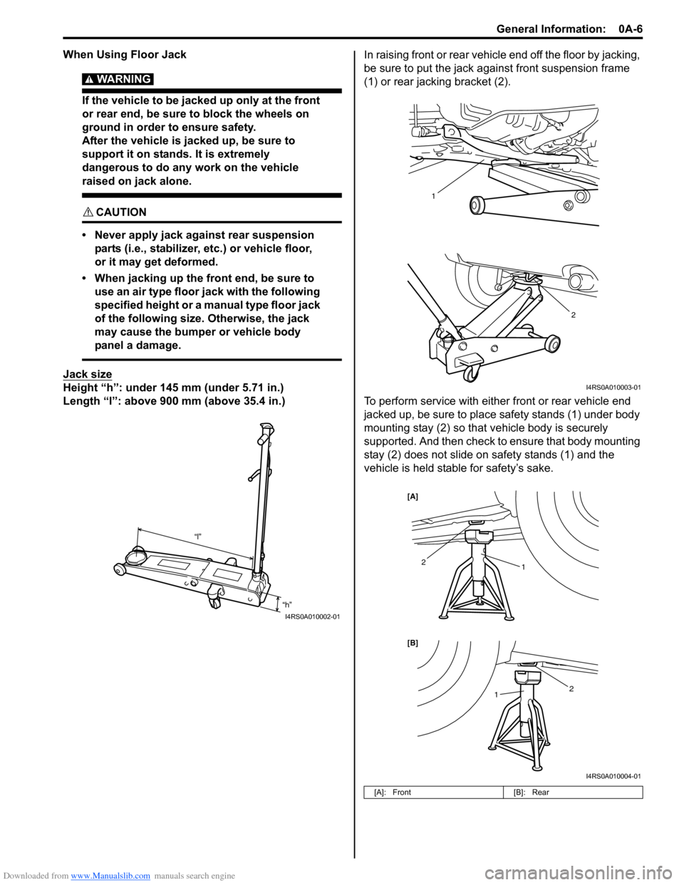
Jack size
Height “h”: under 145 mm (under 5.71 in.)
Length “l”: above 900 mm (above 35.4 in.) In raising front or rear vehicl
e end off the floor by jacking,
be sure to put the jack a gainst front suspension frame
(1) or rear jacking bracket (2).
To perform service with either front or rear vehicle end
jacked up, be sure to place safety stands (1) under body
mounting stay (2) so that vehicle body is securely
supported. And then check to ensure that body mounting
stay (2) does not slide on safety stands (1) and the
vehicle is held stable for safety’s sake.
“h”
“l”
I4RS0A010002-01
[A]: Front
[B]: Rear
2
1
I4RS0A010003-01
1
1
2
2
[B] [A]
I4RS0A010004-01
Page 322 of 1496
Downloaded from www.Manualslib.com manuals search engine 1D-37 Engine Mechanical:
Valves and Cylinder Head Disassembly and
Assembly
S7RS0B1406025
Disassembly1) For ease in servicing cylinder head, remove intake manifold, injectors, exhaust manifold from cylinder
head.
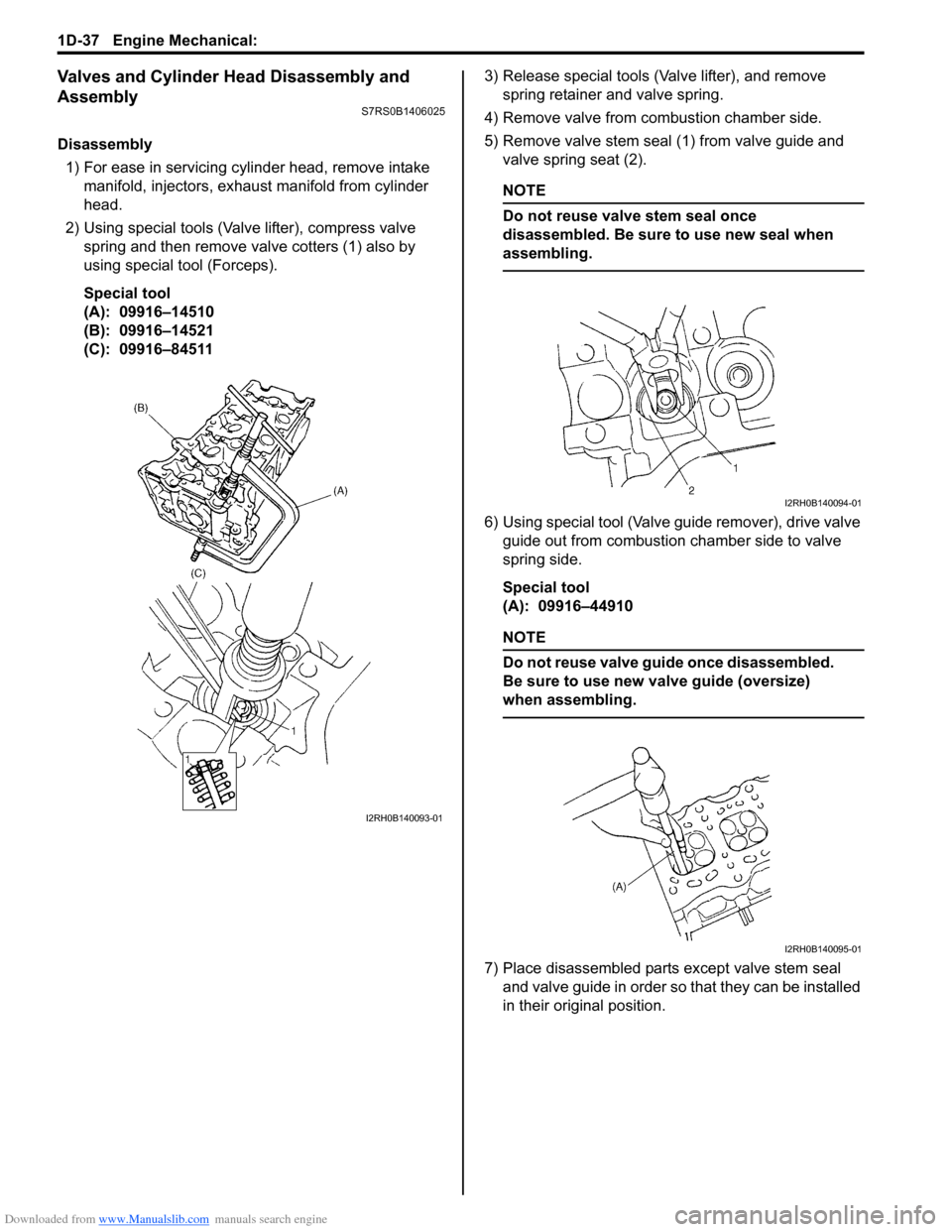
2) Using special tools (Val ve lifter), compress valve
spring and then remove valve cotters (1) also by
using special tool (Forceps).
Special tool
(A): 09916–14510
(B): 09916–14521
(C): 09916–84511 3) Release special tools (Valve lifter), and remove
spring retainer and valve spring.
4) Remove valve from combustion chamber side.
5) Remove valve stem seal (1) from valve guide and valve spring seat (2).
NOTE
Do not reuse valve stem seal once
disassembled. Be sure to use new seal when
assembling.
6) Using special tool (Valve guide remover), drive valve guide out from combustion chamber side to valve
spring side.
Special tool
(A): 09916–44910
NOTE
Do not reuse valve guide once disassembled.
Be sure to use new va lve guide (oversize)
when assembling.
7) Place disassembled parts except valve stem seal
and valve guide in order so that they can be installed
in their original position.
I2RH0B140093-01
I2RH0B140094-01
I2RH0B140095-01
Page 323 of 1496
Downloaded from www.Manualslib.com manuals search engine Engine Mechanical: 1D-38
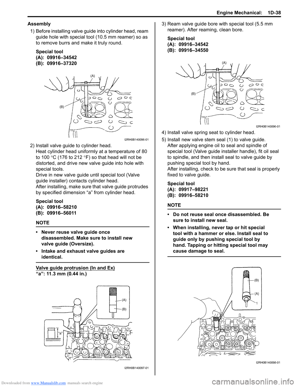
Assembly1) Before installing valve guide into cylinder head, ream
guide hole with special tool (10.5 mm reamer) so as
to remove burrs and make it truly round.
Special tool
(A): 09916–34542
(B): 09916–37320
2) Install valve guide to cylinder head. Heat cylinder head uniformly at a temperature of 80
to 100 °C (176 to 212 °F) so that head will not be
distorted, and drive new valve guide into hole with
special tools.
Drive in new valve guide until special tool (Valve
guide installer) contacts cylinder head.
After installing, ma ke sure that valve guide pr otrudes
by specified dimension “a” from cylinder head.
Special tool
(A): 09916–58210
(B): 09916–56011
NOTE
• Never reuse valve guide once disassembled. Make sure to install new
valve guide (Oversize).
• Intake and exhaust valve guides are identical.
Valve guide protrusion (In and Ex)
“a”: 11.3 mm (0.44 in.) 3) Ream valve guide bore with special tool (5.5 mm
reamer). After reaming, clean bore.
Special tool
(A): 09916–34542
(B): 09916–34550
4) Install valve spring seat to cylinder head.
5) Install new valve stem seal (1) to valve guide. After applying engine oil to seal and spindle of
special tool (Valve guide installer handle), fit oil seal
to spindle, and then install seal to valve guide by
pushing special tool by hand.
After installing, check to be sure that seal is properly
fixed to valve guide.
Special tool
(A): 09917–98221
(B): 09916–58210
NOTE
• Do not reuse seal once disassembled. Be sure to install new seal.
• When installing, never tap or hit special tool with a hammer or else. Install seal to
guide only by pushing special tool by
hand. Tapping or hitting special tool may
cause damage to seal.
I2RH0B140096-01
I2RH0B140097-01
I2RH0B140096-01
I2RH0B140098-01
Page 326 of 1496
Downloaded from www.Manualslib.com manuals search engine 1D-41 Engine Mechanical:
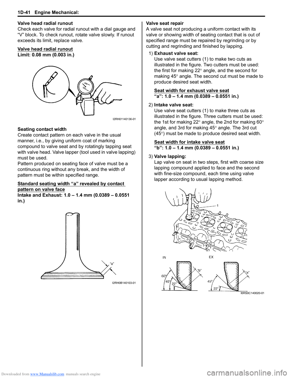
Valve head radial runout
Check each valve for radial runout with a dial gauge and
“V” block. To check runout, rotate valve slowly. If runout
exceeds its limit, replace valve.
Valve head radial runout
Limit: 0.08 mm (0.003 in.)
Seating contact width
Create contact pattern on each valve in the usual
manner, i.e., by giving uniform coat of marking
compound to valve seat and by rotatingly tapping seat
with valve head. Valve lapper (tool used in valve lapping)
must be used.
Pattern produced on seating face of valve must be a
continuous ring without any break, and the width of
pattern must be within specified range.
Standard seating width “a” revealed by contact
pattern on valve face
Intake and Exhaust: 1.0 – 1.4 mm (0.0389 – 0.0551
in.)Valve seat repair
A valve seat not producing
a uniform contact with its
valve or showing width of seating contact that is out of
specified range must be repaired by regrinding or by
cutting and regrinding and finished by lapping.
1) Exhaust valve seat:
Use valve seat cutters (1 ) to make two cuts as
illustrated in the figure. Two cutters must be used:
the first for making 22 ° angle, and the second for
making 45 ° angle. The second cut must be made to
produce desired seat width.
Seat width for exhaust valve seat
“a”: 1.0 – 1.4 mm (0.0389 – 0.0551 in.)
2) Intake valve seat:
Use valve seat cutters (1) to make three cuts as
illustrated in the figure. Th ree cutters must be used:
the 1st for making 22 ° angle, the 2nd for making 60 °
angle, and 3rd for making 45 ° angle. The 3rd cut
(45 °) must be made to produce desired seat width.
Seat width for intake valve seat
“b”: 1.0 – 1.4 mm (0.0389 – 0.0551 in.)
3) Valve lapping:
Lap valve on seat in two steps, first with coarse size
lapping compound applied to face and the second
with fine-size compound, each time using valve
lapper according to usual lapping method.
I2RH01140136-01
I2RH0B140103-01
I6RS0C140020-01
Page 332 of 1496
Downloaded from www.Manualslib.com manuals search engine 1D-47 Engine Mechanical:
Cylinders, Pistons and Piston Rings InspectionS7RS0B1406032
Cylinder
Visual inspection
Inspect cylinder walls for scratches, roughness or ridges
which indicate excessive wear. If cylinder bore is very
rough or deeply scratched, or ridged, rebore cylinder and
use over size piston.
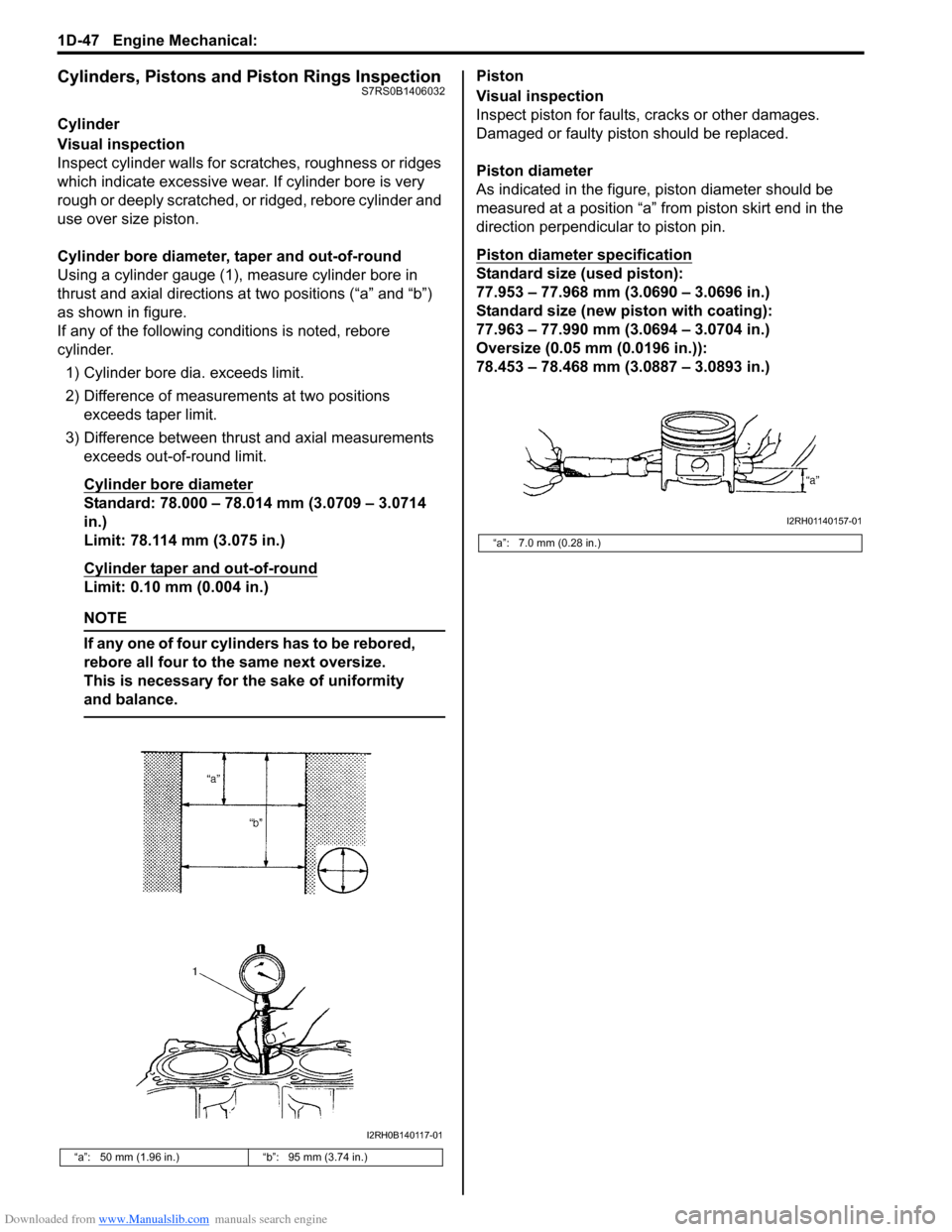
Cylinder bore diameter, taper and out-of-round
Using a cylinder gauge (1), measure cylinder bore in
thrust and axial directions at two positions (“a” and “b”)
as shown in figure.
If any of the following conditions is noted, rebore
cylinder.1) Cylinder bore dia. exceeds limit.
2) Difference of measurements at two positions exceeds taper limit.
3) Difference between thrust and axial measurements exceeds out-of-round limit.
Cylinder bore diameter
Standard: 78.000 – 78.014 mm (3.0709 – 3.0714
in.)
Limit: 78.114 mm (3.075 in.)
Cylinder taper and out-of-round
Limit: 0.10 mm (0.004 in.)
NOTE
If any one of four cylinders has to be rebored,
rebore all four to the same next oversize.
This is necessary for the sake of uniformity
and balance.
Piston
Visual inspection
Inspect piston for faults, cracks or other damages.
Damaged or faulty piston should be replaced.
Piston diameter
As indicated in the figure, piston diameter should be
measured at a position “a” from piston skirt end in the
direction perpendicular to piston pin.
Piston diameter specification
Standard size (used piston):
77.953 – 77.968 mm (3.0690 – 3.0696 in.)
Standard size (new piston with coating):
77.963 – 77.990 mm (3.0694 – 3.0704 in.)
Oversize (0.05 mm (0.0196 in.)):
78.453 – 78.468 mm (3.0887 – 3.0893 in.)
“a”: 50 mm (1.96 in.) “b”: 95 mm (3.74 in.)
I2RH0B140117-01
“a”: 7.0 mm (0.28 in.)
I2RH01140157-01
Page 333 of 1496
Downloaded from www.Manualslib.com manuals search engine Engine Mechanical: 1D-48
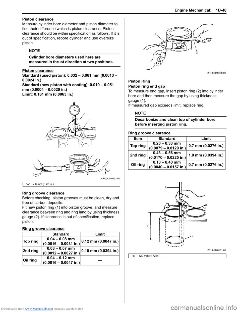
Piston clearance
Measure cylinder bore diameter and piston diameter to
find their difference which is piston clearance. Piston
clearance should be within spec ification as follows. If it is
out of specification, rebore cylinder and use oversize
piston.
NOTE
Cylinder bore diameters used here are
measured in thrust direction at two positions.
Piston clearance
Standard (used piston): 0.032 – 0.061 mm (0.0013 –
0.0024 in.)
Standard (new piston with coating): 0.010 – 0.051
mm (0.0004 – 0.0020 in.)
Limit: 0.161 mm (0.0063 in.)
Ring groove clearance
Before checking, piston grooves must be clean, dry and
free of carbon deposits.
Fit new piston ring (1) into piston groove, and measure
clearance between ring and ring land by using thickness
gauge (2). If clearance is ou t of specification, replace
piston.
Ring groove clearance
Piston Ring
Piston ring end gap
To measure end gap, insert piston ring (2) into cylinder
bore and then measure the gap by using thickness
gauge (1).
If measured gap exceeds limit, replace ring.
NOTE
Decarbonize and clean top of cylinder bore
before inserting piston ring.
Ring groove clearance
“a”: 7.0 mm (0.28 in.)
Standard Limit
Top ring 0.04 – 0.08 mm
(0.0016 – 0.0031 in.) 0.12 mm (0.0047 in.)
2nd ring 0.03 – 0.07 mm
(0.0012 – 0.0027 in.) 0.10 mm (0.0394 in.)
Oil ring 0.04 – 0.12 mm
(0.0016 – 0.0047 in.) —
I4RS0A140022-01
Item Standard
Limit
To p r i n g 0.20 – 0.33 mm
(0.0079 – 0.0129 in.) 0.7 mm (0.0276 in.)
2nd ring 0.43 – 0.56 mm
(0.0170 – 0.0220 in.) 1.0 mm (0.0394 in.)
Oil ring 0.10 – 0.40 mm
(0.0040 – 0.0157 in.) 0.7 mm (0.0276 in.)
“a”: 120 mm (4.72 in.)
I2RH01140159-01
I2RH01140161-01
Page 335 of 1496
Downloaded from www.Manualslib.com manuals search engine Engine Mechanical: 1D-50
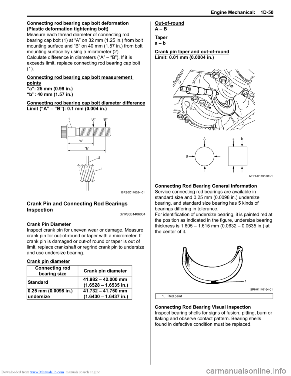
Connecting rod bearing cap bolt deformation
(Plastic deformation tightening bolt)
Measure each thread diameter of connecting rod
bearing cap bolt (1) at “A” on 32 mm (1.25 in.) from bolt
mounting surface and “B” on 40 mm (1.57 in.) from bolt
mounting surface by using a micrometer (2).
Calculate difference in diameters (“A” – “B”). If it is
exceeds limit, replace connecting rod bearing cap bolt
(1).
Connecting rod bearing cap bolt measurement
points
“a”: 25 mm (0.98 in.)
“b”: 40 mm (1.57 in.)
Connecting rod bearing cap bolt diameter difference
Limit (“A” – “B”): 0.1 mm (0.004 in.)
Crank Pin and Connecting Rod Bearings
Inspection
S7RS0B1406034
Crank Pin Diameter
Inspect crank pin for uneven wear or damage. Measure
crank pin for out-of-round or taper with a micrometer. If
crank pin is damaged or out-of round or taper is out of
limit, replace crankshaft or regrind crank pin to undersize
and use undersize bearing.
Crank pin diameter
Out-of-round
A – B
Ta p e r
a – b
Crank pin taper and out-of-round
Limit: 0.01 mm (0.0004 in.)
Connecting Rod Bearing General Information
Service connecting rod be arings are available in
standard size and 0.25 mm (0.0098 in.) undersize
bearing, and standard size bearing has 5 kinds of
bearings differing in tolerance.
For identification of undersize bearing, it is painted red at
the position as indicated in the figure, undersize bearing
thickness is 1.605 – 1.615 mm (0.0632 – 0.0635 in.) at
the center of it.
Connecting Rod Bearing Visual Inspection
Inspect bearing shells for signs of fusion, pitting, burn or
flaking and observe contact pattern. Bearing shells
found in defective condition must be replaced.
Connecting rod
bearing size Crank pin diameter
Standard 41.982 – 42.000 mm
(1.6528 – 1.6535 in.)
0.25 mm (0.0098 in.)
undersize 41.732 – 41.750 mm
(1.6430 – 1.6437 in.)
I6RS0C140024-01
1. Red paint
I2RH0B140120-01
I2RH01140164-01
Page 336 of 1496
Downloaded from www.Manualslib.com manuals search engine 1D-51 Engine Mechanical:
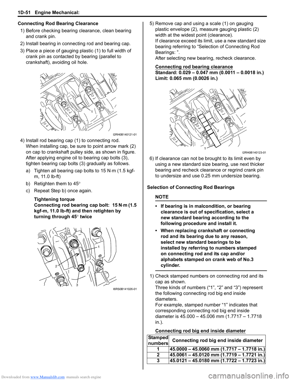
Connecting Rod Bearing Clearance1) Before checking bearing clearance, clean bearing and crank pin.
2) Install bearing in connecting rod and bearing cap.
3) Place a piece of gauging plastic (1) to full width of crank pin as contacted by bearing (parallel to
crankshaft), avoiding oil hole.
4) Install rod bearing cap (1) to connecting rod. When installing cap, be sure to point arrow mark (2)
on cap to crankshaft pulley side, as shown in figure.
After applying engine oil to bearing cap bolts (3),
tighten bearing cap bolts (3) gradually as follows.
a) Tighten all bearing cap bolts to 15 N ⋅m (1.5 kgf-
m, 11.0 lb-ft)
b) Retighten them to 45°
c) Repeat Step b) once again.
Tightening torque
Connecting rod bearing cap bolt: 15 N ⋅m (1.5
kgf-m, 11.0 lb-ft) and then retighten by
turning through 45 ° twice 5) Remove cap and using a scale (1) on gauging
plastic envelope (2), measure gauging plastic (2)
width at the widest point (clearance).
If clearance exceed its limit, use a new standard size
bearing referring to “Selection of Connecting Rod
Bearings: ”.
After selecting new bearing, recheck clearance.
Connecting rod bearing clearance
Standard: 0.029 – 0.047 mm (0.0011 – 0.0018 in.)
Limit: 0.065 mm (0.0026 in.)
6) If clearance can not be brought to its limit even by using a new standard size bearing, use next thicker
bearing and recheck clearance or regrind crank pin
to undersize and use 0.25 mm undersize bearing.
Selection of Connecting Rod Bearings
NOTE
• If bearing is in malcondition, or bearing clearance is out of specification, select a
new standard bearing according to the
following procedure and install it.
• When replacing crankshaft or connecting rod and its bearing due to any reason,
select new standard bearings to be
installed by referring to numbers stamped
on connecting rod and its cap and/or
alphabets stamped on crank web of No.3
cylinder.
1) Check stamped numbers on connecting rod and its cap as shown.
Three kinds of numbers (“1”, “2” and “3”) represent
the following connecting rod big end inside
diameters.
For example, stamped number “1” indicates that
corresponding connecting rod big end inside
diameter is 45.000 – 45.006 mm (1.7717 – 1.7718
in.).
Connecting rod big end inside diameter
I2RH0B140121-01
I6RS0B141026-01
Stamped
numbers Connecting rod big end inside diameter
1 45.0000 – 45.0060 mm (1.7717 – 1.7718 in.)
2 45.0061 – 45.0120 mm (1.7719 – 1.7721 in.)
3 45.0121 – 45.0180 mm (1.7722 – 1.7723 in.)
I2RH0B140123-01