oil pan SUZUKI SWIFT 2007 2.G Service Workshop Manual
[x] Cancel search | Manufacturer: SUZUKI, Model Year: 2007, Model line: SWIFT, Model: SUZUKI SWIFT 2007 2.GPages: 1496, PDF Size: 34.44 MB
Page 6 of 1496
Downloaded from www.Manualslib.com manuals search engine 00-1 Precautions:
Precautions
Precautions
Precautions
Precautions for Vehicles Equipped with a
Supplemental Restraint (Air Bag) System
S7RS0B0000001
WARNING!
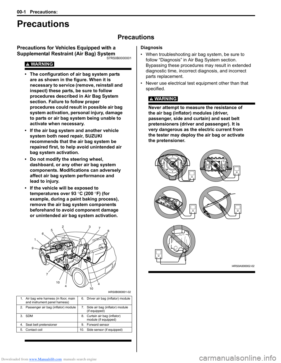
• The configuration of air bag system parts are as shown in the figure. When it is
necessary to service (remove, reinstall and
inspect) these parts, be sure to follow
procedures described in Air Bag System
section. Failure to follow proper
procedures could result in possible air bag
system activation, personal injury, damage
to parts or air bag system being unable to
activate when necessary.
• If the air bag system and another vehicle system both need repair, SUZUKI
recommends that the air bag system be
repaired first, to help avoid unintended air
bag system activation.
• Do not modify the steering wheel, dashboard, or any other air bag system
components. Modifications can adversely
affect air bag system performance and
lead to injury.
• If the vehicle will be exposed to temperatures over 93 °C (200 °F) (for
example, during a paint baking process),
remove the air bag system components
beforehand to avoid component damage
or unintended air bag system activation.
Diagnosis
• When troubleshooting air bag system, be sure to follow “Diagnosis” in Air Bag System section.
Bypassing these procedures may result in extended
diagnostic time, incorrect diagnosis, and incorrect
parts replacement.
• Never use electrical test equipment other than that specified.
WARNING!
Never attempt to measure the resistance of
the air bag (inflator) modules (driver,
passenger, side and curtain) and seat belt
pretensioners (driver and passenger). It is
very dangerous as the electric current from
the tester may deploy the air bag or activate
the pretensioner.
1. Air bag wire harness (in floor, main and instrument panel harness) 6. Driver air bag (inflator) module
2. Passenger air bag (inflator) module 7. Side air bag (inflator) module (if equipped)
3. SDM 8. Curtain air bag (inflator) module (if equipped)
4. Seat belt pretensioner 9. Forward sensor
5. Contact coil 10. Side sensor (if equipped)
1 2
3
4
4
5
6
7 7
8
9
10 10
I4RS0B000001-02
I4RS0A000002-02
Page 8 of 1496
Downloaded from www.Manualslib.com manuals search engine 00-3 Precautions:
WARNING!
SDM
• For handling and storage of a SDM, select a place where the ambient temperature
below 65 °C (150 °F), without high humidity
and away from electric noise.
• During service procedures, be very careful when handling a Sensing and Diagnostic
Module (SDM). Never strike or jar the SDM.
• Never power up the air bag system when the SDM is not rigidly attached to the
vehicle. All SDM and mounting bracket
fasteners must be carefully torqued and
the arrow must be pointing toward the
front of the vehicle to ensure proper
operation of the air bag system.
The SDM could be activated when powered
while not rigidly att ached to the vehicle
which could cause deployment and result
in personal injury.
WARNING!
Driver and Passenger Seat Belt
Pretensioners
• For handling and storage of a live seat belt pretensioner, select a place where the
ambient temperature below 65 °C (150 ° F),
without high humidity and away from
electric noise.
• Never carry seat belt pretensioner by wire or connector of pretensioner. When
placing a live seat belt pretensioner on the
workbench or some place like that, never
put something on seat belt pretensioner.
Otherwise, personal injury may result.
• Never dispose of live (inactivated) seat belt pretensioners (drive and passenger). If
disposal is necessary, be sure to activate
them according to activation procedures
described in “Air Bag (Inflator) Module and
Seat Belt Pretensioner Disposal in Section
8B” before disposal.
• The seat belt pretensioner immediately after activation is very hot. Wait for at least
half an hour to cool it off before
proceeding the work.
• With many service procedures, gloves and safety glasses should be worn to prevent
any possible irritation of the skin or eyes.
• Even when the accident was light enough not to cause air bags to activate, be sure to inspect system
parts and other related parts according to instructions
under “Repair and Inspection Required after Accident
in Section 8B”.
• When servicing parts other than air bag system, if shocks may be applied to air bag system component
parts, remove those parts beforehand.
• When handling the air bag (inflator) modules (driver, passenger, side and curtain), seat belt pretensioners
(driver and passenger), forward sensor, side sensors
or SDM, be careful not to drop it or apply an impact to
it. If an excessive impact was applied, never attempt
disassembly or repair but replace it with a new one.
• When grease, cleaning agent, oil, water, etc. has got onto air bag (inflator) modules (driver, passenger, side
and curtain) or seat belt pretensioners (drive and
passenger), wipe off immediately with a dry cloth.
• Air bag wire harness is included in floor and instrument panel wire harnesses. Air bag wire
harness branched off from floor and instrument panel
wire harnesses can be identifie d easily as it is covered
with a yellow protection tube and it has yellow
connectors. Be very ca reful when handling it.
• When an open in air bag wire harness, damaged wire harness, connector or terminal is found, replace wire
harness, connectors and terminals as an assembly.
• Do not apply power to the air bag system unless all components are connected or a diagnostic flow
requests it, as this will set a DTC.
• Never use air bag system component parts from another vehicle.
• When using electric welding, be sure to disconnect all air bag (inflator) module connectors and pretensioner
connectors from air bag wire harness respectively.
• Never expose air bag system component parts directly to hot air (drying or baking the vehicle after
painting) or flames.
• WARNING / CAUTION labels are attached on each
part of air bag system components. Be sure to follow
the instructions.
• After vehicle is completely repaired, perform “Air Bag Diagnostic System Check in Section 8B”.
Page 35 of 1496
Downloaded from www.Manualslib.com manuals search engine Maintenance and Lubrication: 0B-5
4) Screw new filter on oil filter stand by hand until the filter O-ring contacts mounting surface.
CAUTION!
To tighten oil filter prop erly, it is important to
accurately identify the position at which filter
O-ring first contacts mounting surface.
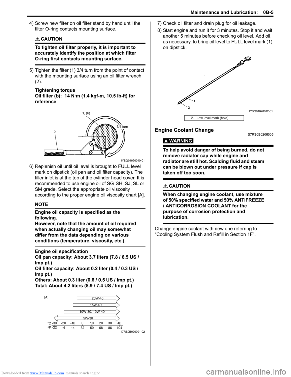
5) Tighten the filter (1) 3/4 tu rn from the point of contact
with the mounting surface using an oil filter wrench
(2).
Tightening torque
Oil filter (b): 14 N·m (1 .4 kgf-m, 10.5 lb-ft) for
reference
6) Replenish oil until oil leve l is brought to FULL level
mark on dipstick (oil pan and oil filter capacity). The
filler inlet is at the top of the cylinder head cover. It is
recommended to use engine oil of SG, SH, SJ, SL or
SM grade. Select the appropriate oil viscosity
according to the proper engine oil viscosity chart [A].
NOTE
Engine oil capacity is specified as the
following.
However, note that the amount of oil required
when actually changing oil may somewhat
differ from the data depending on various
conditions (temperature, viscosity, etc.).
Engine oil specification
Oil pan capacity: About 3.7 liters (7.8 / 6.5 US /
lmp pt.)
Oil filter capacity: About 0.2 liter (0.4 / 0.3 US /
lmp pt.)
Others: About 0.3 liter (0 .6 / 0.5 US / lmp pt.)
Total: About 4.2 liters (8.9 / 7.4 US / lmp pt.) 7) Check oil filter and drain plug for oil leakage.
8) Start engine and run it for 3 minutes. Stop it and wait
another 5 minutes before checking oil level. Add oil,
as necessary, to bring oil le vel to FULL level mark (1)
on dipstick.
Engine Coolant ChangeS7RS0B0206005
WARNING!
To help avoid danger of being burned, do not
remove radiator cap while engine and
radiator are still hot. Scalding fluid and steam
can be blown out under pressure if cap is
taken off too soon.
CAUTION!
When changing engine coolant, use mixture
of 50% specified water and 50% ANTIFREEZE
/ ANTICORROSION COOLANT for the
purpose of corrosion protection and
lubrication.
Change engine coolant with new one referring to
“Cooling System Flush and Refill in Section 1F”.
IYSQ01020010-01
Co
Fo-30
-22 -20
-4 -10
14 32 50 68 86 104 010203040
5W-30
20W-40
15W-40
10W-30, 10W-40
[A]
I7RS0B020001-02
2. Low level mark (hole)
IYSQ01020012-01
Page 48 of 1496

Downloaded from www.Manualslib.com manuals search engine 1-iv Table of Contents
Engine Lubrication System.....................1E-1
General Description ............................................. 1E-1
Engine Lubrication Description ........................... 1E-1
Diagnostic Information and Procedures ............ 1E-2 Oil Pressure Check ............................................. 1E-2
Repair Instructions ........... ................................... 1E-3
Heat Exchanger Components ............................. 1E-3
Heat Exchanger On-Vehicle Inspection .............. 1E-4
Heat Exchanger Removal and Installation .......... 1E-4
Oil Pan and Oil Pump Strainer Components....... 1E-5
Oil Pan and Oil Pump Strainer Removal and
Installation ......................................................... 1E-5
Oil Pan and Oil Pump Stra iner Cleaning ............. 1E-7
Oil Pump Components ........................................ 1E-8
Oil Pump Removal and Installation ..................... 1E-8
Oil Pump Disassembly and Reassembly ............ 1E-8
Oil Pump Inspection ............................................ 1E-9
Specifications .... ................................................. 1E-11
Tightening Torque Specifications ...................... 1E-11
Special Tools and Equipmen t ........................... 1E-11
Recommended Service Material ....................... 1E-11
Special Tool ...................................................... 1E-11
Engine Cooling System ..... ...................... 1F-1
General Description .......... ................................... 1F-1
Cooling System Descriptio n ................................ 1F-1
Coolant Description ............................................. 1F-1
Schematic and Routing Diagram ........................ 1F-2 Coolant Circulation .............................................. 1F-2
Diagnostic Information and Procedures ............ 1F-4 Engine Cooling Symptom Diagnosis ................... 1F-4
Repair Instructions ........... ................................... 1F-5
Cooling System Components.............................. 1F-5
Coolant Level Check ........................................... 1F-6
Engine Cooling System Inspection and Cleaning ............................................................ 1F-6
Cooling System Draining.. ................................... 1F-6
Cooling System Flush and Refill ......................... 1F-7
Cooling Water Pipes or Hoses Removal and Installation ......................................................... 1F-7
Thermostat Removal and In stallation.................. 1F-8
Thermostat Inspection......................................... 1F-8
Radiator Cooling Fan Motor On-Vehicle Inspection .......................................................... 1F-9
Radiator Cooling Fan Rela y Inspection............... 1F-9
Radiator Cooling Fan Removal and Installation ....................................................... 1F-10
Radiator On-Vehicle Inspection and Cleaning .. 1F-10
Radiator Removal and Inst allation .................... 1F-10
Water Pump Removal and In stallation .............. 1F-11
Water Pump Inspection ..................................... 1F-11
Specifications .... ................................................. 1F-12
Tightening Torque Specifications ...................... 1F-12
Special Tools and Equipmen t ........................... 1F-12
Recommended Service Material ....................... 1F-12
Fuel System ................... .......................... 1G-1
Precautions.......................................................... 1G-1 Precautions on Fuel System Service ................. 1G-1
General Description ............................................ 1G-1 Fuel System Description .................................... 1G-1
Fuel Delivery System Description ...................... 1G-1
Fuel Pump Description ....................................... 1G-2
Schematic and Routing Diagram ....................... 1G-2 Fuel Delivery System Diag ram........................... 1G-2
Diagnostic Information and Procedures ........... 1G-2 Fuel Pressure Inspection ................................... 1G-2
Fuel Cut Operation Inspection ........................... 1G-3
Repair Instructions ............ ................................. 1G-4
Fuel System Components .................................. 1G-4
Fuel Hose Disconnecting and Reconnecting ..... 1G-5
Fuel Pressure Relief Procedure ......................... 1G-7
Fuel Leakage Check Procedure......................... 1G-7
Fuel Lines On-Vehicle Inspection ...................... 1G-7
Fuel Pipe Removal and Installation.................... 1G-7
Fuel Injector On-Vehicle Inspection ................... 1G-8
Fuel Injector Removal and Installation ............... 1G-8
Fuel Injector Inspection ...................................... 1G-9
Fuel Filler Cap Inspection . ............................... 1G-10
Fuel Tank Inlet Valve Removal and Installation ...................................................... 1G-11
Fuel Tank Inlet Valve Inspection ...................... 1G-12
Fuel Tank Removal and Installation ................. 1G-12
Fuel Tank Inspection ........................................ 1G-13
Fuel Tank Purging Procedure .......................... 1G-14
Fuel Pump On-Vehicle Inspection.................... 1G-14
Fuel Pump Assembly Removal and Installation ...................................................... 1G-14
Main Fuel Level Sensor Removal and Installation ...................................................... 1G-15
Fuel Pump Inspection ...................................... 1G-16
Specifications ..................... ............................... 1G-16
Tightening Torque Specifications ..................... 1G-16
Special Tools and Equipmen t .......................... 1G-17
Special Tool ..................................................... 1G-17
Ignition System .............. .......................... 1H-1
General Description .............................................1H-1
Ignition System Construction ..............................1H-1
Schematic and Routing Diagram ........................1H-2 Ignition System Wiring Circuit Diagram...............1H-2
Component Location ............ ...............................1H-3
Ignition System Components Location................1H-3
Diagnostic Information and Procedures ............1H-4 Ignition System Symptom Diagnosis...................1H-4
Reference Waveform of Ignition System.............1H-4
Ignition System Check ........................................1H-4
Ignition Spark Test ..............................................1H-6
Repair Instructions ............ ..................................1H-6
High-Tension Cord Removal and Installation......1H-6
High-Tension Cord Inspection.............................1H-7
Spark Plug Removal and Installation ..................1H-7
Spark Plug Inspection .........................................1H-7
Ignition Coil Assembly (Including ignitor)
Removal and Installation ...................................1H-8
Ignition Coil Assembly (Including ignitor)
Inspection ..........................................................1H-8
Page 51 of 1496
Downloaded from www.Manualslib.com manuals search engine Engine General Information and Diagnosis: 1A-1
Engine
Engine General Information and Diagnosis
Precautions
Precautions on Engine ServiceS7RS0B1100001
CAUTION!
The following information on engine service
should be noted carefully, as it is important in
preventing damage, and in contributing to
reliable engine performance.
• When raising or supporting engine for any reason, do
not use a jack under oil pan. Due to small clearance
between oil pan and oil pump strainer, jacking against
oil pan may cause it to be bent against strainer,
resulting in damaged oil pick-up unit.
• It should be kept in mind , while working on engine,
that 12-volt electrical syste m is capable of violent and
damaging short circuits.
When performing any work where electrical terminals
can be grounded, ground cable of the battery should
be disconnected at battery.
• Any time the air cleaner, throttle body or intake manifold is removed, the intake opening should be
covered. This will protect against accidental entrance
of foreign material which could follow intake passage
into cylinder and cause extensive damage when
engine is started.
Precaution on On-Board Diagnostic (OBD)
System
S7RS0B1100005
There are two types of On -Board Diagnostic (OBD)
system, Euro OBD system and non-Euro-OBD system,
depending on the vehicle specification.
As the diagnosis function is different between these two
types, be sure to fully understand the OBD system
referring to “On-Board Diagnostic System Description”.
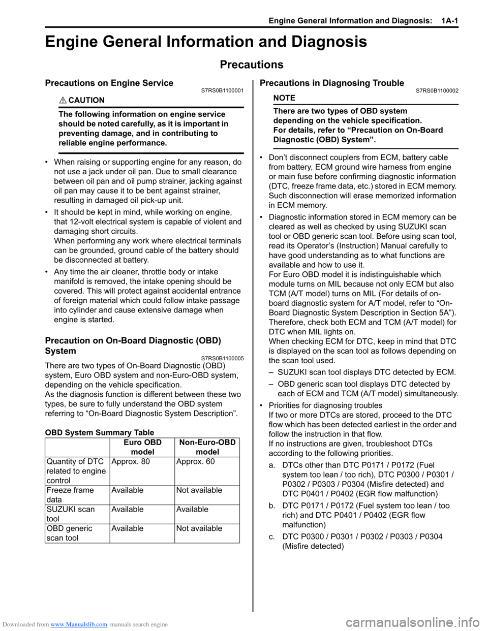
OBD System Summary Table
Precautions in Diagnosing TroubleS7RS0B1100002
NOTE
There are two types of OBD system
depending on the vehicle specification.
For details, refer to “Precaution on On-Board
Diagnostic (OBD) System”.
• Don’t disconnect couplers from ECM, battery cable
from battery, ECM ground wire harness from engine
or main fuse before confirming diagnostic information
(DTC, freeze frame data, etc.) stored in ECM memory.
Such disconnection will erase memorized information
in ECM memory.
• Diagnostic information stored in ECM memory can be cleared as well as checke d by using SUZUKI scan
tool or OBD generic scan tool. Before using scan tool,
read its Operator’s (Instruction) Manual carefully to
have good understanding as to what functions are
available and how to use it.
For Euro OBD model it is indistinguishable which
module turns on MIL because not only ECM but also
TCM (A/T model) turns on MIL (For details of on-
board diagnostic system for A/T model, refer to “On-
Board Diagnostic System Description in Section 5A”).
Therefore, check both ECM and TCM (A/T model) for
DTC when MIL lights on.
When checking ECM for DTC, keep in mind that DTC
is displayed on the scan tool as follows depending on
the scan tool used.
– SUZUKI scan tool displays DTC detected by ECM.
– OBD generic scan tool displays DTC detected by each of ECM and TCM (A/T model) simultaneously.
• Priorities for diagnosing troubles If two or more DTCs are stored, proceed to the DTC
flow which has been detected earliest in the order and
follow the instructi on in that flow.
If no instructions are given, troubleshoot DTCs
according to the following priorities.
a. DTCs other than DTC P0171 / P0172 (Fuel system too lean / too rich), DTC P0300 / P0301 /
P0302 / P0303 / P0304 (Misfire detected) and
DTC P0401 / P0402 (EGR flow malfunction)
b. DTC P0171 / P0172 (Fuel system too lean / too rich) and DTC P0401 / P0402 (EGR flow
malfunction)
c. DTC P0300 / P0301 / P0302 / P0303 / P0304 (Misfire detected)
Euro OBD
model Non-Euro-OBD
model
Quantity of DTC
related to engine
control Approx. 80 Approx. 60
Freeze frame
data Available Not available
SUZUKI scan
tool Available Available
OBD generic
scan tool Available Not available
Page 91 of 1496
Downloaded from www.Manualslib.com manuals search engine Engine General Information and Diagnosis: 1A-41
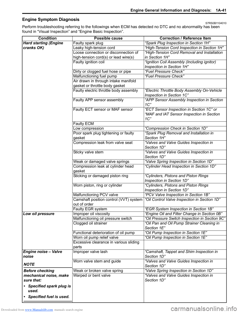
Engine Symptom DiagnosisS7RS0B1104010
Perform troubleshooting referring to the followings when ECM has detected no DTC and no abnormality has been
found in “Visual Inspection” and “Engine Basic Inspection”.
Condition Possible cause Correction / Reference Item
Hard starting (Engine
cranks OK) Faulty spark plug
“Spark Plug Inspection in Section 1H”
Leaky high-tension cord “High-Tension Cord Inspection in Section 1H”
Loose connection or disconnection of
high-tension cord(s) or lead wire(s) “High-Tension Cord Removal and Installation
in Section 1H”
Faulty ignition coil “Ignition Coil Assembly (Including ignitor)
Inspection in Section 1H”
Dirty or clogged fuel hose or pipe “Fuel Pressure Check”
Malfunctioning fuel pump “Fuel Pressure Check”
Air drawn in through intake manifold
gasket or throttle body gasket
Faulty electric throttle body assembly “Electric Throttle Body Assembly On-Vehicle
Inspection in Section 1C”
Faulty APP sensor assembly “APP Sensor Assembly Inspection in Section
1C”
Faulty ECT sensor or MAF sensor “ECT Sensor Inspection in Section 1C” or
“MAF and IAT Sensor Inspection in Section
1C”
Faulty ECM
Low compression “Compression Check in Section 1D”
Poor spark plug tightening or faulty
gasket “Spark Plug Removal and Installation in
Section 1H”
Compression leak from valve seat “Valves and Valve Guides Inspection in
Section 1D”
Sticky valve stem “Valves and Valve Guides Inspection in
Section 1D”
Weak or damaged valve springs “Valve Spring Inspection in Section 1D”
Compression leak at cylinder head
gasket “Cylinder Head Inspection in Section 1D”
Sticking or damaged piston ring “Cylinders, Pistons and Piston Rings
Inspection in Section 1D”
Worn piston, ring or cylinder “Cylinders, Pistons and Piston Rings
Inspection in Section 1D”
Malfunctioning PCV valve “PCV Valve Inspection in Section 1B”
Camshaft position control (VVT) system
out of order “Oil Control Valve Inspection in Section 1D”
Faulty EGR system “EGR System Inspection in Section 1B”
Low oil pressure Improper oil viscosity “Engine Oil and Filter Change in Section 0B”
Malfunctioning oil pressure switch “Oil Pressure Switch Inspection in Section 9C”
Clogged oil strainer “Oil Pan and Oil Pump Strainer Cleaning in
Section 1E”
Functional deterioration of oil pump “Oil Pump Inspection in Section 1E”
Worn oil pump relief valve “Oil Pump Inspection in Section 1E”
Excessive clearance in various sliding
parts
Engine noise – Valve
noise
NOTE
Before checking
mechanical noise, make
sure that:
• Specified spark plug is used.
• Specified fuel is used.
Improper valve lash “Camshaft, Tappet and Shim Inspection in
Section 1D”
Worn valve stem and guide “Valves and Valve Guides Inspection in
Section 1D”
Weak or broken valve spring “Valve Spring Inspection in Section 1D”
Warped or bent valve “Valves and Valve Guides Inspection in
Section 1D”
Page 99 of 1496
Downloaded from www.Manualslib.com manuals search engine Engine General Information and Diagnosis: 1A-49
Troubleshooting
NOTE
When measuring circuit voltage, resistance and/or pulse signal at ECM connector, connect the special
tool to ECM and/or the ECM connectors referri ng to “Inspection of ECM and Its Circuits”.
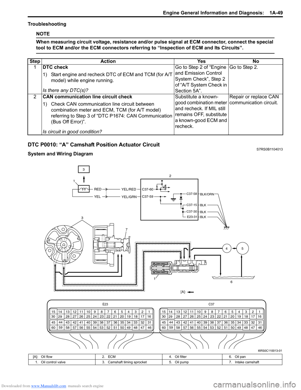
DTC P0010: “A” Camshaft Position Actuator CircuitS7RS0B1104013
System and Wiring DiagramStep Action Yes No
1 DTC check
1) Start engine and recheck DTC of ECM and TCM (for A/T
model) while engine running.
Is there any DTC(s)? Go to Step 2 of “Engine
and Emission Control
System Check”, Step 2
of “A/T System Check in
Section 5A”.Go to Step 2.
2 CAN communication line circuit check
1) Check CAN communication line circuit between
combination meter and ECM, TCM (for A/T model)
referring to Step 3 of “DTC P1674: CAN Communication
(Bus Off Error)”.
Is circuit in good condition? Substitute a known-
good combination meter
and recheck. If MIL still
remains OFF, substitute
a known-good ECM and
recheck.
Repair or replace CAN
communication circuit.
3
7
1[A]: 45
6
C37-58
C37-15
C37-30
E23-31BLK
BLK
BLK/ORN
RED
YEL
YEL/RED
YEL/GRN
C37-60
C37-59
3 2
1
E23 C37
34
1819
567
1011
17
20
47 46
495051
2122
52 16
25 9
24
14
29
55
57 54 53
59
60 58 2
262728
15
30
56 4832 31
34353637
40
42 39 38
44
45 43 41 331
1213
238
34
1819
567
1011
17
20
47 46
495051
2122
52 16
25 9
24
14
29
55
57 54 53
59
60 58 2
262728
15
30
56 4832 31
34353637
40
42 39 38
44
45 43 41 331
1213
238
BLK
I6RS0C110013-01
[A]: Oil flow
2. ECM4. Oil filter6. Oil pan
1. Oil control valve 3. Camshaft timing sprocket5. Oil pump7. Intake camshaft
Page 287 of 1496
Downloaded from www.Manualslib.com manuals search engine Engine Mechanical: 1D-2
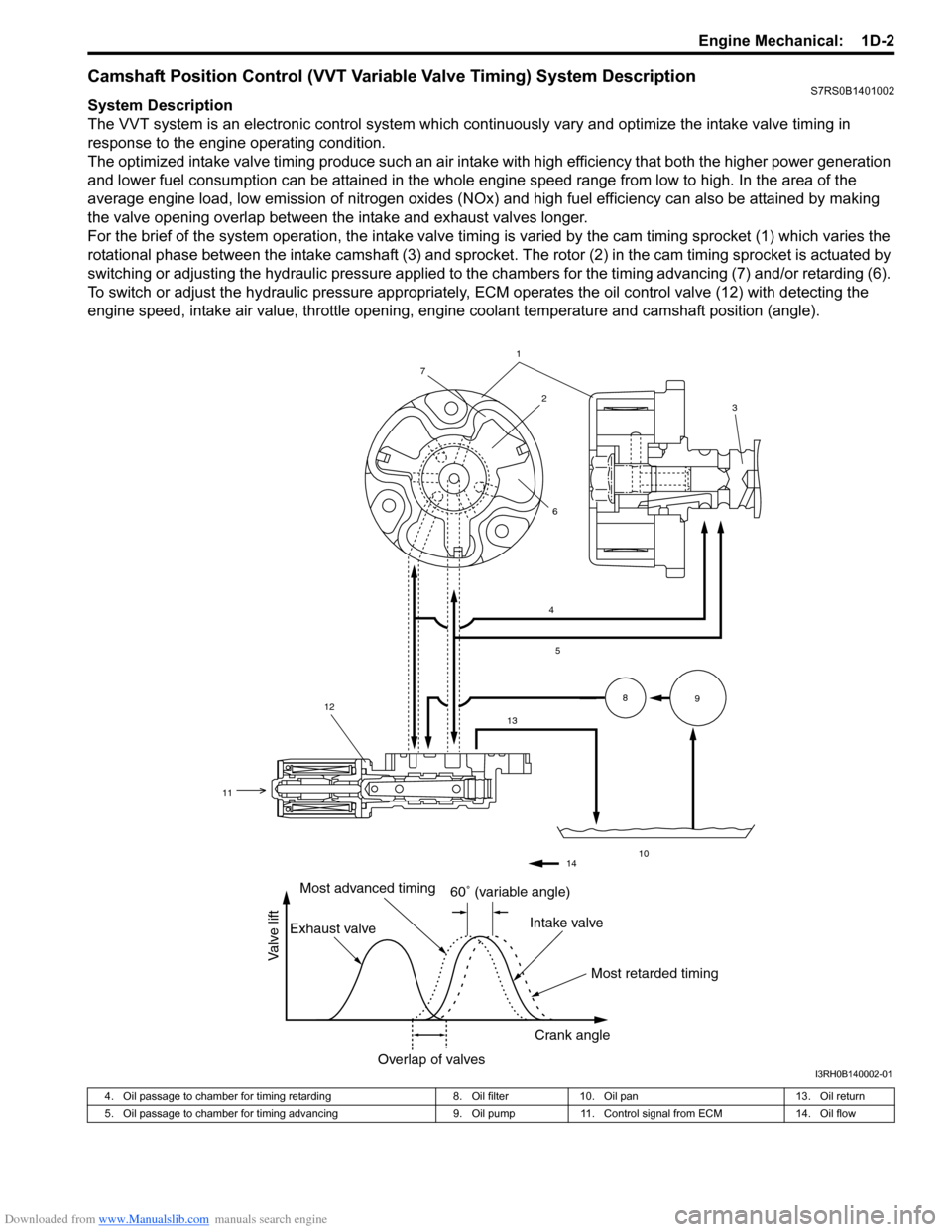
Camshaft Position Control (VVT Variable Valve Timing) System DescriptionS7RS0B1401002
System Description
The VVT system is an electronic control system which continuously vary and optimize the intake valve timing in
response to the engine operating condition.
The optimized intake valve timing produce such an air intake with high efficiency that both the higher power generation
and lower fuel consumption can be attained in the whole engine speed range from low to high. In the area of the
average engine load, low emission of nitrogen oxides (NOx) and high fuel efficiency can also be attained by making
the valve opening overlap between the intake and exhaust valves longer.
For the brief of the system operation, the intake valve timing is varied by the cam timing sprocket (1) which varies the
rotational phase between the intake camshaft (3) and sprocket . The rotor (2) in the cam timing sprocket is actuated by
switching or adjusting the hydraulic pressure applied to the chambers for the timing advancing (7) and/or retarding (6).
To switch or adjust the hydraulic pressure appropriately, ECM operates the oil control valve (12) with detecting the
engine speed, intake air value, throttle opening, engine coolant temperature and camshaft position (angle).
1
4
5
13
10
89
2
7
6
12
11
3
14
60� (variable angle)
Most retarded timing
Most advanced timing
Exhaust valve Intake valve
Crank angle
Overlap of valves
Valve lift
I3RH0B140002-01
4. Oil passage to chamber for timing retarding 8. Oil filter10. Oil pan 13. Oil return
5. Oil passage to chamber for timing advancing 9. Oil pump11. Control signal from ECM 14. Oil flow
Page 306 of 1496
Downloaded from www.Manualslib.com manuals search engine 1D-21 Engine Mechanical:
Timing Chain Cover Removal and InstallationS7RS0B1406013
CAUTION!
• Keep working table, tools and hands clean while overhauling.
• Use special care to handle aluminum parts so as not to damage them.
• Do not expose removed parts to dust. Keep them always clean.
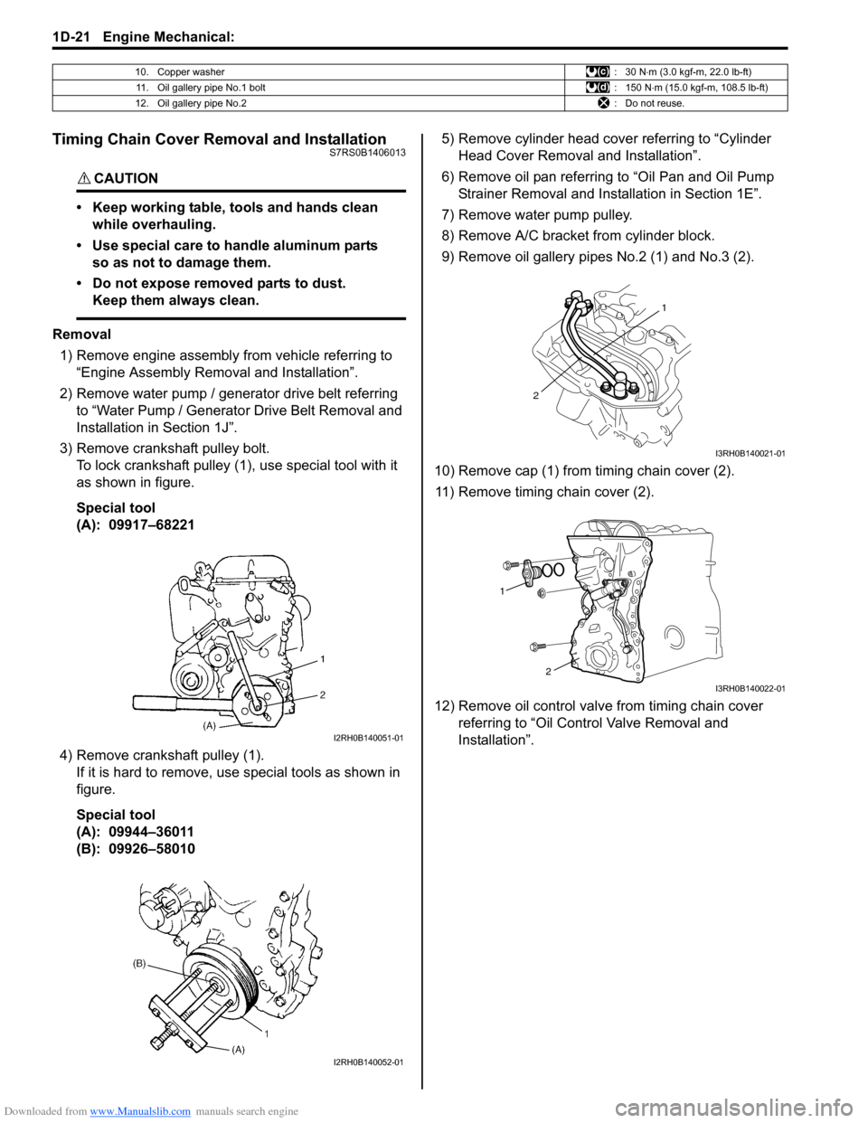
Removal
1) Remove engine assembly from vehicle referring to “Engine Assembly Removal and Installation”.
2) Remove water pump / generator drive belt referring to “Water Pump / Generator Drive Belt Removal and
Installation in Section 1J”.
3) Remove crankshaft pulley bolt. To lock crankshaft pulley (1), use special tool with it
as shown in figure.
Special tool
(A): 09917–68221
4) Remove crankshaft pulley (1). If it is hard to remove, use special tools as shown in
figure.
Special tool
(A): 09944–36011
(B): 09926–58010 5) Remove cylinder head cove
r referring to “Cylinder
Head Cover Removal and Installation”.
6) Remove oil pan referring to “Oil Pan and Oil Pump
Strainer Removal and Inst allation in Section 1E”.
7) Remove water pump pulley.
8) Remove A/C bracket from cylinder block.
9) Remove oil gallery pipe s No.2 (1) and No.3 (2).
10) Remove cap (1) from timing chain cover (2). 11) Remove timing chain cover (2).
12) Remove oil control valve from timing chain cover referring to “Oil Cont rol Valve Removal and
Installation”.
10. Copper washer :30 N⋅m (3.0 kgf-m, 22.0 lb-ft)
11. Oil gallery pipe No.1 bolt : 150 N⋅m (15.0 kgf-m, 108.5 lb-ft)
12. Oil gallery pipe No.2 : Do not reuse.
I2RH0B140051-01
I2RH0B140052-01
1
2
I3RH0B140021-01
1 2
I3RH0B140022-01
Page 308 of 1496
Downloaded from www.Manualslib.com manuals search engine 1D-23 Engine Mechanical:
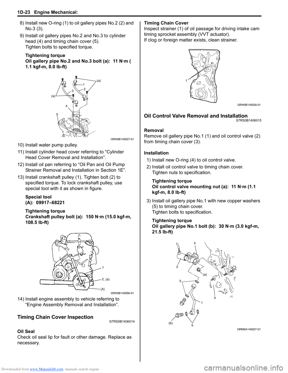
8) Install new O-ring (1) to oil gallery pipes No.2 (2) and
No.3 (3).
9) Install oil gallery pipes No.2 and No.3 to cylinder
head (4) and timing chain cover (5).
Tighten bolts to specified torque.
Tightening torque
Oil gallery pipe No.2 and No.3 bolt (a): 11 N·m (
1.1 kgf-m, 8.0 lb-ft)
10) Install water pump pulley. 11) Install cylinder head cover referring to “Cylinder Head Cover Removal and Installation”.
12) Install oil pan referring to “Oil Pan and Oil Pump
Strainer Removal and Installation in Section 1E”.
13) Install crankshaft pulley (1). Tighten bolt (2) to specified torque. To lock crankshaft pulley, use
special tool with it as shown in figure.
Special tool
(A): 09917–68221
Tightening torque
Crankshaft pulley bolt (a): 150 N·m (15.0 kgf-m,
108.5 lb-ft)
14) Install engine assembly to vehicle referring to “Engine Assembly Removal and Installation”.
Timing Chain Cover InspectionS7RS0B1406014
Oil Seal
Check oil seal lip for fault or other damage. Replace as
necessary. Timing Chain Cover
Inspect strainer (1) of oil passage for driving intake cam
timing sprocket assembly (VVT actuator).
If clog or foreign matter exists, clean strainer.
Oil Control Valve Removal and InstallationS7RS0B1406015
Removal
Remove oil gallery pipe No.1
(1) and oil control valve (2)
from timing chain cover (3).
Installation
1) Install new O-ring (4) to oil control valve.
2) Install oil control valve to timing chain cover. Tighten nuts to specification.
Tightening torque
Oil control valve mounting nut (a): 11 N·m (1.1
kgf-m, 8.0 lb-ft)
3) Install oil gallery pipe No .1 with new copper washers
(5) to timing chain cover.
Tighten bolts to specification.
Tightening torque
Oil gallery pipe No.1 bolt (b): 30 N·m (3.0 kgf-m,
21.5 lb-ft)
(a)
(a) 1
2
3
4
5
I3RH0B140027-01
I2RH0B140056-01
1
I3RH0B140028-01
1
5
(b) 3
(a)
2 4
5
I3RM0A140027-01