position lights SUZUKI SWIFT 2007 2.G Service Workshop Manual
[x] Cancel search | Manufacturer: SUZUKI, Model Year: 2007, Model line: SWIFT, Model: SUZUKI SWIFT 2007 2.GPages: 1496, PDF Size: 34.44 MB
Page 43 of 1496
Downloaded from www.Manualslib.com manuals search engine Maintenance and Lubrication: 0B-13
Brake
Foot brake
Check the following:
• that brake pedal has proper travel,
• that brake works properly,
• that it is free from noise,
• that vehicle does not pull to one side when brake is applied.
• and that brake do not drag.
Parking brake
Check that lever has proper travel.
WARNING!
With vehicle parked on a fairly steep slope,
make sure nothing is in the way downhill to
avoid any personal injury or property
damage. Be prepared to apply regular brake
quickly even if vehicle should start to move.
Check to ensure that parking brake is fully effective
when the vehicle is stopped on the safe slope and brake
lever is pulled all the way.
Steering
• Check to ensure that steering wheel is free from instability, or abnormally heavy feeling. • Check that the vehicle does not wander or pull to one
side.
Engine
• Check that engine responds readily at all speeds.
• Check that engine is free from abnormal noise and abnormal vibration.
Body, Wheels and Power Transmitting System
Check that body, wheels and power transmitting system
are free from abnormal noise and abnormal vibration or
any other abnormal condition.
Meters and Gauge
Check that speedometer, odometer, fuel meter,
temperature gauge, etc. are operating accurately.
Lights
Check that all lights operate properly.
Windshield Defroster
Periodically check that ai r comes out from defroster
outlet when operating heater or air conditioning.
Set mode control lever to defroster position and fan
switch lever to “HI” position for this check.
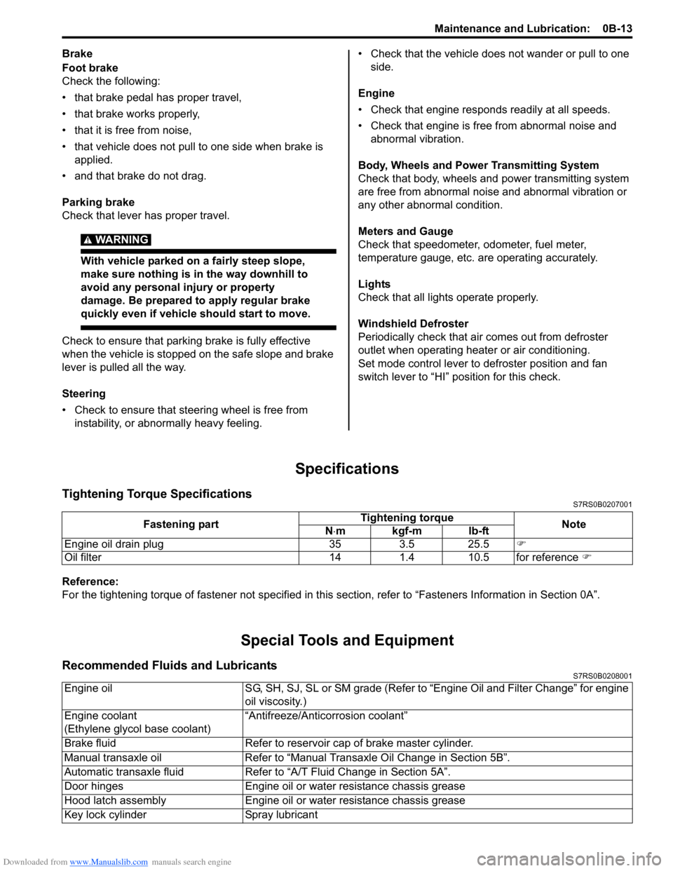
Specifications
Tightening Torque SpecificationsS7RS0B0207001
Reference:
For the tightening torque of fastener not specified in this section, refer to “Fasteners Information in Section 0A”.
Special Tools and Equipment
Recommended Fluids and LubricantsS7RS0B0208001
Fastening part Tightening torque
Note
N ⋅mkgf-mlb-ft
Engine oil drain plug 35 3.5 25.5 �)
Oil filter 14 1.4 10.5 for reference �)
Engine oilSG, SH, SJ, SL or SM grade (Refer to “Engine Oil and Filter Change” for engine
oil viscosity.)
Engine coolant
(Ethylene glycol base coolant) “Antifreeze/Antico
rrosion coolant”
Brake fluid Refer to reservoir cap of brake master cylinder.
Manual transaxle oil Refer to “Manual Transaxle Oil Change in Section 5B”.
Automatic transaxle fluid Refer to “A/T Fluid Change in Section 5A”.
Door hinges Engine oil or water resistance chassis grease
Hood latch assembly Engine oil or water resistance chassis grease
Key lock cylinder Spray lubricant
Page 54 of 1496
Downloaded from www.Manualslib.com manuals search engine 1A-4 Engine General Information and Diagnosis:
Driving Cycle
A “Driving Cycle” consists of engine startup and engine
shutoff.
2 Driving Cycle Detection Logic
The malfunction detected in the first driving cycle is
stored in ECM memory (in t he form of pending DTC) but
the malfunction indicator lamp does not light at this time.
It lights up at the second detection of same malfunction
also in the next driving cycle.
Pending DTC
Pending DTC means a DTC detected and stored
temporarily at 1 driving cycle of the DTC which is
detected in the 2 driving cycle detection logic.
Freeze Frame Data
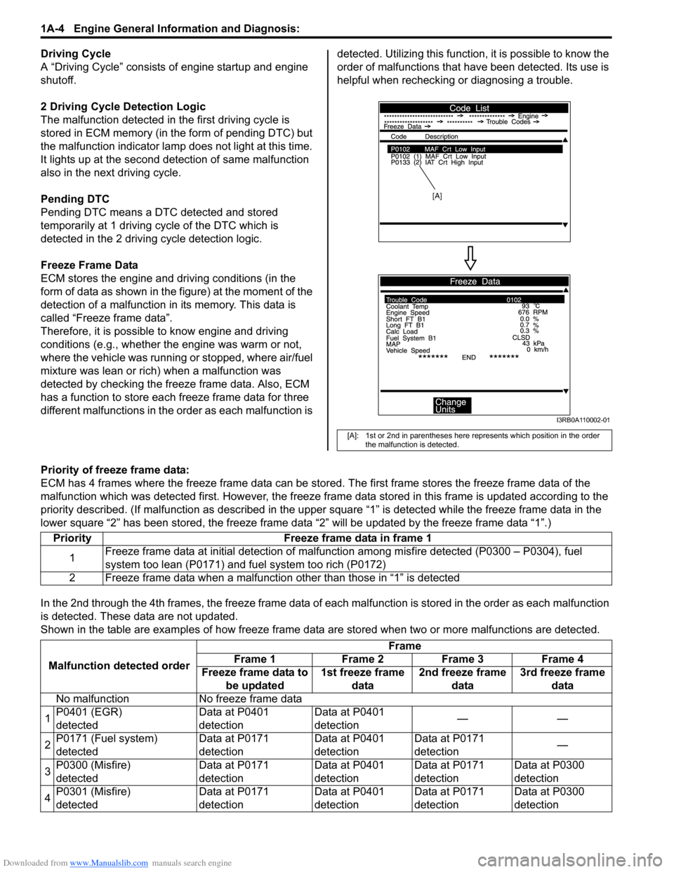
ECM stores the engine and driving conditions (in the
form of data as shown in the figure) at the moment of the
detection of a malfunction in its memory. This data is
called “Freeze frame data”.
Therefore, it is possible to know engine and driving
conditions (e.g., whether the engine was warm or not,
where the vehicle was running or stopped, where air/fuel
mixture was lean or rich) when a malfunction was
detected by checking the freeze frame data. Also, ECM
has a function to store each freeze frame data for three
different malfunctions in the order as each malfunction is detected. Utilizing this function,
it is possible to know the
order of malfunctions that ha ve been detected. Its use is
helpful when rechecking or diagnosing a trouble.
Priority of freeze frame data:
ECM has 4 frames where the freeze frame data can be stor ed. The first frame stores the freeze frame data of the
malfunction which was detected first. Howe ver, the freeze frame data stored in this frame is updated according to the
priority described. (If malfunction as described in the upper square “1” is detected while the freeze frame data in the
lower square “2” has been stored, the freeze frame data “2” will be updated by the freeze frame data “1”.)
In the 2nd through the 4th frames, the freeze frame data of each malfunction is stored in the order as each malfunction
is detected. These data are not updated.
Shown in the table are examples of how freeze frame data are stored when two or more malfunctions are detected.
[A]: 1st or 2nd in parentheses here represents which position in the order
the malfunction is detected.
[A]
I3RB0A110002-01
Priority Freeze frame data in frame 1
1 Freeze frame data at initial detection of malfuncti
on among misfire detected (P0300 – P0304), fuel
system too lean (P0171) and fuel system too rich (P0172)
2 Freeze frame data when a malfunctio n other than those in “1” is detected
Malfunction detected order Frame
Frame 1 Frame 2 Frame 3 Frame 4
Freeze frame data to be updated 1st freeze frame
data 2nd freeze frame
data 3rd freeze frame
data
No malfunction No freeze frame data
1 P0401 (EGR)
detected Data at P0401
detectionData at P0401
detection
——
2 P0171 (Fuel system)
detected Data at P0171
detectionData at P0401
detectionData at P0171
detection
—
3 P0300 (Misfire)
detected Data at P0171
detectionData at P0401
detectionData at P0171
detectionData at P0300
detection
4 P0301 (Misfire)
detected Data at P0171
detectionData at P0401
detectionData at P0171
detectionData at P0300
detection
Page 76 of 1496
Downloaded from www.Manualslib.com manuals search engine 1A-26 Engine General Information and Diagnosis:
DTC CheckS7RS0B1104003
NOTE
• There are two types of OBD system depending on the vehicle specification.
For details, refer to “Precaution on On-
Board Diagnostic (OBD) System”.
• The MIL is turned on when the ECM and/or TCM detect malfunction(s). Each ECM and
TCM stores diagnostic information as the
diagnostic trouble code (DTC) in its
memory and outputs th e DTC to the scan
tool.
Therefore, check both of the ECM and TCM
for any DTC with the SUZUKI scan tool
because the DTC stored in ECM and TCM
is not read and displayed at a time.
However, each of the ECM and TCM needs
not to be checked with the generic scan
tool because the DTC stored in ECM and
TCM is read and displayed at a time.
Using Scan Tool
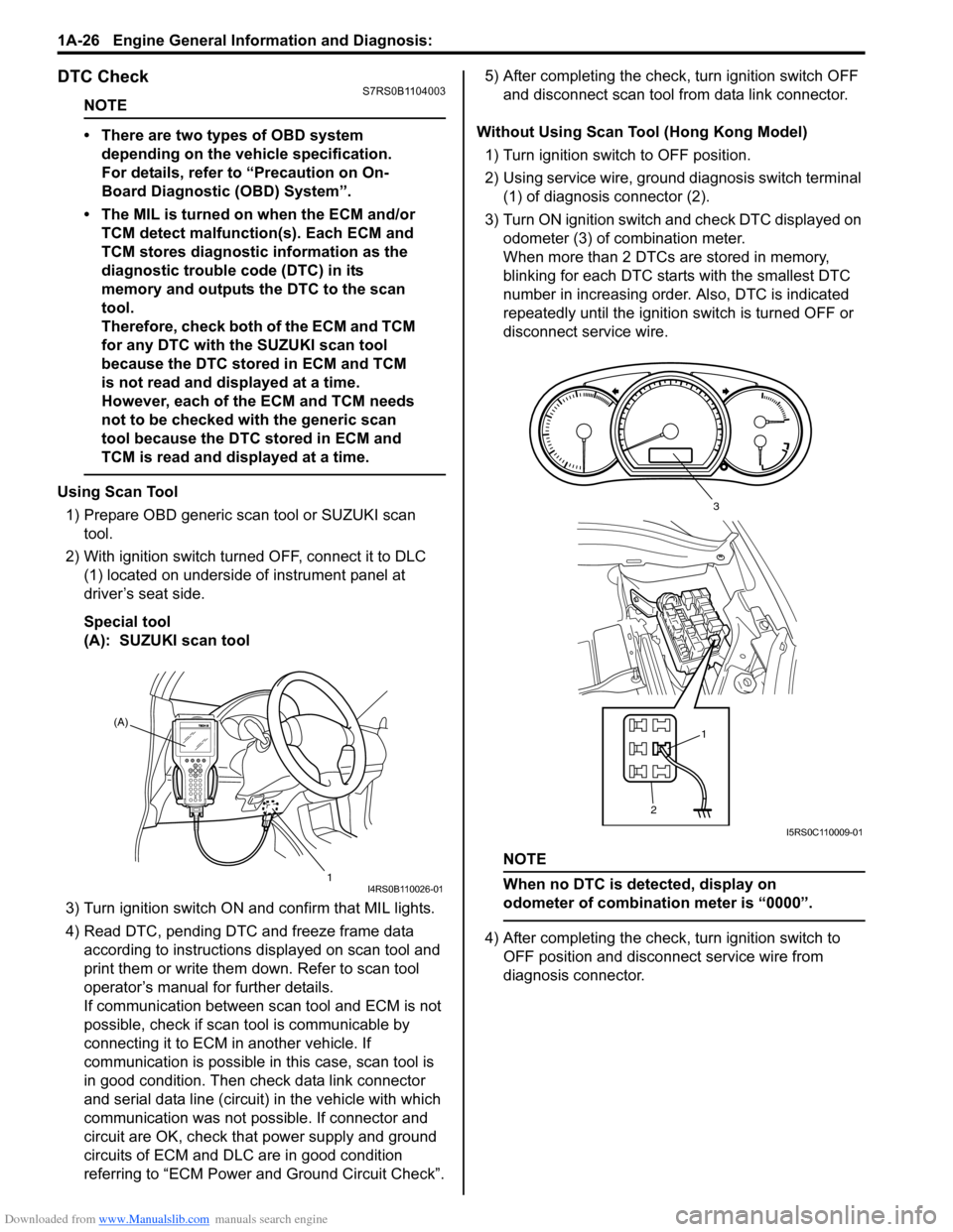
1) Prepare OBD generic scan tool or SUZUKI scan tool.
2) With ignition switch turned OFF, connect it to DLC (1) located on underside of instrument panel at
driver’s seat side.
Special tool
(A): SUZUKI scan tool
3) Turn ignition switch ON and confirm that MIL lights.
4) Read DTC, pending DTC and freeze frame data according to instructions displayed on scan tool and
print them or write them down. Refer to scan tool
operator’s manual for further details.
If communication between scan tool and ECM is not
possible, check if scan tool is communicable by
connecting it to ECM in another vehicle. If
communication is possible in this case, scan tool is
in good condition. Then check data link connector
and serial data line (circuit) in the vehicle with which
communication was not possible. If connector and
circuit are OK, check that power supply and ground
circuits of ECM and DLC are in good condition
referring to “ECM Power and Ground Circuit Check”. 5) After completing the check,
turn ignition switch OFF
and disconnect scan tool from data link connector.
Without Using Scan Tool (Hong Kong Model) 1) Turn ignition switch to OFF position.
2) Using service wire, ground diagnosis switch terminal (1) of diagnosis connector (2).
3) Turn ON ignition switch and check DTC displayed on
odometer (3) of combination meter.
When more than 2 DTCs are stored in memory,
blinking for each DTC star ts with the smallest DTC
number in increasing order. Also, DTC is indicated
repeatedly until the ignition switch is turned OFF or
disconnect service wire.
NOTE
When no DTC is detected, display on
odometer of combinatio n meter is “0000”.
4) After completing the check, turn ignition switch to
OFF position and disconnect service wire from
diagnosis connector.
(A)
1
I4RS0B110026-01
21
3
I5RS0C110009-01
Page 77 of 1496
Downloaded from www.Manualslib.com manuals search engine Engine General Information and Diagnosis: 1A-27
DTC ClearanceS7RS0B1104004
NOTE
There are two types of OBD system
depending on the vehicle specification.
For details, refer to “Precaution on On-Board
Diagnostic (OBD) System”.
Using Scan Tool1) Connect OBD generic scan to ol or SUZUKI scan tool
to data link connector in the same manner as when
making this connection for DTC check.
2) Turn ignition switch OFF and then ON.
3) Erase DTC and pending DTC according to instructions displayed on scan tool. Refer to scan
tool operator’s manual for further details.
4) After completing the clear ance, turn ignition switch
OFF and disconnect scan tool from data link
connector.
NOTE
DTC and freeze frame data stored in ECM
memory are also cleared in the following
cases. Be careful not to clear them before
keeping their record.
• When power to ECM is cut off (by disconnecting battery cable, removing
fuse or disconnecting ECM connectors).
• When the same malfunction (DTC) is not detected again during 40 engine warm-up
cycles. (See “Warm-Up Cycle” of “On-
Board Diagnostic System Description”.)
Without Using Scan Tool (Hong Kong Model)
1) Turn ignition switch to OFF position.
2) Disconnect battery negative cable for specified time below to erase diagnostic trouble code stored in
ECM memory and reconnect it.
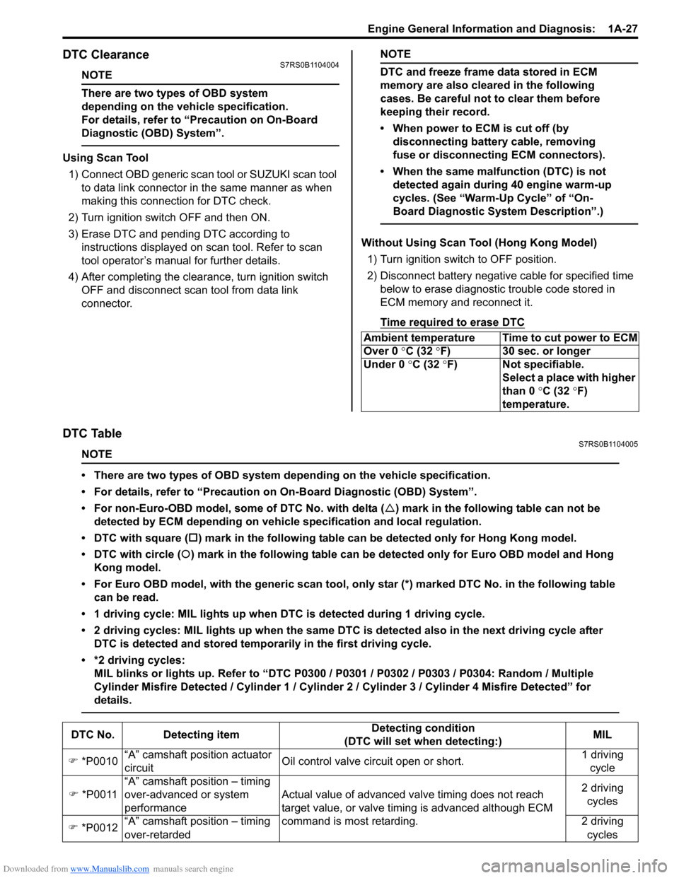
Time required to erase DTC
DTC TableS7RS0B1104005
NOTE
• There are two types of OBD system depending on the vehicle specification.
• For details, refer to “Precaution on On-Board Diagnostic (OBD) System”.
• For non-Euro-OBD model, some of DTC No. with delta ( �U) mark in the following table can not be
detected by ECM depending on vehicl e specification and local regulation.
• DTC with square ( �†) mark in the following table can be detected only for Hong Kong model.
• DTC with circle ( �{) mark in the following table can be detected only for Euro OBD model and Hong
Kong model.
• For Euro OBD model, with the generic scan tool, onl y star (*) marked DTC No. in the following table
can be read.
• 1 driving cycle: MIL lights up when DTC is detected during 1 driving cycle.
• 2 driving cycles: MIL lights up when the same DTC is detected also in the next driving cycle after DTC is detected and stored temporarily in the first driving cycle.
• *2 driving cycles: MIL blinks or lights up. Refer to “DTC P0300 / P0301 / P0302 / P0303 / P0304: Random / Multiple
Cylinder Misfire Detected / Cylinder 1 / Cylinder 2 / Cylinder 3 / Cylinder 4 Misfire Detected” for
details.
Ambient temperature Time to cut power to ECM
Over 0 °C (32 ° F) 30 sec. or longer
Under 0 °C (32 °F) Not specifiable.
Select a place with higher
than 0 °C (32 °F)
temperature.
DTC No. Detecting item Detecting condition
(DTC will set when detecting:) MIL
�) *P0010 “A” camshaft position actuator
circuit Oil control valve circuit open or short. 1 driving
cycle
�) *P0011 “A” camshaft position – timing
over-advanced or system
performance Actual value of advanced va
lve timing does not reach
target value, or valve timi ng is advanced although ECM
command is most retarding. 2 driving
cycles
�) *P0012 “A” camshaft position – timing
over-retarded 2 driving
cycles
Page 98 of 1496
Downloaded from www.Manualslib.com manuals search engine 1A-48 Engine General Information and Diagnosis:
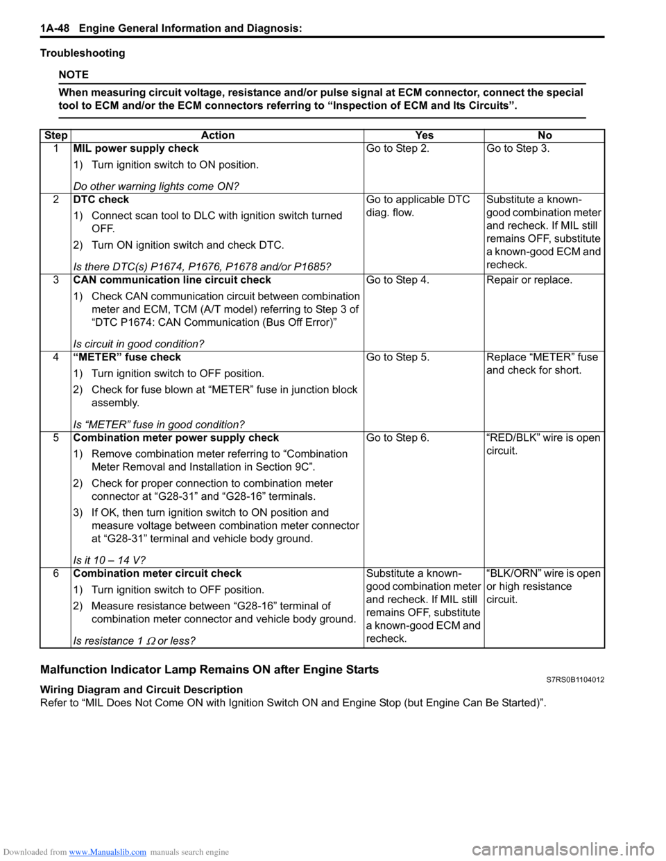
Troubleshooting
NOTE
When measuring circuit voltage, resistance and/or pulse signal at ECM connector, connect the special
tool to ECM and/or the ECM connectors referri ng to “Inspection of ECM and Its Circuits”.
Malfunction Indicator Lamp Remains ON after Engine StartsS7RS0B1104012
Wiring Diagram and Circuit Description
Refer to “MIL Does Not Come ON wit h Ignition Switch ON and Engine Stop (but Engine Can Be Started)”.
Step
Action YesNo
1 MIL power supply check
1) Turn ignition switch to ON position.
Do other warning lights come ON? Go to Step 2.
Go to Step 3.
2 DTC check
1) Connect scan tool to DLC with ignition switch turned
OFF.
2) Turn ON ignition switch and check DTC.
Is there DTC(s) P1674, P1676, P1678 and/or P1685? Go to applicable DTC
diag. flow.
Substitute a known-
good combination meter
and recheck. If MIL still
remains OFF, substitute
a known-good ECM and
recheck.
3 CAN communication line circuit check
1) Check CAN communication circuit between combination
meter and ECM, TCM (A/T model) referring to Step 3 of
“DTC P1674: CAN Communication (Bus Off Error)”
Is circuit in good condition? Go to Step 4.
Repair or replace.
4 “METER” fuse check
1) Turn ignition switch to OFF position.
2) Check for fuse blown at “M ETER” fuse in junction block
assembly.
Is “METER” fuse in good condition? Go to Step 5.
Replace “METER” fuse
and check for short.
5 Combination meter power supply check
1) Remove combination meter referring to “Combination
Meter Removal and Installation in Section 9C”.
2) Check for proper connection to combination meter connector at “G28-31” and “G28-16” terminals.
3) If OK, then turn ignition switch to ON position and measure voltage between combination meter connector
at “G28-31” terminal and vehicle body ground.
Is it 10 – 14 V? Go to Step 6.
“RED/BLK” wire is open
circuit.
6 Combination meter circuit check
1) Turn ignition switch to OFF position.
2) Measure resistance between “G28-16” terminal of
combination meter connector and vehicle body ground.
Is resistance 1
Ω or less? Substitute a known-
good combination meter
and recheck. If MIL still
remains OFF, substitute
a known-good ECM and
recheck.
“BLK/ORN” wire is open
or high resistance
circuit.
Page 190 of 1496
Downloaded from www.Manualslib.com manuals search engine 1A-140 Engine General Information and Diagnosis:
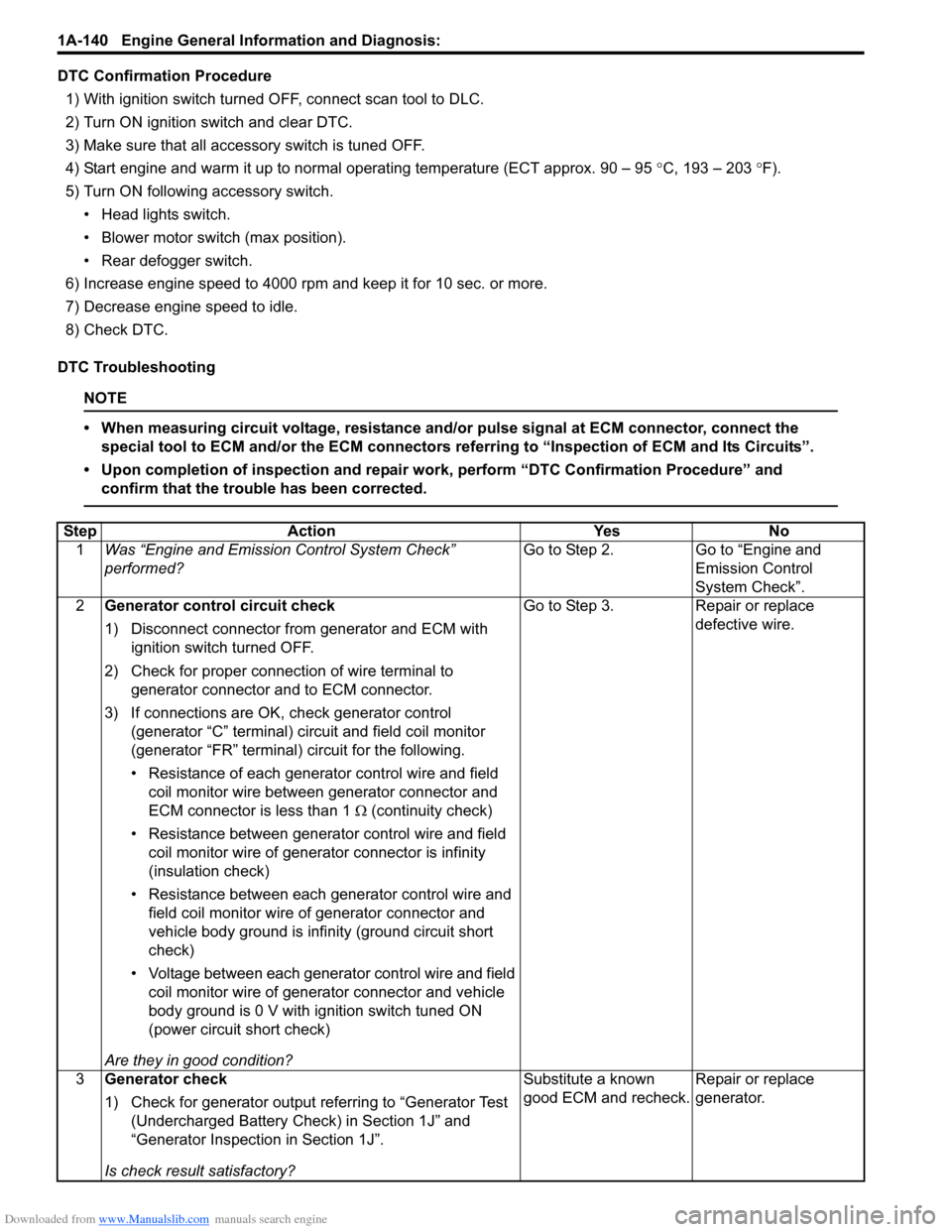
DTC Confirmation Procedure1) With ignition switch turned OFF, connect scan tool to DLC.
2) Turn ON ignition switch and clear DTC.
3) Make sure that all accessory switch is tuned OFF.
4) Start engine and warm it up to normal operating temperature (ECT approx. 90 – 95 °C, 193 – 203 °F).
5) Turn ON following accessory switch. • Head lights switch.
• Blower motor switch (max position).
• Rear defogger switch.
6) Increase engine speed to 4000 rpm and keep it for 10 sec. or more.
7) Decrease engine speed to idle.
8) Check DTC.
DTC Troubleshooting
NOTE
• When measuring circuit voltage, resistance and/ or pulse signal at ECM connector, connect the
special tool to ECM and/or the ECM connectors re ferring to “Inspection of ECM and Its Circuits”.
• Upon completion of inspection and repair work, perform “DTC Confirmation Procedure” and confirm that the trouble has been corrected.
Step Action YesNo
1 Was “Engine and Emission Control System Check”
performed? Go to Step 2.
Go to “Engine and
Emission Control
System Check”.
2 Generator control circuit check
1) Disconnect connector from generator and ECM with
ignition switch turned OFF.
2) Check for proper connection of wire terminal to generator connector and to ECM connector.
3) If connections are OK, check generator control (generator “C” terminal) circuit and field coil monitor
(generator “FR” terminal) circuit for the following.
• Resistance of each generato r control wire and field
coil monitor wire between generator connector and
ECM connector is less than 1 Ω (continuity check)
• Resistance between generator control wire and field coil monitor wire of generator connector is infinity
(insulation check)
• Resistance between each generator control wire and field coil monitor wire of generator connector and
vehicle body ground is infinity (ground circuit short
check)
• Voltage between each generator control wire and field
coil monitor wire of generator connector and vehicle
body ground is 0 V with ignition switch tuned ON
(power circuit short check)
Are they in good condition? Go to Step 3.
Repair or replace
defective wire.
3 Generator check
1) Check for generator output referring to “Generator Test
(Undercharged Battery Check) in Section 1J” and
“Generator Inspection in Section 1J”.
Is check result satisfactory? Substitute a known
good ECM and recheck.
Repair or replace
generator.
Page 191 of 1496
Downloaded from www.Manualslib.com manuals search engine Engine General Information and Diagnosis: 1A-141
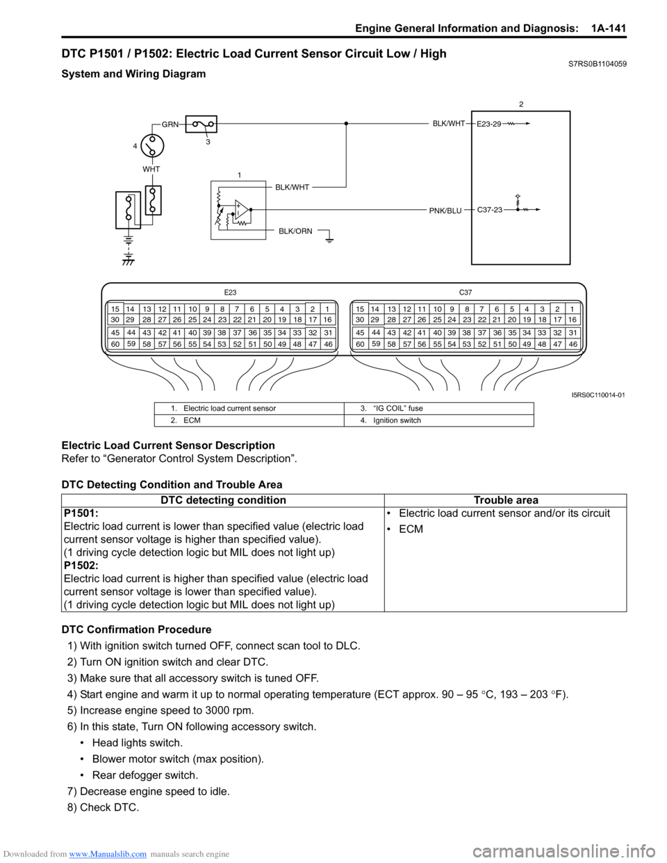
DTC P1501 / P1502: Electric Load Current Sensor Circuit Low / HighS7RS0B1104059
System and Wiring Diagram
Electric Load Current Sensor Description
Refer to “Generator Control System Description”.
DTC Detecting Condition and Trouble Area
DTC Confirmation Procedure1) With ignition switch turned OFF, connect scan tool to DLC.
2) Turn ON ignition switch and clear DTC.
3) Make sure that all accessory switch is tuned OFF.
4) Start engine and warm it up to normal operating temperature (ECT approx. 90 – 95 °C, 193 – 203 °F).
5) Increase engine speed to 3000 rpm.
6) In this state, Turn ON following accessory switch.
• Head lights switch.
• Blower motor switch (max position).
• Rear defogger switch.
7) Decrease engine speed to idle.
8) Check DTC.
E23 C37
34
1819
567
1011
17
20
47 46
495051
2122
52 16
25 9
24
14
29
55
57 54 53
59
60 58 2
262728
15
30
56 4832 31
34353637
40
42 39 38
44
45 43 41 331
1213
238
34
1819
567
1011
17
20
47 46
495051
2122
52 16
25 9
24
14
29
55
57 54 53
59
60 58 2
262728
15
30
56 4832 31
34353637
40
42 39 38
44
45 43 41 331
1213
238
BLK/WHT
WHT
GRN
4
3 2
E23-29
1
C37-23PNK/BLU
BLK/ORN
BLK/WHT
I5RS0C110014-01
1. Electric load current sensor
3. “IG COIL” fuse
2. ECM 4. Ignition switch
DTC detecting condition Trouble area
P1501:
Electric load current is lower th an specified value (electric load
current sensor voltage is higher than specified value).
(1 driving cycle detection logic but MIL does not light up)
P1502:
Electric load current is higher than specified value (electric load
current sensor voltage is lo wer than specified value).
(1 driving cycle detection logic but MIL does not light up) • Electric load current sensor and/or its circuit
•ECM
Page 506 of 1496
Downloaded from www.Manualslib.com manuals search engine 4A-8 Brake Control System and Diagnosis:
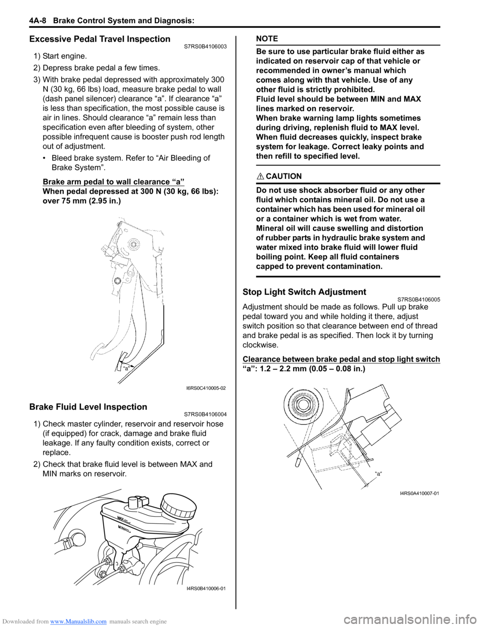
Excessive Pedal Travel InspectionS7RS0B4106003
1) Start engine.
2) Depress brake pedal a few times.
3) With brake pedal depressed with approximately 300 N (30 kg, 66 lbs) load, measure brake pedal to wall
(dash panel silencer) clearance “a”. If clearance “a”
is less than specification, the most possible cause is
air in lines. Should clearance “a” remain less than
specification even after bleeding of system, other
possible infrequent cause is booster push rod length
out of adjustment.
• Bleed brake system. Refer to “Air Bleeding of Brake System”.
Brake arm pedal to wall clearance “a”
When pedal depressed at 300 N (30 kg, 66 lbs):
over 75 mm (2.95 in.)
Brake Fluid Level InspectionS7RS0B4106004
1) Check master cylinder, reservoir and reservoir hose (if equipped) for crack, damage and brake fluid
leakage. If any faulty condition exists, correct or
replace.
2) Check that brake fluid level is between MAX and MIN marks on reservoir.
NOTE
Be sure to use particular brake fluid either as
indicated on reservoir cap of that vehicle or
recommended in owner’s manual which
comes along with that vehicle. Use of any
other fluid is strictly prohibited.
Fluid level should be between MIN and MAX
lines marked on reservoir.
When brake warning lamp lights sometimes
during driving, replenis h fluid to MAX level.
When fluid decreases quickly, inspect brake
system for leakage. Correct leaky points and
then refill to specified level.
CAUTION!
Do not use shock absorber fluid or any other
fluid which contains mineral oil. Do not use a
container which has been used for mineral oil
or a container which is wet from water.
Mineral oil will cause swelling and distortion
of rubber parts in hydraulic brake system and
water mixed into brake fluid will lower fluid
boiling point. Keep all fluid containers
capped to prevent contamination.
Stop Light Switch AdjustmentS7RS0B4106005
Adjustment should be made as follows. Pull up brake
pedal toward you and while holding it there, adjust
switch position so that clea rance between end of thread
and brake pedal is as specified. Then lock it by turning
clockwise.
Clearance between brake pedal and stop light switch
“a”: 1.2 – 2.2 mm (0.05 – 0.08 in.)
I6RS0C410005-02
I4RS0B410006-01
I4RS0A410007-01
Page 552 of 1496
Downloaded from www.Manualslib.com manuals search engine 4E-13 ABS:
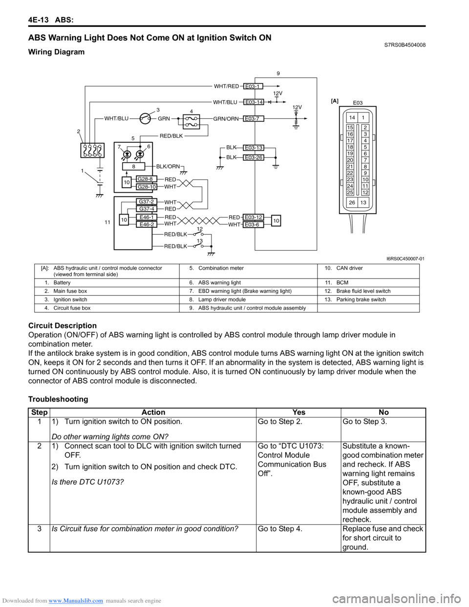
ABS Warning Light Does Not Come ON at Ignition Switch ONS7RS0B4504008
Wiring Diagram
Circuit Description
Operation (ON/OFF) of ABS warning light is controlled by ABS contro l module through lamp driver module in
combination meter.
If the antilock brake system is in good condition, ABS control module turns ABS warning light ON at the ignition switch
ON, keeps it ON for 2 seconds and then turns it OFF. If an abnormality in the system is detected, ABS warning light is
turned ON continuously by ABS control module. Also, it is turned ON continuously by la mp driver module when the
connector of ABS control module is disconnected.
Troubleshooting
WHT/BLU
BLK 12V
9
BLK
E03-14
E03-13
E03-26
WHT/RED
GRN/ORNE03-7WHT/BLUGRN
1
2
3
48
RED/BLK
76
5
10
E03-112V[A]
E03
15
16
17
18
19
20
21
22
23
24
25 2
3
4
5
6
7
8
9
10
11
12
1
13
14
26
BLK/ORN
E03-12
E03-6
REDWHT
10
G28-8
G28-10
REDWHTE46-1
E46-2
RED/BLK
RED/BLK
RED
RED
WHT
WHT
12
13
11
10
G37-2
G37-4
I6RS0C450007-01
[A]: ABS hydraulic unit / control module connector (viewed from terminal side) 5. Combination meter 10. CAN driver
1. Battery 6. ABS warning light 11. BCM
2. Main fuse box 7. EBD warning light (Brake warning light) 12. Brake fluid level switch
3. Ignition switch 8. Lamp driver module 13. Parking brake switch
4. Circuit fuse box 9. ABS hydraulic unit / control module assembly
Step Action YesNo
1 1) Turn ignition switch to ON position.
Do other warning lights come ON? Go to Step 2.
Go to Step 3.
2 1) Connect scan tool to DLC with ignition switch turned OFF.
2) Turn ignition switch to ON position and check DTC.
Is there DTC U1073? Go to “DTC U1073:
Control Module
Communication Bus
Off”.
Substitute a known-
good combination meter
and recheck. If ABS
warning light remains
OFF, substitute a
known-good ABS
hydraulic unit / control
module assembly and
recheck.
3 Is Circuit fuse fo r combination meter in good condition? Go to Step 4.Replace fuse and check
for short circuit to
ground.
Page 631 of 1496
Downloaded from www.Manualslib.com manuals search engine Electronic Stability Program: 4F-57
3) Remove front brake pipe referring to “Front Brake Hose / Pipe Removal and In stallation in Section 4A”.
4) Remove ESP ® hydraulic unit / control module with
bracket from vehicle by removing bracket bolts.
5) Remove bolt (4) and pull out ESP ® hydraulic unit /
control module assembly (1) from bracket (3) using
flat end rod or the like (2).
Installation 1) Install hydraulic unit / co ntrol module assembly and
by reversing removal procedure.
Tightening torque
Brake pipe flare nut: 16 N·m (1.6 kgf-m, 11.5 lb-
ft)
ESP ® hydraulic unit / control module assembly
bolt: 9 N·m (0.9 kgf-m, 6.5 lb-ft)
ESP ® hydraulic unit / control module assembly
bracket bolt: 25 N·m (2.5 kgf-m, 18.0 lb-ft)
2) Bleed air from brake system referring to “Air Bleeding of Brake System in Section 4A”.
3) Check each installed part for fluid leakage.
4) Connect SUZUKI Scan Tool.
5) Turn ignition switch to ON position. And SLIP indicator lamp flush. (Other than replace with new
one) If other than SLIP indicator lamp light, check
DTC and repair it.
6) Turn ignition switch to ON position. And ESP®
warning lamp, SLIP indicator lamp, ESP ® OFF
lamp, Brake warning lamp lights and ABS warning
lamp flush. (Replace new one)
7) Check DTC.
NOTE
If any DTC(s) other than C1075, C1076 or
C1078 are detected, sensor calibration can
not be completed. Repair the detected it(s)
first.
8) Perform “Sensor Calibration”.
9) Perform “ESP ® Hydraulic Unit Operation Check”.
10) Turn ignition switch to OFF position once and then
ON position. In this state, make sure that indicator
light and warning light turns off.
11) Check DTC(s) are not stored in hydraulic unit / control module.
Front / Rear Wheel Speed Sensor On-Vehicle
Inspection
S7RS0B4606028
CAUTION!
Incorrect voltage and/or wrong connection
cause damage to wheel speed sensor.
Output Voltage Inspection
1) Disconnect negative (–) cable from battery.
2) Hoist vehicle a little.
3) Disconnect wheel speed sensor connector.
4) Disconnect wheel speed grommet from vehicle body.
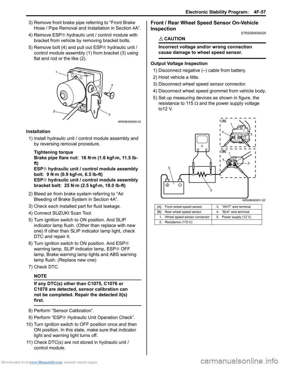
5) Set up measuring devices as shown in figure, the resistance to 115 Ω and the power supply voltage
to12 V.
4
1
2 3
I6RS0B460030-02
[A]: Front wheel speed sensor 3. “WHT” wire terminal
[B]: Rear wheel speed sensor 4. “BLK” wire terminal
1. Wheel speed sensor connector 5. Power supply (12 V)
2. Resistance (115 Ω)
V
2
5
4 1
3
43
1
[A]
[B]
I6RS0B460031-02