air con switch SUZUKI SWIFT 2008 2.G Service Workshop Manual
[x] Cancel search | Manufacturer: SUZUKI, Model Year: 2008, Model line: SWIFT, Model: SUZUKI SWIFT 2008 2.GPages: 1496, PDF Size: 34.44 MB
Page 565 of 1496
Downloaded from www.Manualslib.com manuals search engine ABS: 4E-26
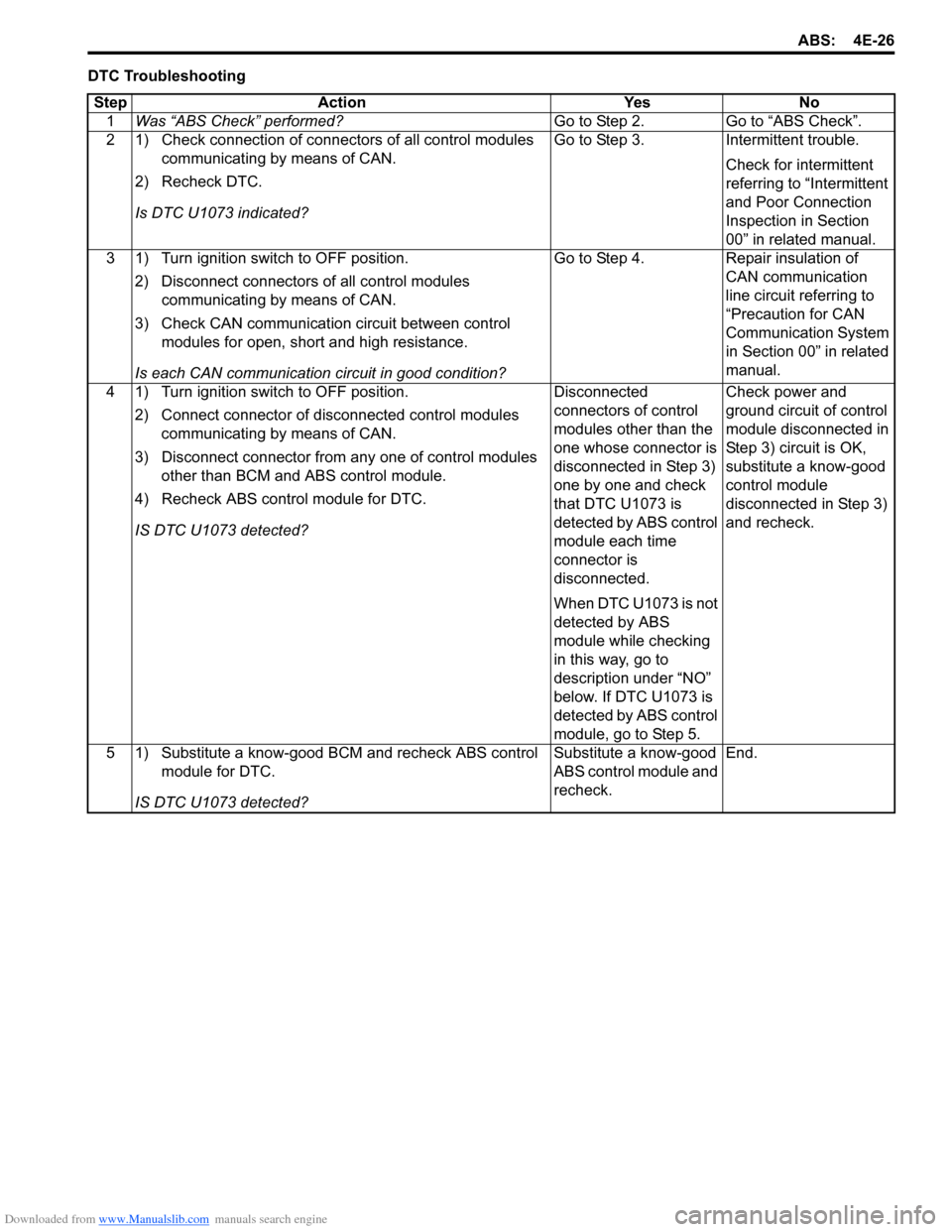
DTC TroubleshootingStep Action Yes No 1 Was “ABS Check” performed? Go to Step 2. Go to “ABS Check”.
2 1) Check connection of connectors of all control modules communicating by means of CAN.
2) Recheck DTC.
Is DTC U1073 indicated? Go to Step 3. Intermittent trouble.
Check for intermittent
referring to “Intermittent
and Poor Connection
Inspection in Section
00” in related manual.
3 1) Turn ignition switch to OFF position.
2) Disconnect connectors of all control modules communicating by means of CAN.
3) Check CAN communication circuit between control modules for open, short and high resistance.
Is each CAN communication circuit in good condition? Go to Step 4. Repair insulation of
CAN communication
line circuit referring to
“Precaution for CAN
Communication System
in Section 00” in related
manual.
4 1) Turn ignition switch to OFF position.
2) Connect connector of disconnected control modules communicating by means of CAN.
3) Disconnect connector from any one of control modules other than BCM and ABS control module.
4) Recheck ABS contro l module for DTC.
IS DTC U1073 detected? Disconnected
connectors of control
modules other than the
one whose connector is
disconnected in Step 3)
one by one and check
that DTC U1073 is
detected by ABS control
module each time
connector is
disconnected.
When DTC U1073 is not
detected by ABS
module while checking
in this way, go to
description under “NO”
below. If DTC U1073 is
detected by ABS control
module, go to Step 5.Check power and
ground circuit of control
module disconnected in
Step 3) circuit is OK,
substitute a know-good
control module
disconnected in Step 3)
and recheck.
5 1) Substitute a know-good BCM and recheck ABS control module for DTC.
IS DTC U1073 detected? Substitute a know-good
ABS control module and
recheck.
End.
Page 566 of 1496
Downloaded from www.Manualslib.com manuals search engine 4E-27 ABS:
DTC U1100: Lost Communication with ECM (Reception Error)S7RS0B4504019
Wiring Diagram
Refer to “DTC U1073: Control Module Communication Bus Off”.
DTC Detecting Condition
Reception error of communication data for ECM is detected more than specified time continuously.
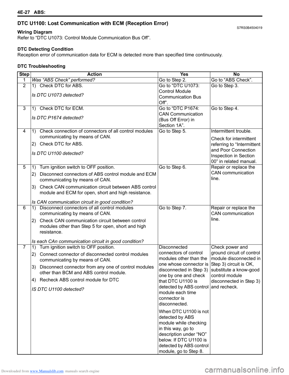
DTC Troubleshooting Step Action Yes No 1 Was “ABS Check” performed? Go to Step 2. Go to “ABS Check”.
2 1) Check DTC for ABS.
Is DTC U1073 detected? Go to “DTC U1073:
Control Module
Communication Bus
Off”.Go to Step 3.
3 1) Check DTC for ECM. Is DTC P1674 detected? Go to “DTC P1674:
CAN Communication
(Bus Off Error) in
Section 1A”.Go to Step 4.
4 1) Check connection of connectors of all control modules communicating by means of CAN.
2) Check DTC for ABS.
Is DTC U1100 detected? Go to Step 5. Intermittent trouble.
Check for intermittent
referring to “Intermittent
and Poor Connection
Inspection in Section
00” in related manual.
5 1) Turn ignition switch to OFF position.
2) Disconnect connectors of ABS control module and ECM
communicating by means of CAN.
3) Check CAN communication circuit between ABS control module and ECM for open, short and high resistance.
Is CAN communication circuit in good condition? Go to Step 6. Repair or replace the
CAN communication
line.
6 1) Disconnect connectors of all control modules communicating by means of CAN.
2) Check CAN communication circuit between control modules other than Step 5 for open, short and high
resistance.
Is each CAn communication circuit in good condition? Go to Step 7. Repair or replace the
CAN communication
line.
7 1) Turn ignition switch to OFF position. 2) Connect connector of disconnected control modules communicating by means of CAN.
3) Disconnect connector from any one of control modules other than BCM and ABS control module.
4) Recheck ABS contro l module for DTC
IS DTC U1100 detected? Disconnected
connectors of control
modules other than the
one whose connector is
disconnected in Step 3)
one by one and check
that DTC U1100 is
detected by ABS control
module each time
connector is
disconnected.
When DTC U1100 is not
detected by ABS
module while checking
in this way, go to
description under “NO”
below. If DTC U1100 is
detected by ABS control
module, go to Step 8.Check power and
ground circuit of control
module disconnected in
Step 3) circuit is OK,
substitute a know-good
control module
disconnected in Step 3)
and recheck.
Page 567 of 1496
Downloaded from www.Manualslib.com manuals search engine ABS: 4E-28
Repair Instructions
ABS Hydraulic Unit Operation CheckS7RS0B4506001
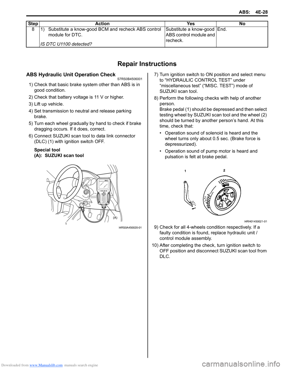
1) Check that basic brake system other than ABS is in good condition.
2) Check that battery voltage is 11 V or higher.
3) Lift up vehicle.
4) Set transmission to neutral and release parking brake.
5) Turn each wheel gradually by hand to check if brake dragging occurs. If it does, correct.
6) Connect SUZUKI scan tool to data link connector (DLC) (1) with ignition switch OFF.
Special tool
(A): SUZUKI scan tool 7) Turn ignition switch to ON position and select menu
to “HYDRAULIC CONTROL TEST” under
“miscellaneous test” (“MISC. TEST”) mode of
SUZUKI scan tool.
8) Perform the following checks with help of another person.
Brake pedal (1) should be depressed and then select
testing wheel by SUZUKI scan tool and the wheel (2)
should be turned by another person’s hand. At this
time, check that:
• Operation sound of solenoid is heard and the wheel turns only about 0.5 sec. (Brake force is
depressurized).
• Operation sound of pump motor is heard and pulsation is felt at brake pedal.
9) Check for all 4-wheels co ndition respectively. If a
faulty condition is found, replace hydraulic unit /
control module assembly.
10) After completing the check, turn ignition switch to OFF position and disconnect SUZUKI scan tool from
DLC.
8 1) Substitute a know-good BCM and recheck ABS control
module for DTC.
IS DTC U1100 detected? Substitute a know-good
ABS control module and
recheck.
End.
Step Action Yes No
1 (A)I4RS0A450020-01
I4RH01450021-01
Page 570 of 1496
Downloaded from www.Manualslib.com manuals search engine 4E-31 ABS:
2) Bleed air from brake system referring to “Air Bleeding of Brake System in Section 4A”.
3) Check each installed part for fluid leakage and perform “ABS Hydraulic Un it Operation Check”.
NOTE
For new ABS hydraulic unit / control module
assembly, if “ABS Hydraulic Unit Operation
Check” has not been performed, ABS
warning light may flash when ignition switch
is turned ON position.
Accordingly preform “ABS Hydraulic Unit
Operation Check” to stop flashing of ABS
warning light.
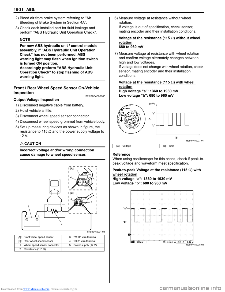
Front / Rear Wheel Speed Sensor On-Vehicle
Inspection
S7RS0B4506005
Output Voltage Inspection
1) Disconnect negative cable from battery.
2) Hoist vehicle a little.
3) Disconnect wheel speed sensor connector.
4) Disconnect wheel speed grommet from vehicle body.
5) Set up measuring devices as shown in figure, the resistance to 115 Ω and the power supply voltage to
12 V.
CAUTION!
Incorrect voltage and/or wrong connection
cause damage to wheel speed sensor.
6) Measure voltage at resistance without wheel rotation.
If voltage is out of specification, check sensor,
mating encoder and their installation conditions.
Voltage at the resistance (115
Ω) without wheel
rotation
680 to 960 mV
7) Measure voltage at resistance with wheel rotation and confirm voltage alternately changes between
high and low voltages.
If voltage does not change with wheel rotation, check
sensor, mating encoder and their installation
conditions.
Voltage at the resistance (115
Ω) with wheel
rotation
High voltage “a”: 1360 to 1930 mV
Low voltage “b”: 680 to 960 mV
Reference
When using oscilloscope for this check, check if peak-to-
peak voltage and waveform meet specification.
Peak-to-peak Voltage at the resistance (115
Ω) with
wheel rotation
High voltage “a”: 1360 to 1930 mV
Low voltage “b”: 680 to 960 mV
[A]: Front wheel speed sensor 3. “WHT” wire terminal
[B]: Rear wheel speed sensor 4. “BLK” wire terminal
1. Wheel speed sensor connector 5. Power supply (12 V)
2. Resistance (115 Ω )
V
2
5
41
3
43
1
[A]
[B]
I6RS0B460031-02
[A]: Voltage [B]: Time
I5JB0A450027-01
I5JB0A450028-02
Page 588 of 1496
Downloaded from www.Manualslib.com manuals search engine 4F-14 Electronic Stability Program:
Step 2: Driving Test
Test the vehicle at 40 km/h for more than a minute including left and right turns and check if any trouble symptom
(such as ESP ® warning lamp and/or ABS warning lamp) exists.
If the malfunction DTC is confirmed at ignition switch ON, proceed to Step 3.
If the malfunction DTC is not confirmed at ignition switch ON, proceed to Step 6.
Step 3: DTC Check
Recheck DTC referring to “DTC Check”.
Step 4: ESP ® Check
According to ESP ® Check for the DTC confirmation in Step 3, locate the cause of the trouble, namely in a sensor,
switch, wire harness, connector, actuator assembly or other part and repair or replace faulty parts.
Step 5: Brakes Diagnosis
Check the parts or system suspected as a possible cause referring to “Brakes Symptom Diagnosis in Section 4A” and
based on symptoms appearing on the vehicle (symptom obtain ed through Steps 1 and 2 and repair or replace faulty
parts, if any).
Step 6: Intermittent Problem Check
Check parts where an intermittent trouble is easy to occur (e.g., wire harness, connector, etc.), referring to
“Intermittent and Poor Connection Inspection in Section 00” and related circuit of trouble code recorded in Step 1 to 3.
Step 7: Final Confirmation Test
Confirm that the problem symptom has gone and the ESP ® is free from any abnormal conditions. If what has been
repaired is related to the malfunction DTC, clear the DTC once referrin g to “DTC Clearance” and perform test driving
and confirm that no DTC is indicated.
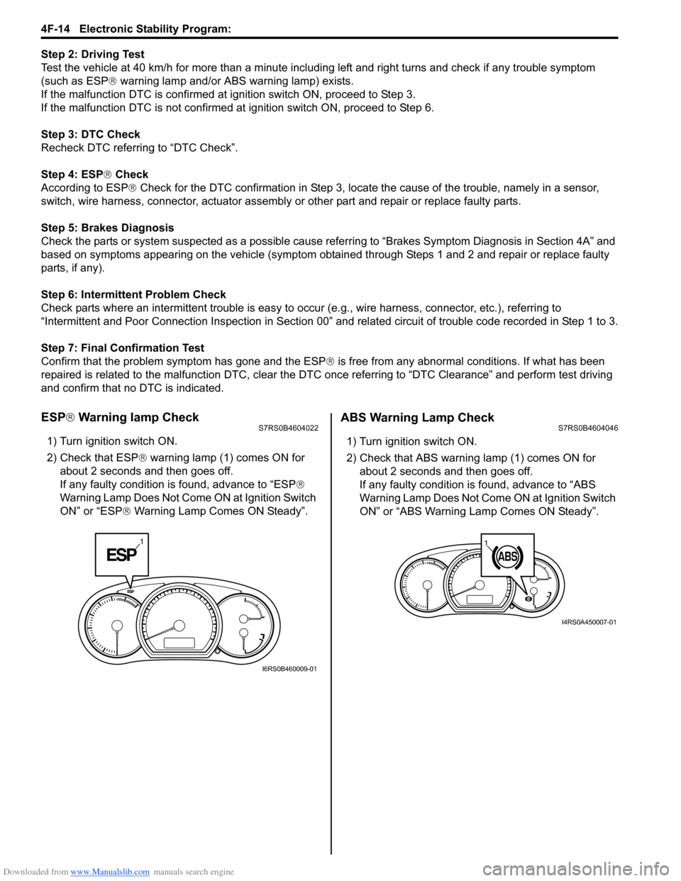
ESP ® Warning lamp CheckS7RS0B4604022
1) Turn ignition switch ON.
2) Check that ESP ® warning lamp (1) comes ON for
about 2 seconds and then goes off.
If any faulty condition is found, advance to “ESP ®
Warning Lamp Does Not Come ON at Ignition Switch
ON” or “ESP ® Warning Lamp Comes ON Steady”.
ABS Warning Lamp CheckS7RS0B4604046
1) Turn ignition switch ON.
2) Check that ABS warning lamp (1) comes ON for
about 2 seconds and then goes off.
If any faulty condition is found, advance to “ABS
Warning Lamp Does Not Come ON at Ignition Switch
ON” or “ABS Warning Lamp Comes ON Steady”.
1
I6RS0B460009-01
11
I4RS0A450007-01
Page 594 of 1496
Downloaded from www.Manualslib.com manuals search engine 4F-20 Electronic Stability Program:
NOTE
•�{: Activated
• X: Deactivated
• *1: If two or more wheel speed sensor are defective, ABS warning lamp, EBD warning lamp and ESP ® warning lamp are lit and all the control functions are deactivated. If one wheel speed sensor is
defective, ABS warning lamp and ESP ® warning lamp are lit and ABS and TCS / stability control are
deactivated.
• *2: ESP ® OFF mode is cancelled and all control functions are activated.
• *3: EBD control function is activated only if po wer supply circuit is little low voltage malfunction.
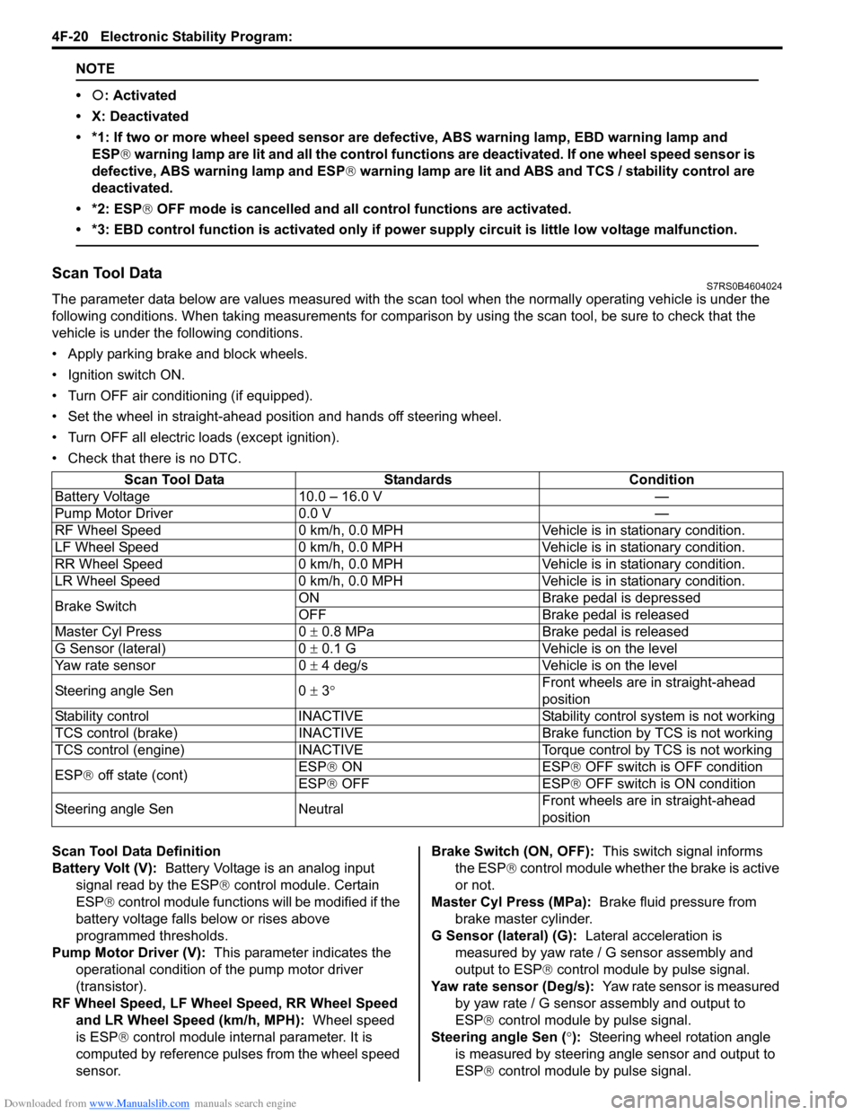
Scan Tool DataS7RS0B4604024
The parameter data below are values measured with the scan tool when the normally operating vehicle is under the
following conditions. When taking measurements for comparis on by using the scan tool, be sure to check that the
vehicle is under the following conditions.
• Apply parking brake and block wheels.
• Ignition switch ON.
• Turn OFF air conditioning (if equipped).
• Set the wheel in straight-ahead position and hands off steering wheel.
• Turn OFF all electric loads (except ignition).
• Check that there is no DTC.
Scan Tool Data Definition
Battery Volt (V): Battery Voltage is an analog input
signal read by the ESP ® control module. Certain
ESP ® control module functions will be modified if the
battery voltage falls below or rises above
programmed thresholds.
Pump Motor Driver (V): This parameter indicates the
operational condition of the pump motor driver
(transistor).
RF Wheel Speed, LF Wheel Speed, RR Wheel Speed and LR Wheel Speed (km/h, MPH): Wheel speed
is ESP ® control module internal parameter. It is
computed by reference puls es from the wheel speed
sensor. Brake Switch (ON, OFF):
This switch signal informs
the ESP ® control module whether the brake is active
or not.
Master Cyl Press (MPa): Brake fluid pressure from
brake master cylinder.
G Sensor (lateral) (G): Lateral acceleration is
measured by yaw rate / G sensor assembly and
output to ESP ® control module by pulse signal.
Yaw rate sensor (Deg/s): Yaw rate sensor is measured
by yaw rate / G sensor assembly and output to
ESP® control module by pulse signal.
Steering angle Sen ( °): Steering wheel rotation angle
is measured by steering angle sensor and output to
ESP® control module by pulse signal.
Scan Tool Data Standards Condition
Battery Voltage 10.0 – 16.0 V —
Pump Motor Driver 0.0 V —
RF Wheel Speed 0 km/h, 0.0 MPH Veh icle is in stationary condition.
LF Wheel Speed 0 km/h, 0.0 MPH Veh icle is in stationary condition.
RR Wheel Speed 0 km/h, 0.0 MPH Vehic le is in stationary condition.
LR Wheel Speed 0 km/h, 0.0 MPH Veh icle is in stationary condition.
Brake Switch ON Brake pedal is depressed
OFF Brake pedal is released
Master Cyl Press 0 ± 0.8 MPa Brake pedal is released
G Sensor (lateral) 0 ± 0.1 G Vehicle is on the level
Yaw rate sensor 0 ± 4 deg/s Vehicle is on the level
Steering angle Sen 0 ± 3 ° Front wheels are in straight-ahead
position
Stability control INACTIVE Stability control system is not working
TCS control (brake) INACTIVE Brake function by TCS is not working
TCS control (engine) INACTIVE Torque control by TCS is not working
ESP ® off state (cont) ESP®
ON ESP
® OF
F switch is OFF condition
ESP® OFF ESP ® OFF switch is ON condition
Steering angle Sen Neutral Front wheels are in straight-ahead
position
Page 596 of 1496
Downloaded from www.Manualslib.com manuals search engine 4F-22 Electronic Stability Program:
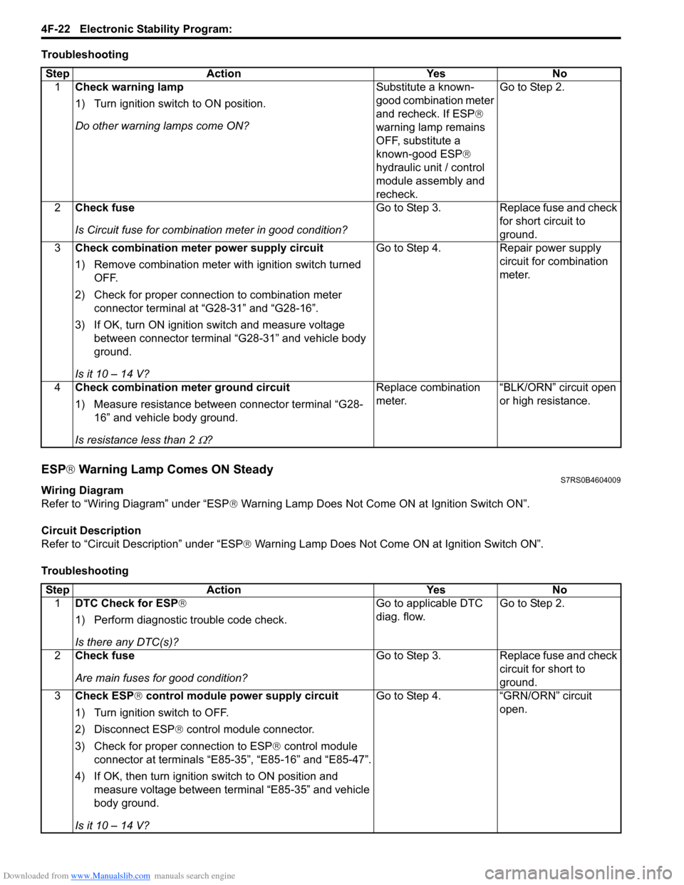
Troubleshooting
ESP® Warning Lamp Comes ON SteadyS7RS0B4604009
Wiring Diagram
Refer to “Wiring Diagram” under “ESP ® Warning Lamp Does Not Come ON at Ignition Switch ON”.
Circuit Description
Refer to “Circuit Description” under “ESP ® Warning Lamp Does Not Come ON at Ignition Switch ON”.
Troubleshooting Step Action Yes No
1 Check warning lamp
1) Turn ignition switch to ON position.
Do other warning lamps come ON? Substitute a known-
good combination meter
and recheck. If ESP®
warning lamp remains
OFF, substitute a
known-good ESP ®
hydraulic unit / control
module assembly and
recheck. Go to Step 2.
2 Check fuse
Is Circuit fuse fo r combination meter in good condition? Go to Step 3. Replace fuse and check
for short circuit to
ground.
3 Check combination meter power supply circuit
1) Remove combination meter wit h ignition switch turned
OFF.
2) Check for proper connection to combination meter connector terminal at “G28-31” and “G28-16”.
3) If OK, turn ON ignition switch and measure voltage between connector terminal “G28-31” and vehicle body
ground.
Is it 10 – 14 V? Go to Step 4. Repair power supply
circuit for combination
meter.
4 Check combination me ter ground circuit
1) Measure resistance between connector terminal “G28- 16” and vehicle body ground.
Is resistance less than 2
Ω? Replace combination
meter.
“BLK/ORN” circuit open
or high resistance.
Step
Action YesNo
1 DTC Check for ESP ®
1) Perform diagnostic trouble code check.
Is there any DTC(s)? Go to applicable DTC
diag. flow.
Go to Step 2.
2 Check fuse
Are main fuses for good condition? Go to Step 3.
Replace fuse and check
circuit for short to
ground.
3 Check ESP ® control module power supply circuit
1) Turn ignition switch to OFF.
2) Disconnect ESP ® control module connector.
3) Check for proper connection to ESP ® control module
connector at terminals “E85-35”, “E85-16” and “E85-47”.
4) If OK, then turn ignition switch to ON position and measure voltage between terminal “E85-35” and vehicle
body ground.
Is it 10 – 14 V? Go to Step 4.
“GRN/ORN” circuit
open.
Page 597 of 1496
Downloaded from www.Manualslib.com manuals search engine Electronic Stability Program: 4F-23
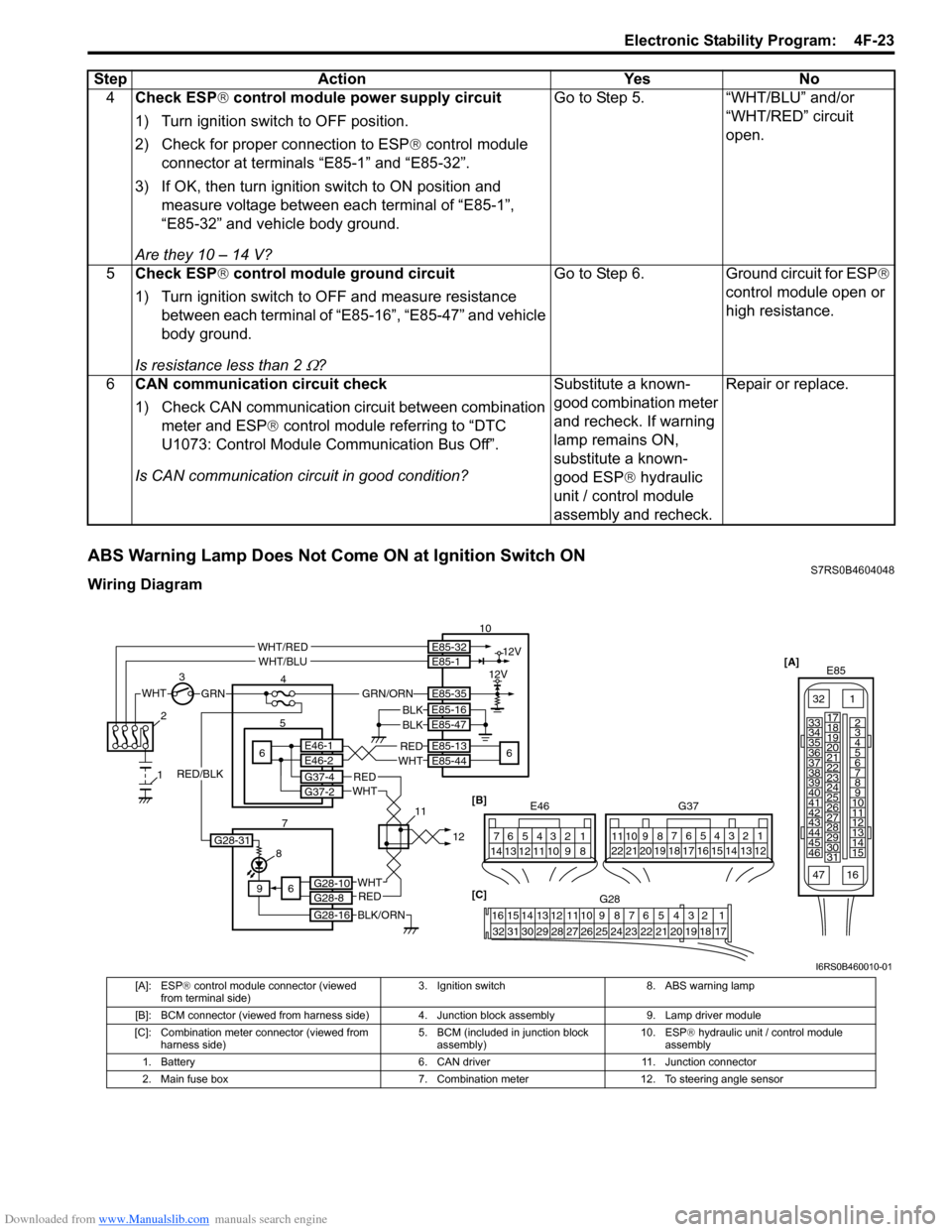
ABS Warning Lamp Does Not Come ON at Ignition Switch ONS7RS0B4604048
Wiring Diagram4
Check ESP ® control module power supply circuit
1) Turn ignition switch to OFF position.
2) Check for proper connection to ESP ® control module
connector at terminals “E85-1” and “E85-32”.
3) If OK, then turn ignition switch to ON position and measure voltage between each terminal of “E85-1”,
“E85-32” and vehicle body ground.
Are they 10 – 14 V? Go to Step 5. “WHT/BLU” and/or
“WHT/RED” circuit
open.
5 Check ESP ® control module ground circuit
1) Turn ignition switch to OFF and measure resistance between each terminal of “E85-16”, “E85-47” and vehicle
body ground.
Is resistance less than 2
Ω? Go to Step 6.
Ground circuit for ESP®
control module open or
high resistance.
6 CAN communication circuit check
1) Check CAN communication circuit between combination
meter and ESP ® control module referring to “DTC
U1073: Control Module Communication Bus Off”.
Is CAN communication circuit in good condition? Substitute a known-
good combination meter
and recheck. If warning
lamp remains ON,
substitute a known-
good ESP
® hydraulic
unit / control module
assembly and recheck. Repair or replace.
Step
Action YesNo
[A]
E85
161
15
2
3
4
5
6
7
8
9
10
11
12
13
14
17
18
19
20
21
22
23
24
25
26
27
28
29
30
31
3233
34
35
36
37
38
39
40
41
42
43
44
45
46
47
WHTGRN
3
E85-13
E85-44REDWHT6 5E46-1E46-2
4 10
6
E85-16
E85-47BLKBLK
8
9
BLK/ORN
REDWHT
REDWHT
G37-4G37-2
G28-10G28-8
G28-16
12V
12VE85-32E85-1
E85-35
WHT/REDWHT/BLU
GRN/ORN
6
2
1
7 1112[B]
G37
E46124
53
67
891011121314124
53
67
891011
1213141516171819202122
[C] G28
12345678910111213141516
17181920212223242526272829303132
G28-31
RED/BLK
I6RS0B460010-01
[A]: ESP ® control module connector (viewed
from terminal side) 3. Ignition switch 8. ABS warning lamp
[B]: BCM connector (viewed from harness side) 4. Junction block assembly 9. Lamp driver module
[C]: Combination meter connector (viewed from harness side) 5. BCM (included in junction block
assembly) 10. ESP
® hydraulic unit / control module
assembly
1. Battery 6. CAN driver11. Junction connector
2. Main fuse box 7. Combination meter12. To steering angle sensor
Page 599 of 1496
Downloaded from www.Manualslib.com manuals search engine Electronic Stability Program: 4F-25
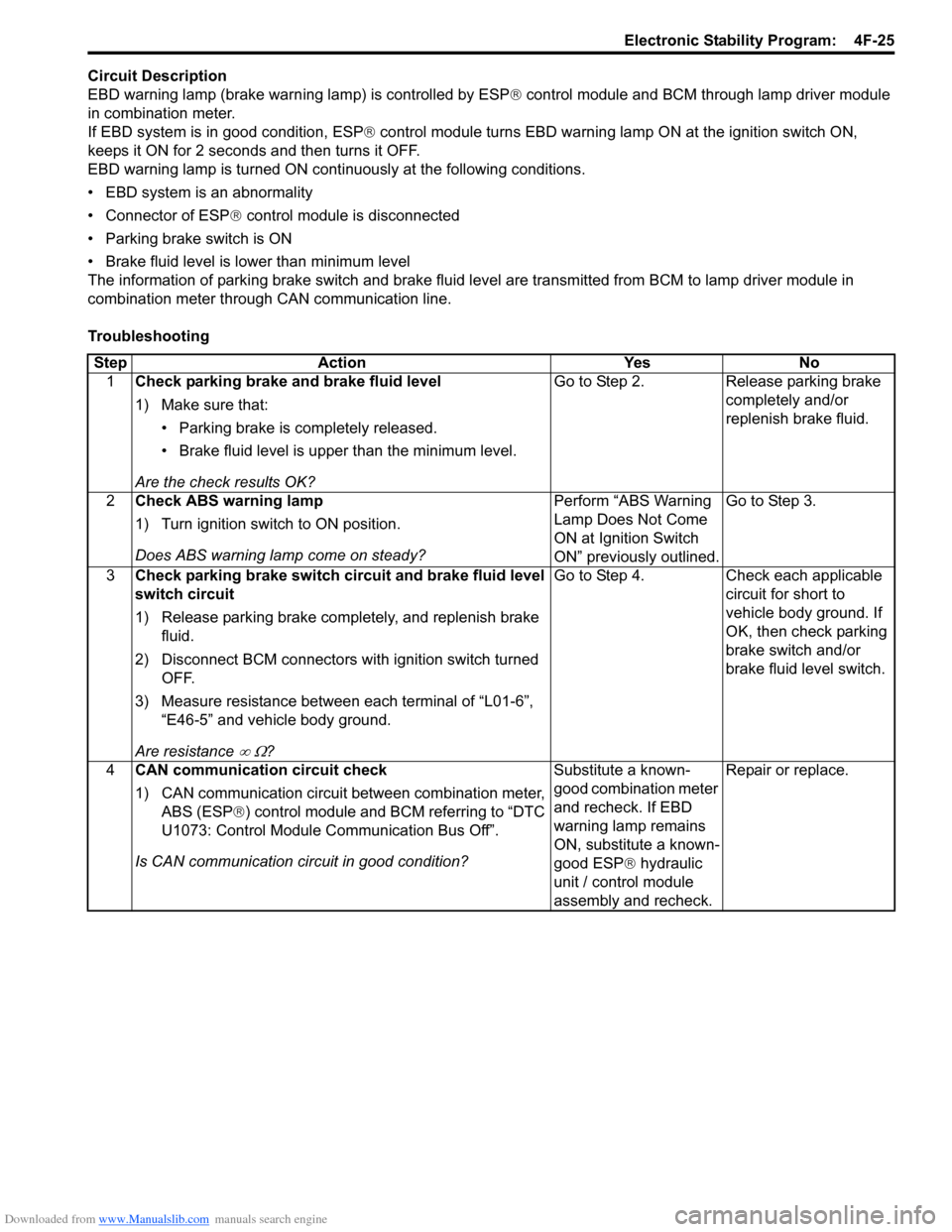
Circuit Description
EBD warning lamp (brake warning lamp) is controlled by ESP® control module and BCM through lamp driver module
in combination meter.
If EBD system is in good condition, ESP ® control module turns EBD warning lamp ON at the ignition switch ON,
keeps it ON for 2 seconds and then turns it OFF.
EBD warning lamp is turned ON cont inuously at the following conditions.
• EBD system is an abnormality
• Connector of ESP ® control module is disconnected
• Parking brake switch is ON
• Brake fluid level is lower than minimum level
The information of parking brake switch and brake fluid leve l are transmitted from BCM to lamp driver module in
combination meter through CAN communication line.
Troubleshooting
Step Action Yes No 1 Check parking brake and brake fluid level
1) Make sure that:
• Parking brake is completely released.
• Brake fluid level is upper than the minimum level.
Are the check results OK? Go to Step 2. Release parking brake
completely and/or
replenish brake fluid.
2 Check ABS warning lamp
1) Turn ignition switch to ON position.
Does ABS warning lamp come on steady? Perform “ABS Warning
Lamp Does Not Come
ON at Ignition Switch
ON” previously outlined.Go to Step 3.
3 Check parking brake switch circuit and brake fluid level
switch circuit
1) Release parking brake completely, and replenish brake
fluid.
2) Disconnect BCM connectors with ignition switch turned OFF.
3) Measure resistance between each terminal of “L01-6”, “E46-5” and vehicle body ground.
Are resistance
∞ Ω? Go to Step 4. Check each applicable
circuit for short to
vehicle body ground. If
OK, then check parking
brake switch and/or
brake fluid level switch.
4 CAN communication circuit check
1) CAN communication circuit between combination meter,
ABS (ESP® ) control module and BCM referring to “DTC
U1073: Control Module Communication Bus Off”.
Is CAN communication circuit in good condition? Substitute a known-
good combination meter
and recheck. If EBD
warning lamp remains
ON, substitute a known-
good ESP
® hydraulic
unit / control module
assembly and recheck. Repair or replace.
Page 601 of 1496
Downloaded from www.Manualslib.com manuals search engine Electronic Stability Program: 4F-27
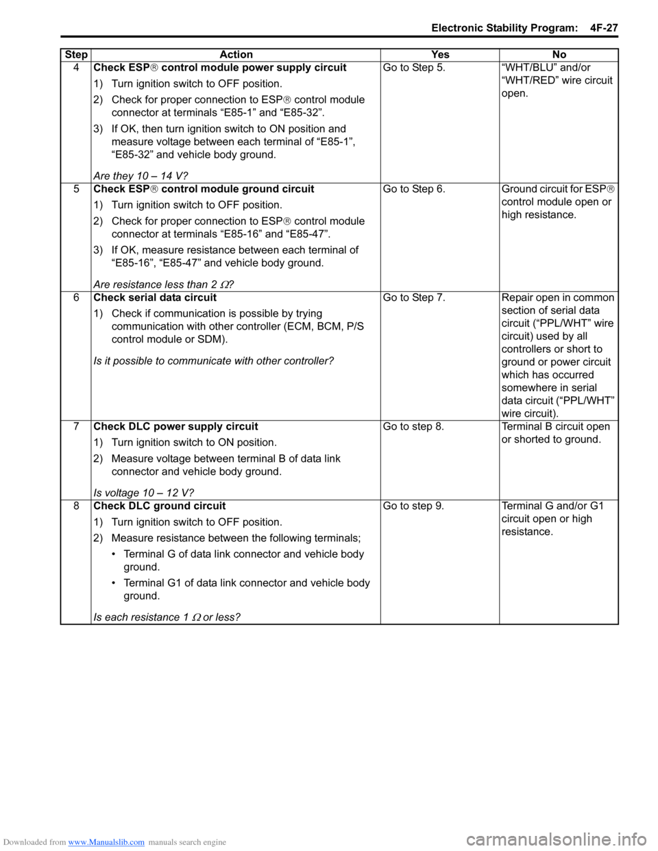
4Check ESP ® control module power supply circuit
1) Turn ignition switch to OFF position.
2) Check for proper connection to ESP ® control module
connector at terminals “E85-1” and “E85-32”.
3) If OK, then turn ignition switch to ON position and measure voltage between each terminal of “E85-1”,
“E85-32” and vehicle body ground.
Are they 10 – 14 V? Go to Step 5. “WHT/BLU” and/or
“WHT/RED” wire circuit
open.
5 Check ESP ® control module ground circuit
1) Turn ignition switch to OFF position.
2) Check for proper connection to ESP ® control module
connector at terminals “E85-16” and “E85-47”.
3) If OK, measure resistance between each terminal of “E85-16”, “E85-47” and vehicle body ground.
Are resistance less than 2
Ω? Go to Step 6. Ground circuit for ESP
®
control module open or
high resistance.
6 Check serial data circuit
1) Check if communication is possible by trying
communication with other c ontroller (ECM, BCM, P/S
control module or SDM).
Is it possible to commun icate with other controller? Go to Step 7. Repair open in common
section of serial data
circuit (“PPL/WHT” wire
circuit) used by all
controllers or short to
ground or power circuit
which has occurred
somewhere in serial
data circuit (“PPL/WHT”
wire circuit).
7 Check DLC power supply circuit
1) Turn ignition switch to ON position.
2) Measure voltage between terminal B of data link
connector and vehicle body ground.
Is voltage 10 – 12 V? Go to step 8. Terminal B circuit open
or shorted to ground.
8 Check DLC ground circuit
1) Turn ignition switch to OFF position.
2) Measure resistance between the following terminals;
• Terminal G of data link connector and vehicle body ground.
• Terminal G1 of data link connector and vehicle body ground.
Is each resistance 1
Ω or less? Go to step 9. Terminal G and/or G1
circuit open or high
resistance.
Step Action Yes No