4e-1 SUZUKI SWIFT 2008 2.G Service User Guide
[x] Cancel search | Manufacturer: SUZUKI, Model Year: 2008, Model line: SWIFT, Model: SUZUKI SWIFT 2008 2.GPages: 1496, PDF Size: 34.44 MB
Page 556 of 1496
Downloaded from www.Manualslib.com manuals search engine 4E-17 ABS:
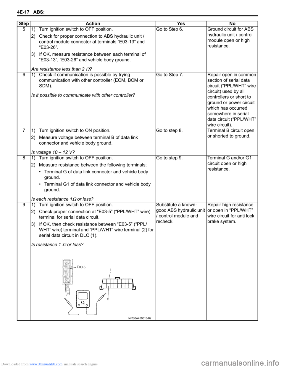
5 1) Turn ignition switch to OFF position.2) Check for proper connection to ABS hydraulic unit / control module connector at terminals “E03-13” and
“E03-26”.
3) If OK, measure resistance between each terminal of “E03-13”, “E03-26” and vehicle body ground.
Are resistance less than 2
Ω? Go to Step 6. Ground circuit for ABS
hydraulic unit / control
module open or high
resistance.
6 1) Check if communication is possible by trying communication with other controller (ECM, BCM or
SDM).
Is it possible to commun icate with other controller? Go to Step 7. Repair open in common
section of serial data
circuit (“PPL/WHT” wire
circuit) used by all
controllers or short to
ground or power circuit
which has occurred
somewhere in serial
data circuit (“PPL/WHT”
wire circuit).
7 1) Turn ignition switch to ON position.
2) Measure voltage between terminal B of data link connector and vehicle body ground.
Is voltage 10 – 12 V? Go to step 8. Terminal B circuit open
or shorted to ground.
8 1) Turn ignition switch to OFF position. 2) Measure resistance between the following terminals;• Terminal G of data link connector and vehicle body ground.
• Terminal G1 of data link connector and vehicle body ground.
Is each resistance 1
Ω or less? Go to step 9. Terminal G and/or G1
circuit open or high
resistance.
9 1) Turn ignition switch to OFF position. 2) Check proper connection at “E03-5” (“PPL/WHT” wire) terminal for serial data circuit.
3) If OK, then check resistance between “E03-5” (“PPL/ WHT” wire) terminal and “PPL/WHT” wire terminal (2) for
serial data circuit in DLC (1).
Is resistance 1
Ω or less? Substitute a known-
good ABS hydraulic unit
/ control module and
recheck.
Repair high resistance
or open in “PPL/WHT”
wire circuit for anti lock
brake system.
Step Action Yes No
I4RS0A450013-02
Page 557 of 1496
Downloaded from www.Manualslib.com manuals search engine ABS: 4E-18
DTC C1021, C1022 / C1025, C1026 / C1031, C1032 / C1035, C1036: Right-Front / Left-Front / Right-
Rear / Left-Rear Wheel Speed Sensor Circuit or Sensor Ring
S7RS0B4504012
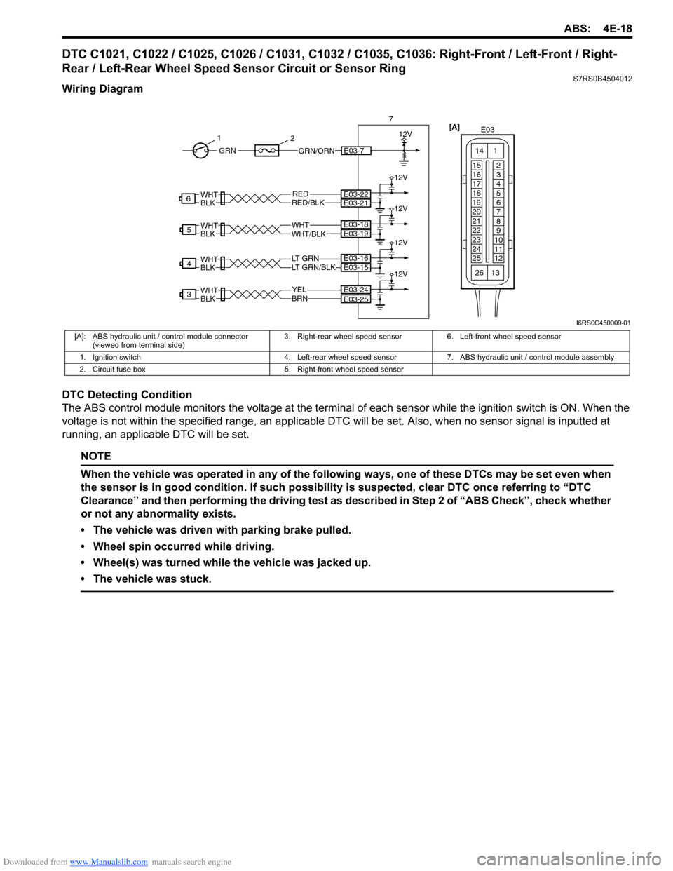
Wiring Diagram
DTC Detecting Condition
The ABS control module monitors the voltage at the terminal of each sensor while the ignition swit ch is ON. When the
voltage is not within the specified range, an applicable DTC will be set. Also, when no sensor signal is inputted at
running, an applicable DTC will be set.
NOTE
When the vehicle was operated in any of the following ways, one of these DTCs may be set even when
the sensor is in good condition. If such possibility is suspected, clear DTC once referring to “DTC
Clearance” and then performing the driving test as described in Step 2 of “ABS Check”, check whether
or not any abnormality exists.
• The vehicle was driven with parking brake pulled.
• Wheel spin occurred while driving.
• Wheel(s) was turned while the vehicle was jacked up.
• The vehicle was stuck.
YELBRN
3E03-24
LT GRN/BLKLT GRN
4
WHTWHT/BLK
5
RED
WHTBLK
WHTBLK
WHTBLK
WHTBLKRED/BLK
6
E03-25
E03-15E03-16
E03-19E03-18
E03-22E03-21
12V
12V
12V
12V
12V
7
GRN/ORNE03-7GRN
1
2
[A]
E03
15
16
17
18
19
20
21
22
23
24
25 2
3
4
5
6
7
8
9
10
11
12
1
13
14
26
I6RS0C450009-01
[A]: ABS hydraulic unit / control module connector
(viewed from terminal side) 3. Right-rear wheel speed sensor 6. Left-front wheel speed sensor
1. Ignition switch 4. Left-rear wheel speed sensor 7. ABS hydraulic unit / control module assembly
2. Circuit fuse box 5. Right-front wheel speed sensor
Page 558 of 1496
Downloaded from www.Manualslib.com manuals search engine 4E-19 ABS:
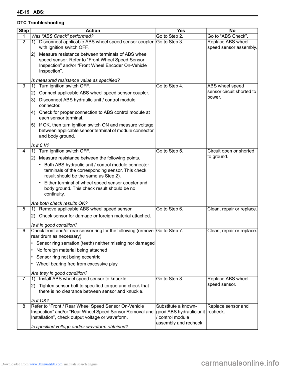
DTC TroubleshootingStep Action Yes No 1 Was “ABS Check” performed? Go to Step 2. Go to “ABS Check”.
2 1) Disconnect applicable ABS wheel speed sensor coupler with ignition switch OFF.
2) Measure resistance betw een terminals of ABS wheel
speed sensor. Refer to “Front Wheel Speed Sensor
Inspection” and/or “Front Wheel Encoder On-Vehicle
Inspection”.
Is measured resistance value as specified? Go to Step 3. Replace ABS wheel
speed sensor assembly.
3 1) Turn ignition switch OFF. 2) Connect applicable ABS wh eel speed sensor coupler.
3) Disconnect ABS hydraulic unit / control module connector.
4) Check for proper connection to ABS control module at each sensor terminal.
5) If OK, then turn ignition switch ON and measure voltage between applicable sensor terminal of module connector
and body ground.
Is it 0 V? Go to Step 4. ABS wheel speed
sensor circuit shorted to
power.
4 1) Turn ignition switch OFF. 2) Measure resistance between the following points.• Both ABS hydraulic unit / control module connector terminals of the correspo nding sensor. This check
result should be the same as Step 2).
• Either terminal of wheel speed sensor coupler and body ground. This check result should be no
continuity.
Are both check results OK? Go to Step 5. Circuit open or shorted
to ground.
5 1) Remove applicable ABS wheel speed sensor. 2) Check sensor for damage or foreign material attached.
Is it in good condition? Go to Step 6. Clean, repair or replace.
6 Check front and/or rear sensor ring for the following (remove rear drum as necessary):
• Sensor ring serration (teeth) neither missing nor damaged
• No foreign material being attached
• Sensor ring not being eccentric
• Wheel bearing free from excessive play
Are they in good condition? Go to Step 7. Clean, repair or replace.
7 1) Install ABS wheel speed sensor to knuckle. 2) Tighten sensor bolt to specified torque and check that there is no clearance between sensor and knuckle.
Is it OK? Go to Step 8. Replace ABS wheel
speed sensor.
8 Refer to “Front / Rear Wheel Speed Sensor On-Vehicle Inspection” and/or “Rear Wheel Speed Sensor Removal and
Installation”, check output voltage or waveform.
Is specified voltage and/or waveform obtained? Substitute a known-
good ABS hydraulic unit
/ control module
assembly and recheck.
Replace sensor and
recheck.