flat tire SUZUKI SWIFT 2008 2.G Service User Guide
[x] Cancel search | Manufacturer: SUZUKI, Model Year: 2008, Model line: SWIFT, Model: SUZUKI SWIFT 2008 2.GPages: 1496, PDF Size: 34.44 MB
Page 471 of 1496
Downloaded from www.Manualslib.com manuals search engine Wheels and Tires: 2D-4
Radial Tire Waddle DescriptionS7RS0B2401005
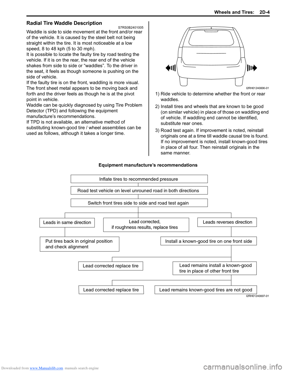
Waddle is side to side movement at the front and/or rear
of the vehicle. It is caused by the steel belt not being
straight within the tire. It is most noticeable at a low
speed, 8 to 48 kph (5 to 30 mph).
It is possible to locate the f aulty tire by road testing the
vehicle. If it is on the rear , the rear end of the vehicle
shakes from side to side or “waddles”. To the driver in
the seat, it feels as though someone is pushing on the
side of vehicle.
If the faulty tire is on the front, waddling is more visual.
The front sheet metal appears to be moving back and
forth and the driver feels as though he is at the pivot
point in vehicle.
Waddle can be quickly diagnosed by using Tire Problem
Detector (TPD) and following the equipment
manufacture’s recommendations.
If TPD is not available, an alternative method of
substituting known-good tire / wheel assemblies can be
used as follows, although it takes a longer time. 1) Ride vehicle to determine whether the front or rear
waddles.
2) Install tires and wheels that are known to be good (on similar vehicle) in place of those on waddling end
of vehicle. If waddling end cannot be identified,
substitute rear ones.
3) Road test again. If improvement is noted, reinstall originals one at a time till w addle causal tire is found.
If no improvement is noted, install known-good tires
in place of all four. Then reinstall originals in the
same manner.
Equipment manufacture’s recommendations
I2RH01240006-01
Inflate tires to recommended pressure
Road test vehicle on level unrouned road in both directions
Switch front tires side to side and road test again
Lead corrected,
if roughness results, replace tiresLeads in same directionLeads reverses direction
Put tires back in original position
and check alignmentInstall a known-good tire on one front side
Lead remains install a known-good
tire in place of other front tire
Lead remains known-good tires are not goodLead corrected replace tire
Lead corrected replace tire
I2RH01240007-01
Page 475 of 1496
Downloaded from www.Manualslib.com manuals search engine Wheels and Tires: 2D-8
Tire Mounting and DismountingS7RS0B2406004
CAUTION!
When installing tire which has arrow
indicating tire rotation direction to wheel,
make sure that this tire rotation direction is
same as actual tire rotation direction when
vehicle is moving forward. Otherwise, it is
not possible to install wheel with tire to
vehicle in specified direction.
Use a tire changing machine to mount or dismount tires.
Follow equipment manufacturer’s instructions. Do not
use hand tools or tire irons al one to change tires as they
may damage tire beads or wheel rim.
Rim bead seats should be cleaned with a wire brush or
coarse steel wool to remove lubricants, old rubber and
light rust. Before mounting or dismounting a tire, bead
area should be well lubricated with approved tire
lubricant.
After mounting, inflate to specified pressure shown on
tire placard so that beads are completely seated.
WARNING!
Do not stand over tire when inflating. Bead
may break when bead snaps over rim’s safety
hump and cause serious personal injury.
Do not exceed 330 kpa (47.9 psi) pressure
when inflating. If 330 kpa (47.9 psi) pressure
will not seat beads, deflate, re-lubricate and
reinflate.
Over inflation may cause bead to break and
cause serious personal injury.
Install valve core and inflate to proper pressure.
Tire RepairS7RS0B2406005
There are many different materials and techniques on
the market to repair tires. As not all of these work on all
types of tires, tire manufacturers have published detailed
instructions on how and when to repair tires. These
instructions can be obtained from each tire
manufacturer.
Tire Repair for Emergency Repaired-Tire with
Sealant
S7RS0B2406006
WARNING!
Be sure to observe “Precaution for
Emergency Flat Tire Repair Kit”. Otherwise,
your health may be ruined.
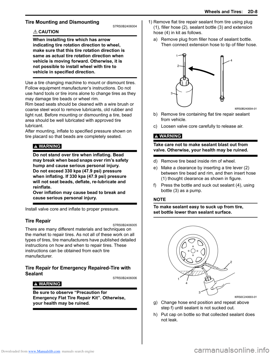
1) Remove flat tire repair sealant from tire using plug (1), filler hose (2), sealant bottle (3) and extension
hose (4) in kit as follows.
a) Remove plug from fille r hose of sealant bottle.
Then connect ext ension hose to tip of filler hose.
b) Remove tire containing flat tire repair sealant from vehicle.
c) Loosen valve core carefully to release air.
WARNING!
Take care not to make sealant blast out from
valve. Otherwise, your health may be ruined.
d) Remove tire bead inside rim of wheel.
e) Make a clearance by inserting a tire lever (2) between tire bead and rim, and then insert hose
(1) thought clearance as shown in figure.
f) Press the bottle and suck out sealant (4), using bottle (3) as a pump.
NOTE
To make sealant easy to suck up from tire,
set bottle lower than sealant surface.
g) Change hose end position and repeat above step f) until sealant is not sucked out.
h) Put cap on bottle so that collected sealant does not leak.
4
1
2
3
I6RS0B240004-01
1 4
3 2
I6RS0C240003-01
Page 476 of 1496
Downloaded from www.Manualslib.com manuals search engine 2D-9 Wheels and Tires:
2) Check tire if it can be repaired, referring to “Tire
Repair”. If it cannot be repaired, replace it with new
one.
3) Replace valve core of flat tire with new one if tire is reused after repairing.CAUTION!
Be sure to use new valve core. Otherwise, air
leak may occur due to sealant attached to
valve core.
4) Install tire to ri m of wheel, check that there is no air
leakage and adjust it to specified pressure shown on
tire placard.
Specifications
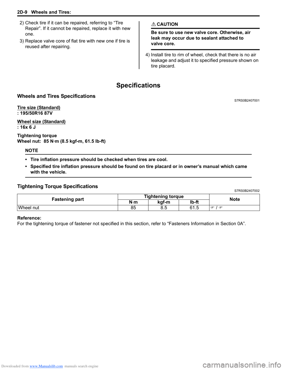
Wheels and Tires SpecificationsS7RS0B2407001
Tire size (Standard)
: 195/50R16 87V
Wheel size (Standard)
: 16x 6 J
Tightening torque
Wheel nut: 85 N·m (8.5 kgf-m, 61.5 lb-ft)
NOTE
• Tire inflation pressure should be checked when tires are cool.
• Specified tire inflation pressure should be found on tire placard or in owner’s manual which came
with the vehicle.
Tightening Torque SpecificationsS7RS0B2407002
Reference:
For the tightening torque of fastener not specified in this section, refer to “Fasteners Information in Section 0A”.
Fastening part
Tightening torque
Note
N ⋅mkgf-mlb-ft
Wheel nut 858.5 61.5 �) / �)
Page 503 of 1496
Downloaded from www.Manualslib.com manuals search engine Brake Control System and Diagnosis: 4A-5
If deterioration of rubber is evident, disassemble all
hydraulic parts and wash with alcohol. Dry these parts
with compressed air before assembly to keep alcohol out
of the system. Replace all rubber parts in the system,
including hoses. Also, when working on the brake
mechanisms, check for fluid on the linings.
If excessive fluid is found, replace the pads. If master cylinder piston seals
are satisfactory, check for
leakage or excessive heat co nditions. If leakage is not
found, drain fluid, flush with brake fluid, refill and bleed
system.
The system must be flushed if there is any doubt as to
the grade of fluid in the system or if fluid has been used
which contained parts that have been subjected to
contaminated fluid.
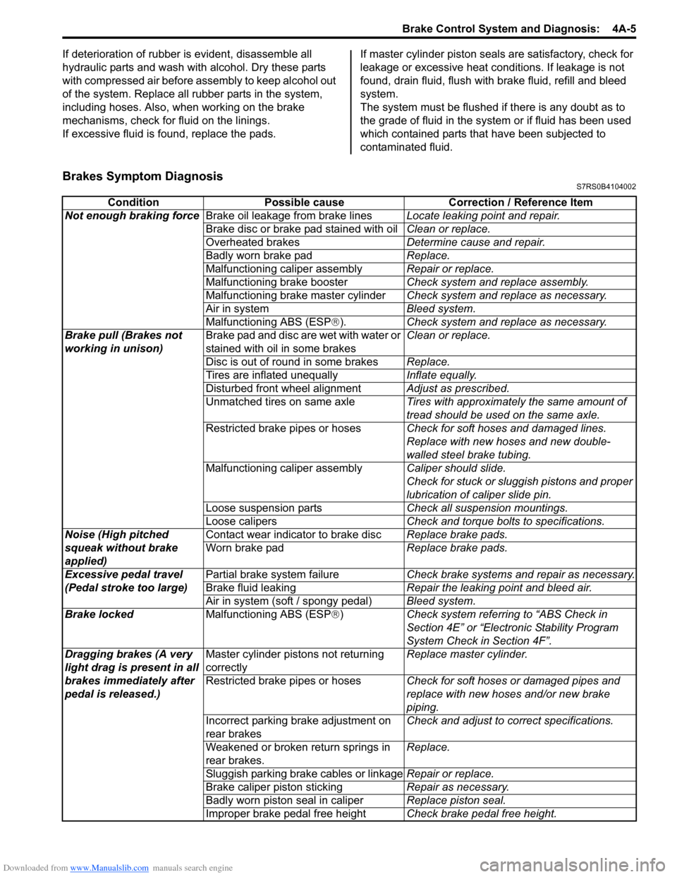
Brakes Symptom DiagnosisS7RS0B4104002
Condition Possible cause Correction / Reference Item
Not enough braking force Brake oil leakage from brake lines Locate leaking point and repair.
Brake disc or brake pad stained with oil Clean or replace.
Overheated brakes Determine cause and repair.
Badly worn brake pad Replace.
Malfunctioning caliper assembly Repair or replace.
Malfunctioning brake booster Check system and replace assembly.
Malfunctioning brake master cylinder Check system and replace as necessary.
Air in system Bleed system.
Malfunctioning ABS (ESP ®). Check system and replace as necessary.
Brake pull (Brakes not
working in unison) Brake pad and disc are wet with water or
stained with oil in some brakes Clean or replace.
Disc is out of round in some brakes Replace.
Tires are inflated unequally Inflate equally.
Disturbed front wheel alignment Adjust as prescribed.
Unmatched tires on same axle Tires with approximately the same amount of
tread should be used on the same axle.
Restricted brake pipes or hoses Check for soft hoses and damaged lines.
Replace with new hoses and new double-
walled steel brake tubing.
Malfunctioning caliper assembly Caliper should slide.
Check for stuck or sluggish pistons and proper
lubrication of caliper slide pin.
Loose suspension parts Check all suspension mountings.
Loose calipers Check and torque bolts to specifications.
Noise (High pitched
squeak without brake
applied) Contact wear indicator to brake disc
Replace brake pads.
Worn brake pad Replace brake pads.
Excessive pedal travel
(Pedal stroke too large) Partial brake system failure
Check brake systems and repair as necessary.
Brake fluid leaking Repair the leaking point and bleed air.
Air in system (soft / spongy pedal) Bleed system.
Brake locked Malfunctioning ABS (ESP®) Check system referri ng to “ABS Check in
Section 4E” or “Electronic Stability Program
System Check in Section 4F”.
Dragging brakes (A very
light drag is present in all
brakes immediately after
pedal is released.) Master cylinder pistons not returning
correctly
Replace master cylinder.
Restricted brake pipes or hoses Check for soft hoses or damaged pipes and
replace with new hoses and/or new brake
piping.
Incorrect parking brake adjustment on
rear brakes Check and adjust to correct specifications.
Weakened or broken return springs in
rear brakes. Replace.
Sluggish parking brake cables or linkage Repair or replace.
Brake caliper piston sticking Repair as necessary.
Badly worn piston seal in caliper Replace piston seal.
Improper brake pedal free height Check brake pedal free height.
Page 871 of 1496

Downloaded from www.Manualslib.com manuals search engine Steering General Diagnosis: 6A-2
Diagnostic Information and Procedures
Steering Symptom DiagnosisS7RS0B6104001
ConditionPossible cause Correction / Reference Item
Hard steering Tire not adequately inflated Inflate tires to proper pressure.
Malfunction of power steering system Check and correct.
Bind in tie-rod end ball studs or lower
ball joints Replace tie-rod end or front suspension arm.
Disturbed front wheel alignment Check and adjust front wheel alignment.
Bind in steering column Repair or replace steering column.
Rack and pinion adjustment Check and adjustment rack and pinion torque.
Too much play in steering Wheel bearings worn Replace wheel bearing.
Loose steering gear case bolts Tighten gear case bolts.
Faulty steering gear case assembly Replace steering gear case assembly.
Worn steering shaft joints Replace joint.
Worn tie-rod ends or tie-rod inside ball
joints Replace tie-rod end or tie-rod.
Worn lower ball joints Replace front suspension control arm.
Rack and pinion adjustment Check and adjustment rack and pinion torque.
Poor return ability Bind in tie-rod end ball studs Replace tie-rod end.
Bind in ball joints Replace front suspension control arm.
Bind in steering column Repair or replace steering column.
Disturbed front end alignment Check and adjust front end alignment.
Faulty steering gear case assembly Replace steering gear case assembly.
Tires not adequately inflated Adjust tire pressure.
Rack and pinion adjustment Check and adjustment rack and pinion torque.
Rack and pinion noise
(Rattle or chuckle) Loose steering gear case bolts
Tighten steering gear case bolts.
Rack and pinion adjustment Check and adjustment rack and pinion torque.
Faulty steering gear case assembly Replace steering gear case assembly.
Broken or other wise damaged wheel
bearing(s) Replace wheel bearing(s).
Wander or poor steering
stability Mismatched or uneven tires
Replace or inflate tires to proper pressure.
Loosen ball joints and tie-rod ends Replace suspension control arm or tie-rod end.
Faulty struts or mountings Replace strut or repair mounting.
Loose stabilizer bar Tighten or replace stabilizer bar or bush.
Broken or sagging springs Replace spring.
Rack and pinion adjustment Check and adjustment rack and pinion torque.
Disturbed front wheel alignment Check and adjust front wheel alignment.
Faulty steering gear case assembly Replace steering gear case assembly.
Erratic steering when
braking Worn wheel bearing(s)
Replace wheel bearing(s).
Broken or sagging spring(s) Replace coil spring(s).
Wheel tires are inflated unequally Inflate tires to proper pressure.
Disturbed front wheel alignment Check and adjust front wheel alignment.
Brakes not working in unison Check and repair brake system.
Leaking caliper Repair or replace caliper.
Warped discs Replace brake disc.
Badly worn brake pads Replace brake pads.
Page 875 of 1496
Downloaded from www.Manualslib.com manuals search engine Steering Wheel and Column: 6B-4
Steering Wheel Removal and InstallationS7RS0B6206002
CAUTION!
Do not turn the contact coil more than
allowable number of turns (about two and a
half turns from the center position clockwise
or counterclockwise respectively) with
steering wheel removed, or coil will break.
Removal
CAUTION!
Do not hammer the end of the shaft.
Hammering it will loosen the plastic shear
pins which maintain the column length and
impair the collapsible design of the column.
1) Disconnect negative (–) cable at battery.
2) Disable air bag system referring to “Disabling Air
Bag System in Section 8B”.
3) Remove driver air bag (inflator) module from steering wheel. Refer to “Driver Air Bag (Inflator)
Module Removal and Installation in Section 8B”.
4) Disconnect horn connector and audio control switch connector, if equipped.
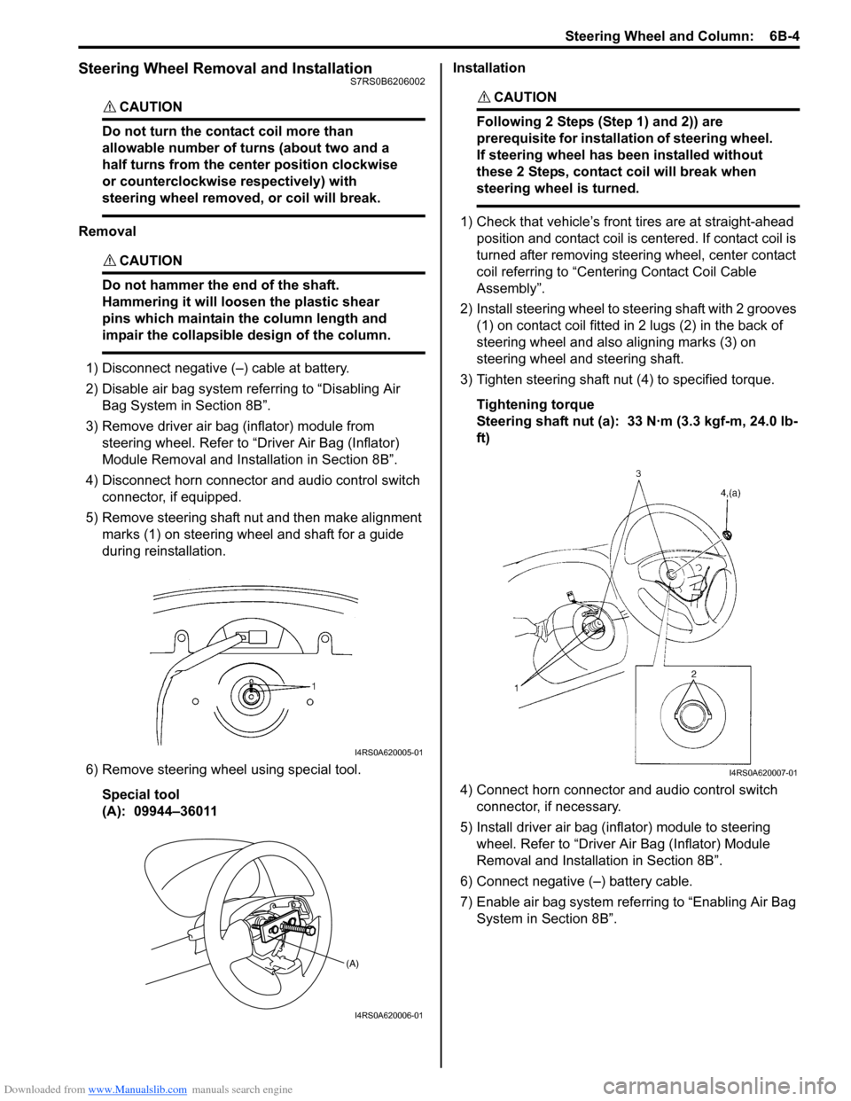
5) Remove steering shaft nut and then make alignment marks (1) on steering wheel and shaft for a guide
during reinstallation.
6) Remove steering wheel using special tool. Special tool
(A): 09944–36011 Installation
CAUTION!
Following 2 Steps (Step 1) and 2)) are
prerequisite for installation of steering wheel.
If steering wheel has
been installed without
these 2 Steps, contact coil will break when
steering wheel is turned.
1) Check that vehicle’s front tires are at straight-ahead position and contact coil is centered. If contact coil is
turned after removing steering wheel, center contact
coil referring to “Centering Contact Coil Cable
Assembly”.
2) Install steering wheel to steering shaft with 2 grooves (1) on contact coil fitted in 2 lugs (2) in the back of
steering wheel and also aligning marks (3) on
steering wheel and steering shaft.
3) Tighten steering shaft nut (4) to specified torque.
Tightening torque
Steering shaft nut (a): 33 N·m (3.3 kgf-m, 24.0 lb-
ft)
4) Connect horn connector and audio control switch connector, if necessary.
5) Install driver air bag (inflator) module to steering wheel. Refer to “Driver Air Bag (Inflator) Module
Removal and Installati on in Section 8B”.
6) Connect negative (–) battery cable.
7) Enable air bag system refe rring to “Enabling Air Bag
System in Section 8B”.
I4RS0A620005-01
(A)
I4RS0A620006-01
I4RS0A620007-01
Page 881 of 1496
Downloaded from www.Manualslib.com manuals search engine Steering Wheel and Column: 6B-10
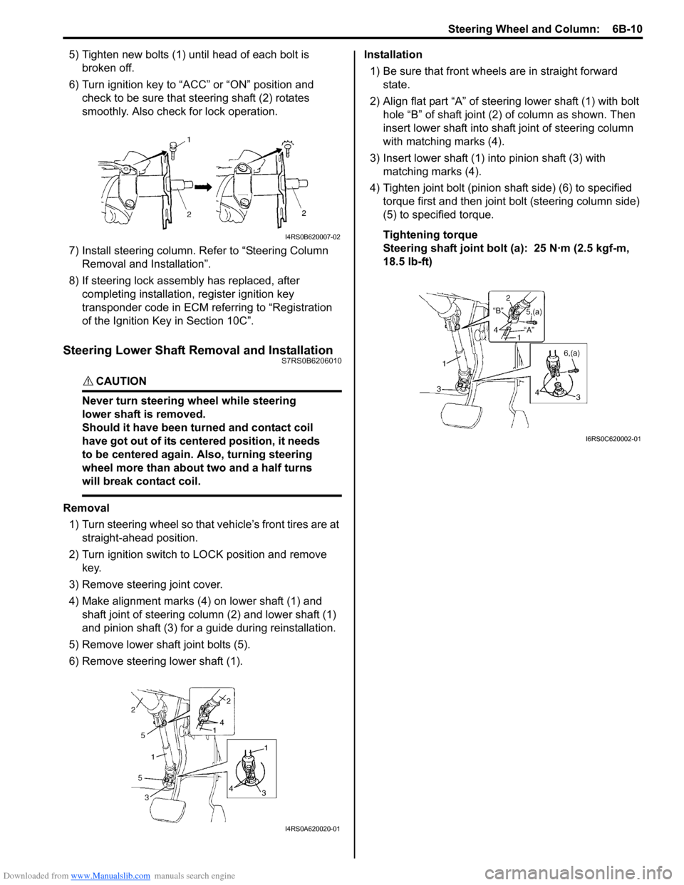
5) Tighten new bolts (1) until head of each bolt is broken off.
6) Turn ignition key to “ACC” or “ON” position and check to be sure that st eering shaft (2) rotates
smoothly. Also check for lock operation.
7) Install steering column. Re fer to “Steering Column
Removal and Installation”.
8) If steering lock assembly has replaced, after completing installation, register ignition key
transponder code in ECM referring to “Registration
of the Ignition Key in Section 10C”.
Steering Lower Shaft Removal and InstallationS7RS0B6206010
CAUTION!
Never turn steering wheel while steering
lower shaft is removed.
Should it have been turned and contact coil
have got out of its centered position, it needs
to be centered again. Also, turning steering
wheel more than about two and a half turns
will break contact coil.
Removal
1) Turn steering wheel so that vehicle’s front tires are at straight-ahead position.
2) Turn ignition switch to LOCK position and remove key.
3) Remove steering joint cover.
4) Make alignment marks (4) on lower shaft (1) and shaft joint of steering colu mn (2) and lower shaft (1)
and pinion shaft (3) for a guide during reinstallation.
5) Remove lower shaf t joint bolts (5).
6) Remove steering lower shaft (1). Installation
1) Be sure that front wheels are in straight forward state.
2) Align flat part “A” of steering lower shaft (1) with bolt hole “B” of shaft joint (2) of column as shown. Then
insert lower shaft into shaf t joint of steering column
with matching marks (4).
3) Insert lower shaft (1) into pinion shaft (3) with matching marks (4).
4) Tighten joint bolt (pinion shaft side) (6) to specified
torque first and then joint bolt (steering column side)
(5) to specified torque.
Tightening torque
Steering shaft joint bolt (a ): 25 N·m (2.5 kgf-m,
18.5 lb-ft)
I4RS0B620007-02
I4RS0A620020-01
I6RS0C620002-01
Page 921 of 1496
Downloaded from www.Manualslib.com manuals search engine Power Assisted Steering System: 6C-39
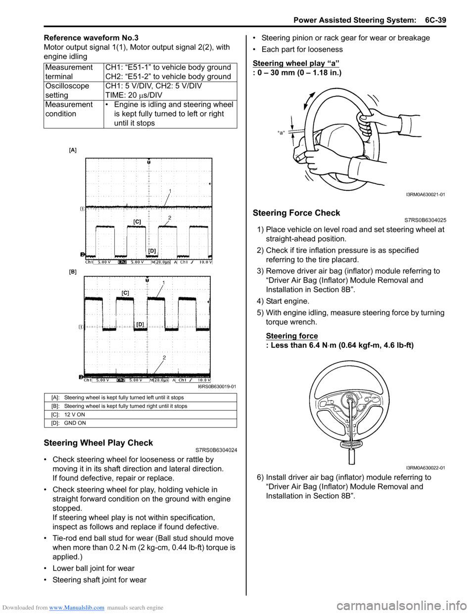
Reference waveform No.3
Motor output signal 1(1), Motor output signal 2(2), with
engine idling
Steering Wheel Play CheckS7RS0B6304024
• Check steering wheel for looseness or rattle by moving it in its shaft direction and lateral direction.
If found defective, repair or replace.
• Check steering wheel for play, holding vehicle in straight forward condition on the ground with engine
stopped.
If steering wheel play is not within specification,
inspect as follows and replace if found defective.
• Tie-rod end ball stud for wear (Ball stud should move when more than 0.2 N ⋅m (2 kg-cm, 0.44 lb-ft) torque is
applied.)
• Lower ball joint for wear
• Steering shaft joint for wear • Steering pinion or rack gear for wear or breakage
• Each part for looseness
Steering wheel play
“a”
: 0 – 30 mm (0 – 1.18 in.)
Steering Force CheckS7RS0B6304025
1) Place vehicle on level road and set steering wheel at
straight-ahead position.
2) Check if tire inflation pressure is as specified referring to the tire placard.
3) Remove driver air bag (inflator) module referring to “Driver Air Bag (Inflator) Module Removal and
Installation in Section 8B”.
4) Start engine.
5) With engine idling, measure steering force by turning torque wrench.
Steering force
: Less than 6.4 N ⋅m (0.64 kgf-m, 4.6 lb-ft)
6) Install driver air bag (inflator) module referring to “Driver Air Bag (Inflator) Module Removal and
Installation in Section 8B”.
Measurement
terminal
CH1: “E51-1” to vehicle body ground
CH2: “E51-2” to vehicle body ground
Oscilloscope
setting CH1: 5 V/DIV, CH2: 5 V/DIV
TIME: 20
µs/DIV
Measurement
condition • Engine is idling and steering wheel
is kept fully turned to left or right
until it stops
[A]: Steering wheel is kept fully turned left until it stops
[B]: Steering wheel is kept fully turned right until it stops
[C]: 12 V ON
[D]: GND ON
I6RS0B630019-01
I3RM0A630021-01
I3RM0A630022-01
Page 1136 of 1496
Downloaded from www.Manualslib.com manuals search engine 8B-98 Air Bag System:
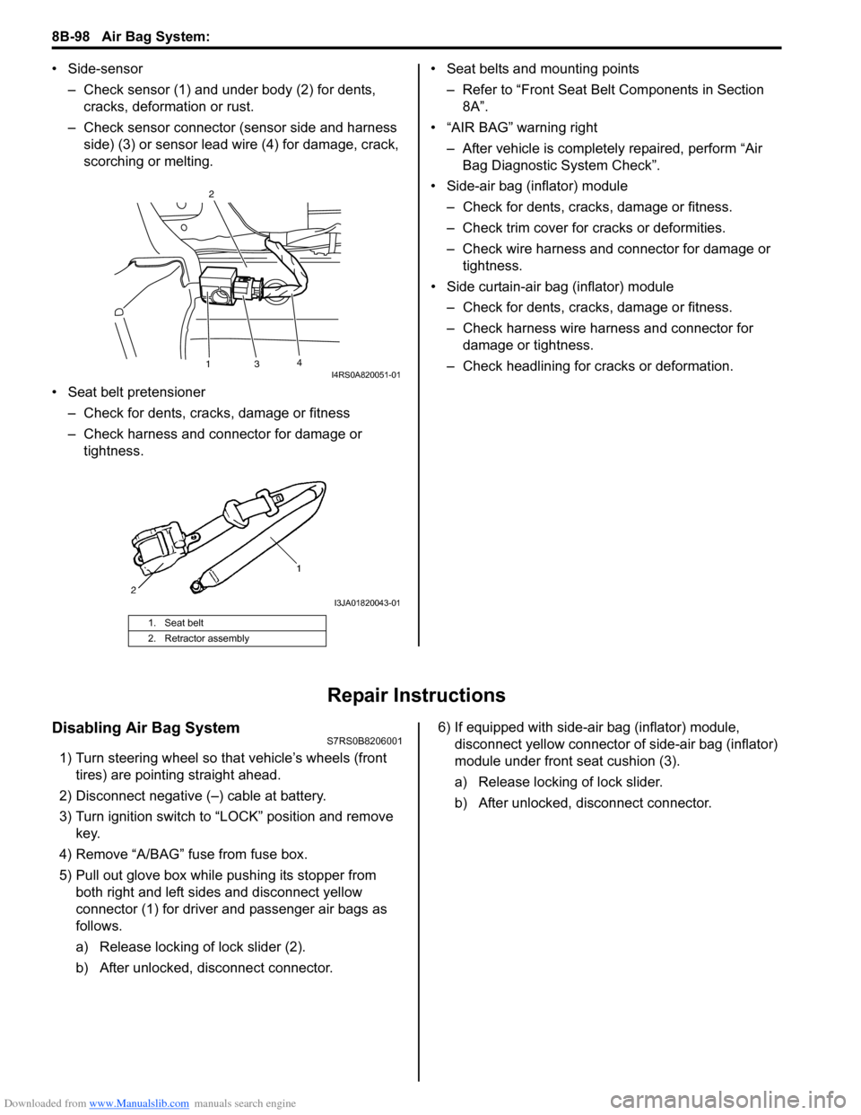
• Side-sensor– Check sensor (1) and under body (2) for dents, cracks, deformation or rust.
– Check sensor connector (sensor side and harness side) (3) or sensor lead wire (4) for damage, crack,
scorching or melting.
• Seat belt pretensioner – Check for dents, cracks , damage or fitness
– Check harness and connector for damage or tightness. • Seat belts and mounting points
– Refer to “Front Seat Belt Components in Section 8A”.
• “AIR BAG” warning right
– After vehicle is completely repaired, perform “Air Bag Diagnostic System Check”.
• Side-air bag (inflator) module – Check for dents, cra cks, damage or fitness.
– Check trim cover for cracks or deformities.
– Check wire harness and connector for damage or tightness.
• Side curtain-air bag (inflator) module – Check for dents, cra cks, damage or fitness.
– Check harness wire harness and connector for damage or tightness.
– Check headlining for cracks or deformation.
Repair Instructions
Disabling Air Bag SystemS7RS0B8206001
1) Turn steering wheel so that vehicle’s wheels (front tires) are pointing straight ahead.
2) Disconnect negative (–) cable at battery.
3) Turn ignition switch to “LOCK” position and remove key.
4) Remove “A/BAG” fu se from fuse box.
5) Pull out glove box while pushing its stopper from
both right and left sides and disconnect yellow
connector (1) for driver and passenger air bags as
follows.
a) Release locking of lock slider (2).
b) After unlocked, disconnect connector. 6) If equipped with side-air bag (inflator) module,
disconnect yellow connector of side-air bag (inflator)
module under front seat cushion (3).
a) Release locking of lock slider.
b) After unlocked, disconnect connector.
1. Seat belt
2. Retractor assembly
13 4
2I4RS0A820051-01
I3JA01820043-01
Page 1151 of 1496
Downloaded from www.Manualslib.com manuals search engine Air Bag System: 8B-113
Air Bag (Inflator) Module and Seat Belt
Pretensioner Disposal
S7RS0B8206018
WARNING!
Failure to follow proper air bag (inflator)
module and seat belt pretensioner disposal
procedures can result in air bag deployment
and pretensioner activation which may cause
personal injury. Do not dispose of live
(undeployed) air bag (inflator) modules and
seat belt pretensioners. Because undeployed
air bag (inflator) module / inactivated seat
belt pretensioner must not be disposed of
through normal refuse channels. Undeployed
air bag (inflator) module and inactivated seat
belt pretensioner contain substances that
can cause severe illness or personal injury if
sealed container is damaged during disposal.
Air bag (inflator) module / seat belt pretensioner can be
deployed / activated inside or outside of vehicle.
Deployment / Activation method used depends upon
final disposition of vehicle. Review the following
instructions in order to deter mine which will work best in
a given situation.
Deployment / Activation Ou tside of Vehicle: When you
intend to return the vehicle to service, deploy the air bag
(inflator) module(s) and/or activate seat belt
pretensioner(s) outside of the vehicle.
Deployment / Activation Insi de of Vehicle: When the
vehicle will be destroyed, or salvaged for component
parts, deploy the air bag module(s) and/or activate seat
belt pretensioner(s) installed on vehicle.
WARNING!
The following precautions must be observed
for this work. Failure to observe any of them
may result in personal injury.
• Procedure should be followed strictly as described here.
• Be sure to read “Precautions on Service and Diagnosis of Air Bag System”
beforehand.
• To avoid accidental deployment / activation, this work should be performed
by no more than one person.
• Since smoke is produced when air bag (inflator) module is deployed and
pretensioner is activated, select well-
ventilated area.
• Air bag (inflator) module and seat belt pretensioner will immediately deploy /
activate when 12 volts vehicle battery is
connected to it. Wear safety glasses
throughout this entire deployment /
activation and disposal procedure.
• Wear suitable ear protection when deploying air bag (inflator) module /
activating seat belt pretensioner. Also,
advise those who are in area close to
deployment / activation site to wear
suitable ear protection.
• Do not deploy / activate two or more air bag system components (air bag (inflator)
modules and seat belt pretensioners) at
the same time.
• Never connect deployment harness to any 12 volts vehicle battery before connecting
deployment harness to air bag (inflator)
module and seat belt pretensioner.
Deployment harness sh all remain shorted
and not be connected to 12 volts vehicle
battery till you are ready to deploy air bag
(inflator) module or activate seat belt
pretensioner.