member SUZUKI SWIFT 2008 2.G Service User Guide
[x] Cancel search | Manufacturer: SUZUKI, Model Year: 2008, Model line: SWIFT, Model: SUZUKI SWIFT 2008 2.GPages: 1496, PDF Size: 34.44 MB
Page 1367 of 1496
Downloaded from www.Manualslib.com manuals search engine Interior Trim: 9H-1
Body, Cab and Accessories
Interior Trim
Repair Instructions
Floor Carpet Removal and InstallationS7RS0B9806001
WARNING!
Refer to “Air Bag Warning in Section 00”
before starting service work.
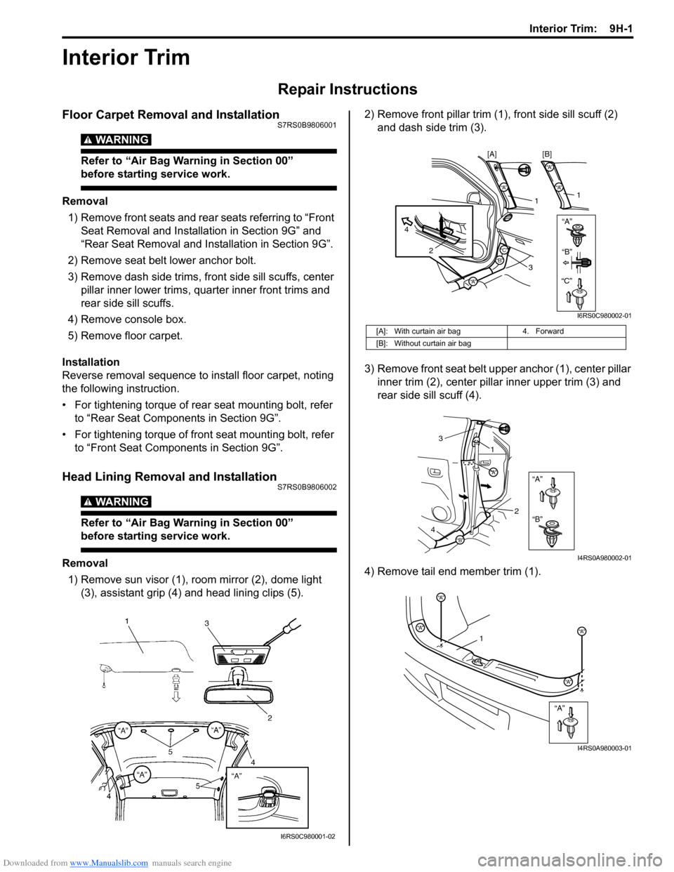
Removal1) Remove front seats and rear seats referring to “Front Seat Removal and Installa tion in Section 9G” and
“Rear Seat Removal and Installation in Section 9G”.
2) Remove seat belt lower anchor bolt.
3) Remove dash side trims, fr ont side sill scuffs, center
pillar inner lower trims, qu arter inner front trims and
rear side sill scuffs.
4) Remove console box.
5) Remove floor carpet.
Installation
Reverse removal sequence to install floor carpet, noting
the following instruction.
• For tightening torque of rear seat mounting bolt, refer to “Rear Seat Components in Section 9G”.
• For tightening torque of front seat mounting bolt, refer to “Front Seat Components in Section 9G”.
Head Lining Removal and InstallationS7RS0B9806002
WARNING!
Refer to “Air Bag Warning in Section 00”
before starting service work.
Removal
1) Remove sun visor (1), room mirror (2), dome light (3), assistant grip (4) and head lining clips (5). 2) Remove front pillar trim (1
), front side sill scuff (2)
and dash side trim (3).
3) Remove front seat belt u pper anchor (1), center pillar
inner trim (2), center pillar inner upper trim (3) and
rear side sill scuff (4).
4) Remove tail end member trim (1).
I6RS0C980001-02
[A]: With curtain air bag 4. Forward
[B]: Without curtain air bag
“A”“A”
“A”
2
4
1
3
“A”
“A”
1
[B]
[A]
“B”“B”
“C”“C”
I6RS0C980002-01
“A”
“B”
“A”
“B”
1
3
2
4
I4RS0A980002-01
“A”
“A”
“A”
“A”“A”1
I4RS0A980003-01
Page 1378 of 1496
Downloaded from www.Manualslib.com manuals search engine 9K-1 Body Structure:
Body, Cab and Accessories
Body Structure
Repair Instructions
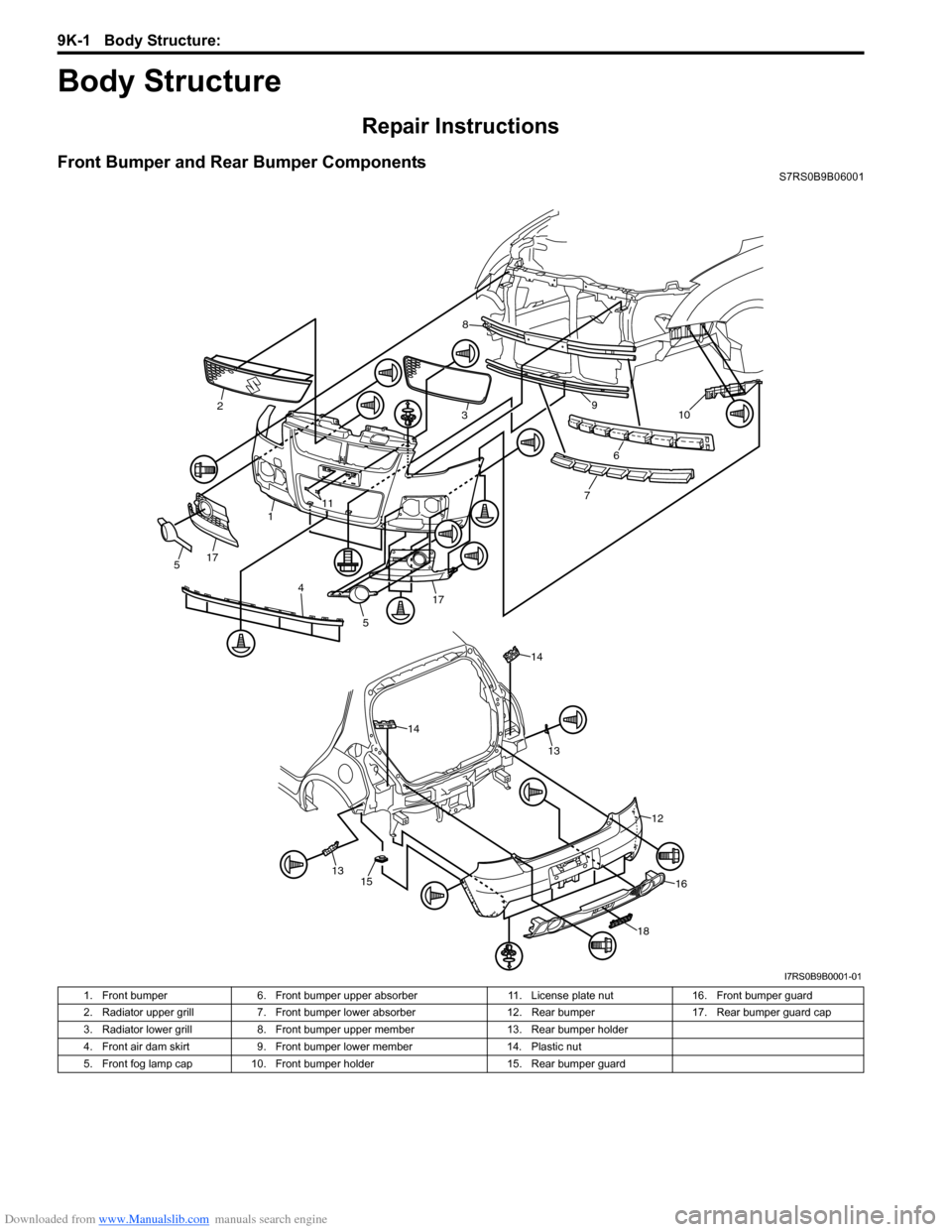
Front Bumper and Rear Bumper ComponentsS7RS0B9B06001
10
6
79
8
32
1
5
4 1117
175
1315
14
12
16
18
14
13
I7RS0B9B0001-01
1. Front bumper
6. Front bumper upper absorber 11. License plate nut16. Front bumper guard
2. Radiator upper grill 7. Front bumper lower absorber 12. Rear bumper17. Rear bumper guard cap
3. Radiator lower grill 8. Front bumper upper member 13. Rear bumper holder
4. Front air dam skirt 9. Front bumper lower member 14. Plastic nut
5. Front fog lamp cap 10. Front bumper holder 15. Rear bumper guard
Page 1380 of 1496
Downloaded from www.Manualslib.com manuals search engine 9K-3 Body Structure:
Specifications
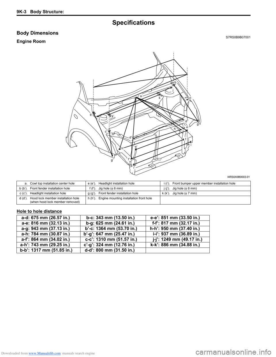
Body DimensionsS7RS0B9B07001
Engine Room
Hole to hole distance
g’
b
ckg
i
a
b’
c’
d
d’
e
e’
f’
f
h
h’
i’ j
k’
j’
I4RS0A9B0003-01
a. Cowl top installation center hole e (e’). Headlight installation hole i (i’). Front bumper upper member installation hole
b (b’). Front fender installation hole f (f’). Jig hole (φ 8 mm) j (j’). Jig hole (φ 8 mm)
c (c’). Headlight installation hole g (g’). Front fender installation hole k (k’). Jig hole (φ 7 mm)
d (d’). Hood lock member installation hole (when hood lock member removed) h (h’). Engine mounting installation front hole
a-d: 675 mm (26.57 in.) b-c: 343 mm (13.50 in.) e-e’: 851 mm (33.50 in.)
a-e: 816 mm (32.13 in.) b-g: 625 mm (24.61 in.) f-f’: 817 mm (32.17 in.)
a-g: 943 mm (37.13 in.) b’-c: 1364 mm (53.70 in.) h-h’: 950 mm (37.40 in.)
a-h: 784 mm (30.87 in.) b’-g’: 647 mm (25.47 in.) i-i’: 937 mm (36.89 in.)
a-f’: 864 mm (34.02 in.) c-c’: 1310 mm (51.57 in.) j-j’: 1249 mm (49.17 in.)
a-h’: 743 mm (29.25 in.) c’-g’: 324 mm (12.76 in.) k-k’: 886 mm (34.88 in.)
b-b’: 1317 mm (51.85 in.) d-d’: 800 mm (31.50 in.)
Page 1381 of 1496
Downloaded from www.Manualslib.com manuals search engine Body Structure: 9K-4
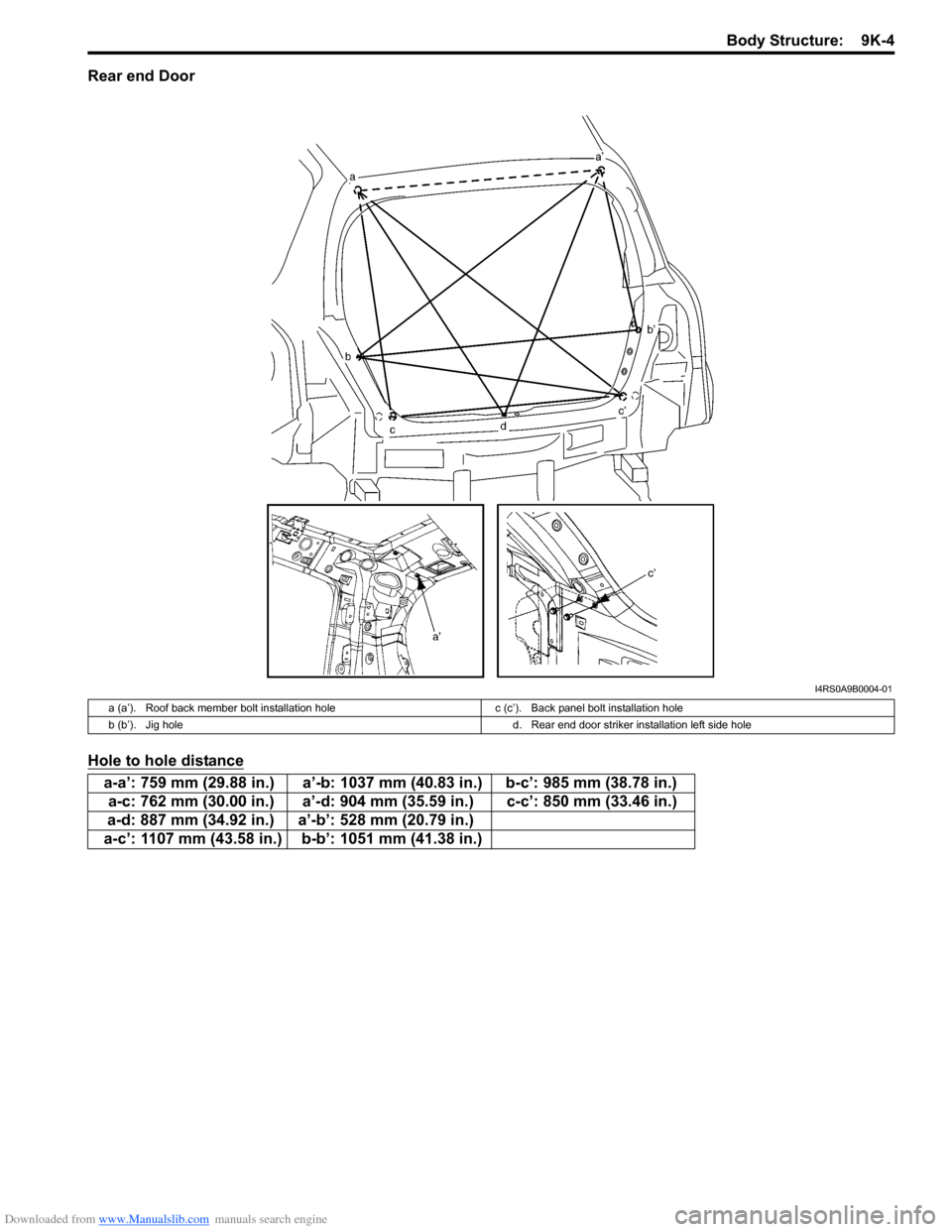
Rear end Door
Hole to hole distance
I4RS0A9B0004-01
a (a’). Roof back member bolt installation holec (c’). Back panel bolt installation hole
b (b’). Jig hole d. Rear end door striker installation left side hole
a-a’: 759 mm (29.88 in.) a’-b: 1037 mm (40.83 in.) b-c’: 985 mm (38.78 in.)
a-c: 762 mm (30.00 in.) a’-d: 904 mm (35.59 in.) c-c’: 850 mm (33.46 in.)
a-d: 887 mm (34.92 in.) a’-b’: 528 mm (20.79 in.)
a-c’: 1107 mm (43.58 in.) b-b’: 1051 mm (41.38 in.)
Page 1492 of 1496
Downloaded from www.Manualslib.com manuals search engine 10E-30 Keyless Start System:
Repair Instructions
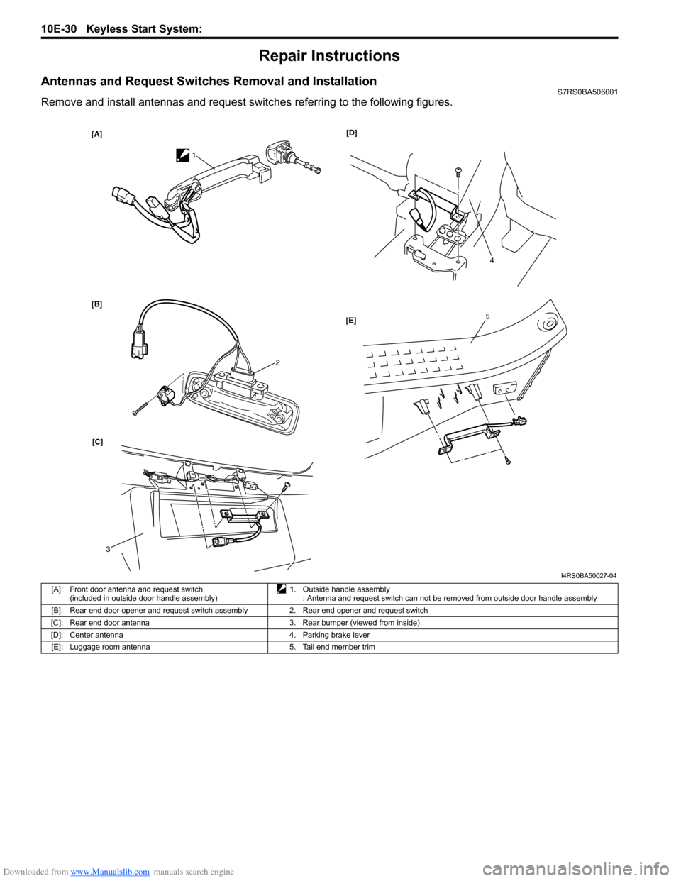
Antennas and Request Switches Removal and InstallationS7RS0BA506001
Remove and install antennas and request switches referring to the following figures.
[A]
[B][D]
[C] [E]
1
2
3
4
5
I4RS0BA50027-04
[A]: Front door antenna and request switch
(included in outside door handle assembly) 1. Outside handle assembly
: Antenna and request switch can not be removed from outside door handle assembly
[B]: Rear end door opener and request switch assembly 2. Rear end opener and request switch
[C]: Rear end door antenna 3. Rear bumper (viewed from inside)
[D]: Center antenna 4. Parking brake lever [E]: Luggage room antenna 5. Tail end member trim
Page 1494 of 1496
Downloaded from www.Manualslib.com manuals search engine 10E-32 Keyless Start System:
Keyless Start Control Module Removal and
Installation
S7RS0BA506006
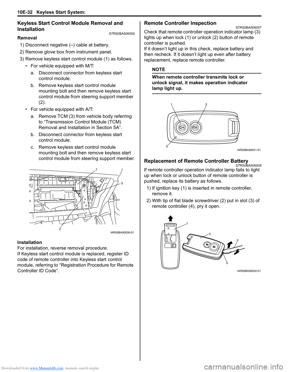
Removal1) Disconnect negative (–) cable at battery.
2) Remove glove box from instrument panel.
3) Remove keyless start cont rol module (1) as follows.
• For vehicle equipped with M/T:
a. Disconnect connector from keyless start control module.
b. Remove keyless start control module mounting bolt and then remove keyless start
control module from steering support member
(2).
• For vehicle equipped with A/T: a. Remove TCM (3) from vehicle body referring to “Transmission Control Module (TCM)
Removal and Installation in Section 5A”.
b. Disconnect connector from keyless start control module.
c. Remove keyless start control module mounting bolt and then remove keyless start
control module from steering support member.
Installation
For installation, reverse removal procedure.
If Keyless start control module is replaced, register ID
code of remote controller in to Keyless start control
module, referring to “Registration Procedure for Remote
Controller ID Code”.
Remote Controller InspectionS7RS0BA506007
Check that remote controller operation indicator lamp (3)
lights up when lock (1) or un lock (2) button of remote
controller is pushed.
If it doesn’t light up in this check, replace battery and
then recheck. If it doesn’t light up even after battery
replacement, replace remote controller.
NOTE
When remote controller transmits lock or
unlock signal, it makes operation indicator
lamp light up.
Replacement of Remote Controller BatteryS7RS0BA506008
If remote controller operation i ndicator lamp fails to light
up when lock or unlock button of remote controller is
pushed, replace its battery as follows.
1) If ignition key (1) is inse rted in remote controller,
remove it.
2) With tip of flat blade screwdriver (2) put in slot (3) of remote controller (4), pry it open.1
3
2
I4RS0BA50030-01
12
3I4RS0BA50031-01
1
4
2
3
I4RS0BA50032-01