wire color SUZUKI SWIFT 2008 2.G Service User Guide
[x] Cancel search | Manufacturer: SUZUKI, Model Year: 2008, Model line: SWIFT, Model: SUZUKI SWIFT 2008 2.GPages: 1496, PDF Size: 34.44 MB
Page 230 of 1496
Downloaded from www.Manualslib.com manuals search engine 1A-180 Engine General Information and Diagnosis:
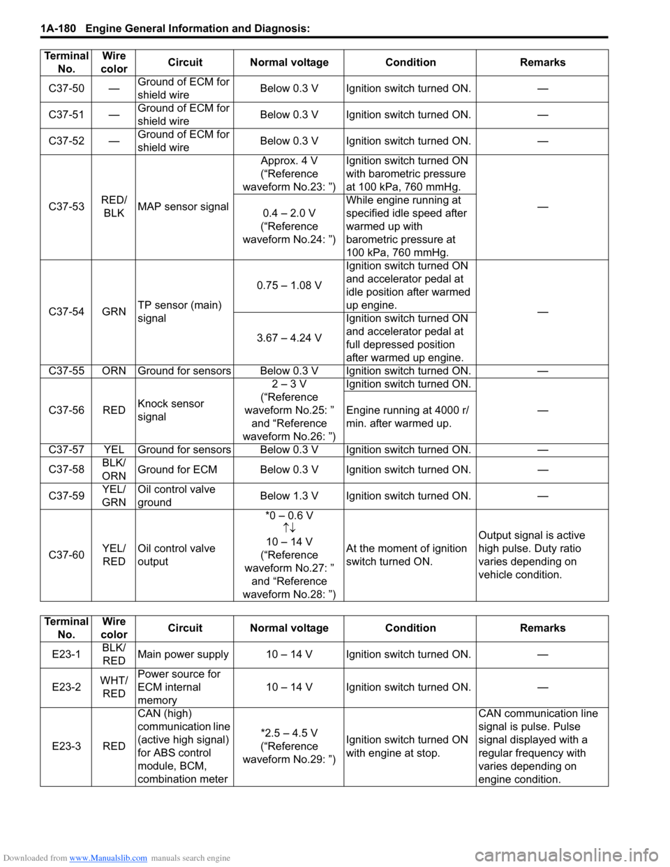
C37-50 βGround of ECM for
shield wire Below 0.3 V Ignition switch turned ON. β
C37-51 β Ground of ECM for
shield wire Below 0.3 V Ignition switch turned ON. β
C37-52 β Ground of ECM for
shield wire Below 0.3 V Ignition switch turned ON. β
C37-53 RED/
BLK MAP sensor signal Approx. 4 V
(βReference
waveform No.23: β) Ignition switch turned ON
with barometric pressure
at 100 kPa, 760 mmHg.
β
0.4 β 2.0 V
(βReference
waveform No.24: β) While engine running at
specified idle speed after
warmed up with
barometric pressure at
100 kPa, 760 mmHg.
C37-54 GRN TP sensor (main)
signal 0.75 β 1.08 V
Ignition switch turned ON
and accelerator pedal at
idle position after warmed
up engine.
β
3.67 β 4.24 V Ignition switch turned ON
and accelerator pedal at
full depressed position
after warmed up engine.
C37-55 ORN Ground for sensors Below 0.3 V Ignition switch turned ON. β
C37-56 RED Knock sensor
signal 2 β 3 V
(βReference
waveform No.25: β and βReference
waveform No.26: β) Ignition switch turned ON.
β
Engine running at 4000 r/
min. after warmed up.
C37-57 YEL Ground for sensors Below 0.3 V Ignition switch turned ON. β
C37-58 BLK/
ORN Ground for ECM Below 0.3 V Ignition switch turned ON.
β
C37-59 YEL/
GRN Oil control valve
ground
Below 1.3 V Ignition switch turned ON.
β
C37-60 YEL/
RED Oil control valve
output *0 β 0.6 V
ββ
10 β 14 V
(βReference
waveform No.27: β and βReference
waveform No.28: β) At the moment of ignition
switch turned ON.
Output signal is active
high pulse. Duty ratio
varies depending on
vehicle condition.
Terminal
No. Wire
color Circuit Normal voltage
ConditionRemarks
Terminal
No. Wire
color Circuit Normal voltage Condition Remarks
E23-1 BLK/
RED Main power supply 10 β 14 V Ignition switch turned ON. β
E23-2 WHT/
RED Power source for
ECM internal
memory
10 β 14 V Ignition switch turned ON. β
E23-3 RED CAN (high)
communication line
(active high signal)
for ABS control
module, BCM,
combination meter *2.5 β 4.5 V
(βReference
waveform No.29: β) Ignition switch turned ON
with engine at stop. CAN communication line
signal is pulse. Pulse
signal displayed with a
regular frequency with
varies depending on
engine condition.
Page 231 of 1496
Downloaded from www.Manualslib.com manuals search engine Engine General Information and Diagnosis: 1A-181
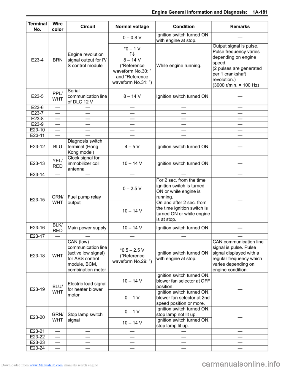
E23-4 BRNEngine revolution
signal output for P/
S control module 0 β 0.8 V
Ignition switch turned ON
with engine at stop. β
*0 β 1 V ββ
8 β 14 V
(βReference
waveform No.30: β and βReference
waveform No.31: β) While engine running. Output signal is pulse.
Pulse frequency varies
depending on engine
speed.
(2 pulses are generated
per 1 crankshaft
revolution.)
(3000 r/min. = 100 Hz)
E23-5 PPL/
WHT Serial
communication line
of DLC 12 V
8 β 14 V Ignition switch turned ON. β
E23-6 β β β β β
E23-7 β β β β β
E23-8 β β β β β
E23-9 β β β β β
E23-10 β β β β β E23-11 β β β β β
E23-12 BLU Diagnosis switch
terminal (Hong
Kong model) 4 β 5 V Ignition switch turned ON. β
E23-13 YEL/
RED Clock signal for
immobilizer coil
antenna
10 β 14 V Ignition switch turned ON. β
E23-14 β β β β β
E23-15 GRN/
WHT Fuel pump relay
output 0 β 2.5 V
For 2 sec. from the time
ignition switch is turned
ON or while engine is
running.
β
10 β 14 V On and after 2 sec. from
the time ignition switch is
turned ON or while engine
is at stop.
E23-16 BLK/
RED Main power supply 10 β 14 V Ignition switch turned ON. β
E23-17 β β β β β
E23-18 WHT CAN (low)
communication line
(active low signal)
for ABS control
module, BCM,
combination meter *0.5 β 2.5 V
(βReference
waveform No.29: β) Ignition switch turned ON
with engine at stop. CAN communication line
signal is pulse. Pulse
signal displayed with a
regular frequency which
varies depending on
engine condition.
E23-19 BLU/
WHT Electric load signal
for heater blower
motor 10 β 14 V
Ignition switch turned ON,
blower fan selector at OFF
position.
β
0 β 1 V Ignition switch turned ON,
blower fan selector at 2nd
speed position or more.
E23-20 GRN/
WHT Stop lamp switch
signal 0 β 1 V
Ignition switch turned ON,
stop lamp not lit up.
β
10 β 14 V Ignition switch turned ON,
stop lamp lit up.
E23-21 β β β β β
E23-22 β β β β β
E23-23 β β β β β
E23-24 β β β β β
Terminal
No. Wire
color Circuit Normal voltage Condition Remarks
Page 232 of 1496
Downloaded from www.Manualslib.com manuals search engine 1A-182 Engine General Information and Diagnosis:
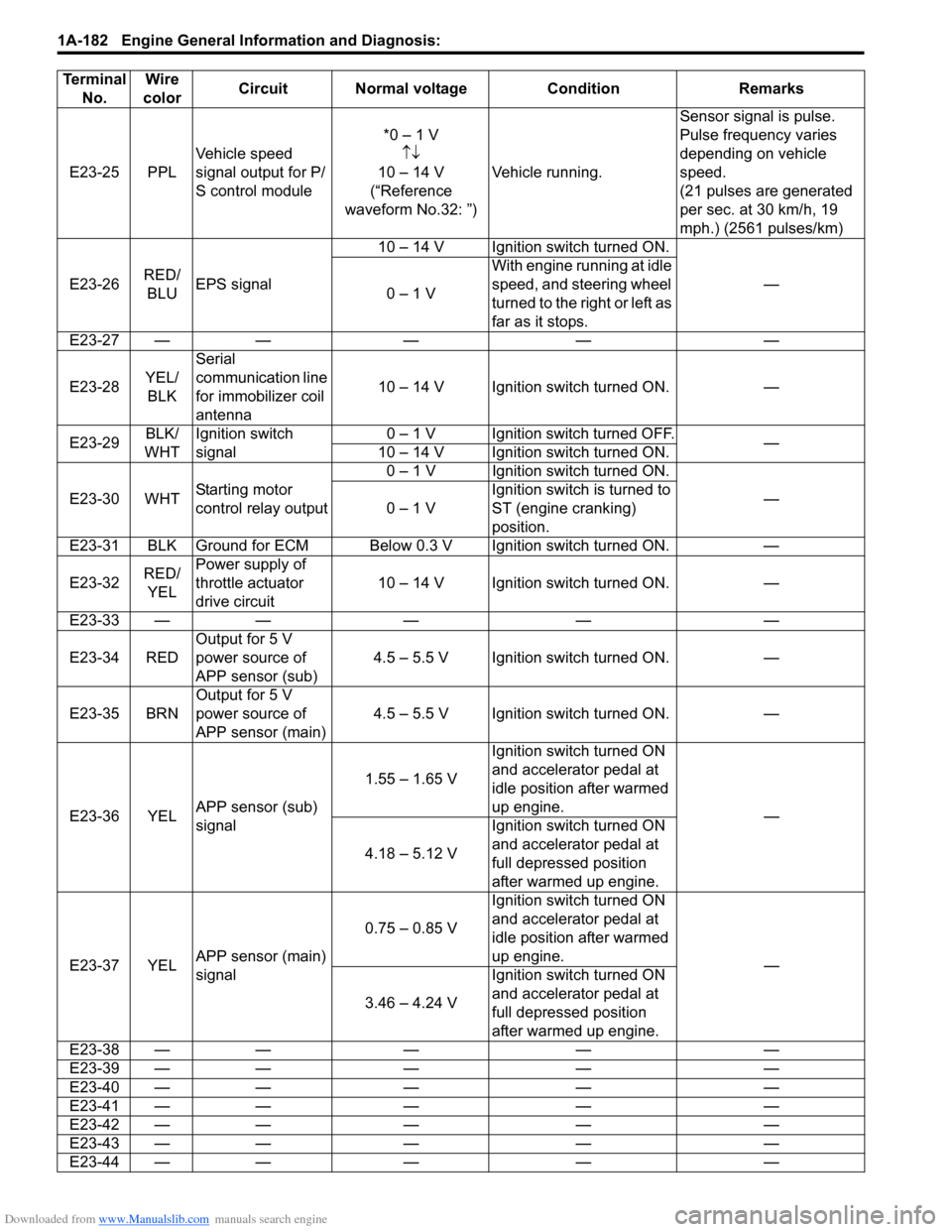
E23-25 PPLVehicle speed
signal output for P/
S control module *0 β 1 V
ββ
10 β 14 V
(βReference
waveform No.32: β) Vehicle running. Sensor signal is pulse.
Pulse frequency varies
depending on vehicle
speed.
(21 pulses are generated
per sec. at 30 km/h, 19
mph.) (2561 pulses/km)
E23-26 RED/
BLU EPS signal 10 β 14 V Ignition switch turned ON.
β
0 β 1 V With engine running at idle
speed, and steering wheel
turned to the right or left as
far as it stops.
E23-27 β β β β β
E23-28 YEL/
BLK Serial
communication line
for immobilizer coil
antenna
10 β 14 V Ignition switch turned ON. β
E23-29 BLK/
WHT Ignition switch
signal 0 β 1 V Ignition switch turned OFF.
β
10 β 14 V Ignition switch turned ON.
E23-30 WHT Starting motor
control relay output 0 β 1 V Ignition switch turned ON.
β
0 β 1 V Ignition switch is turned to
ST (engine cranking)
position.
E23-31 BLK Ground for ECM Below 0.3 V Ignition switch turned ON. β
E23-32 RED/
YEL Power supply of
throttle actuator
drive circuit
10 β 14 V Ignition switch turned ON. β
E23-33 β β β β β
E23-34 RED Output for 5 V
power source of
APP sensor (sub) 4.5 β 5.5 V Ignition switch turned ON. β
E23-35 BRN Output for 5 V
power source of
APP sensor (main) 4.5 β 5.5 V Ignition switch turned ON. β
E23-36 YEL APP sensor (sub)
signal 1.55 β 1.65 V
Ignition switch turned ON
and accelerator pedal at
idle position after warmed
up engine.
β
4.18 β 5.12 V Ignition switch turned ON
and accelerator pedal at
full depressed position
after warmed up engine.
E23-37 YEL APP sensor (main)
signal 0.75 β 0.85 V
Ignition switch turned ON
and accelerator pedal at
idle position after warmed
up engine.
β
3.46 β 4.24 V Ignition switch turned ON
and accelerator pedal at
full depressed position
after warmed up engine.
E23-38 β β β β β
E23-39 β β β β β
E23-40 β β β β β
E23-41 β β β β β
E23-42 β β β β β
E23-43 β β β β β
E23-44 β β β β β
Terminal
No. Wire
color Circuit Normal voltage Condition Remarks
Page 233 of 1496
Downloaded from www.Manualslib.com manuals search engine Engine General Information and Diagnosis: 1A-183
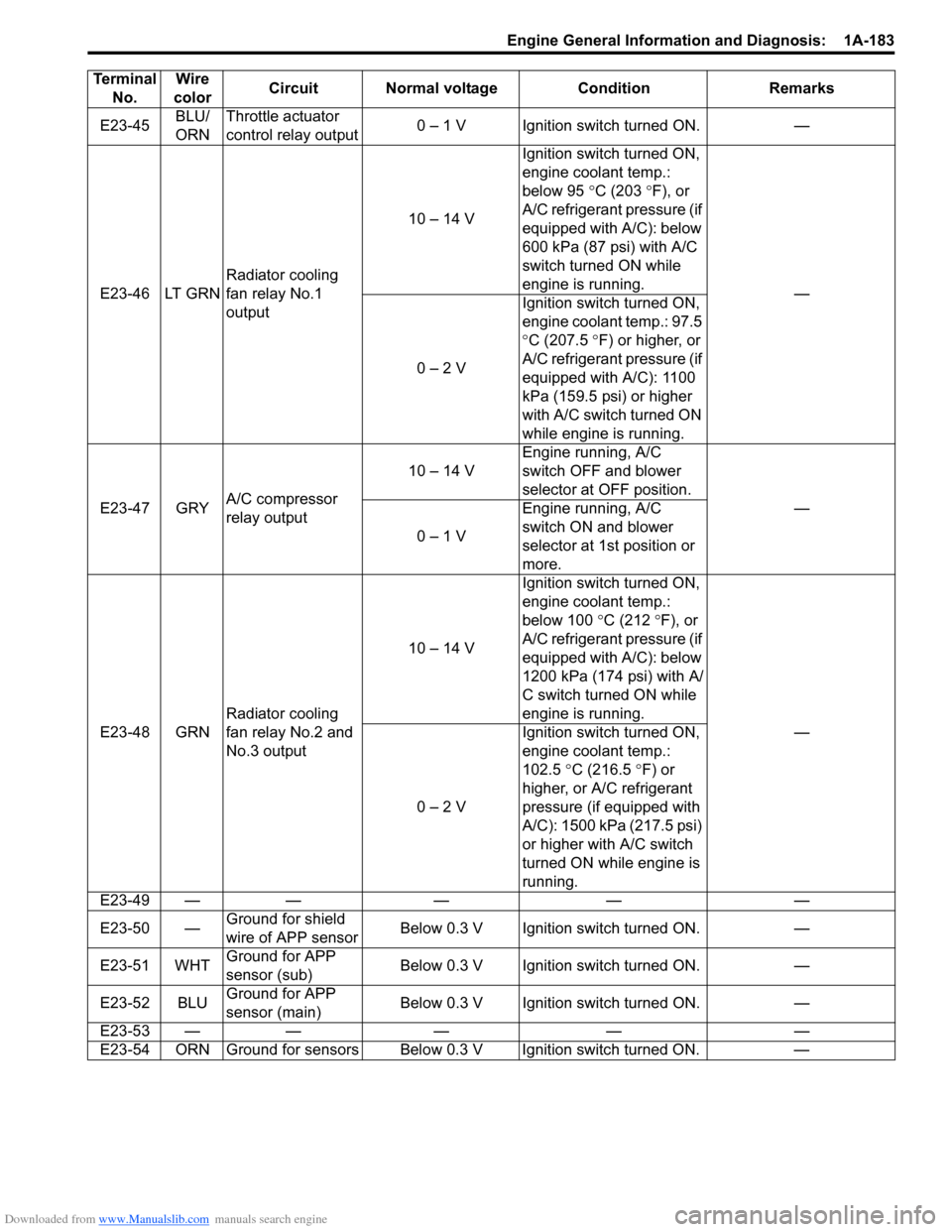
E23-45BLU/
ORNThrottle actuator
control relay output
0 β 1 V Ignition switch turned ON. β
E23-46 LT GRN Radiator cooling
fan relay No.1
output 10 β 14 V
Ignition switch turned ON,
engine coolant temp.:
below 95
Β°C (203 Β° F), or
A/C refrigerant pressure (if
equipped with A/C): below
600 kPa (87 psi) with A/C
switch turned ON while
engine is running. β
0 β 2 V Ignition switch turned ON,
engine coolant temp.: 97.5
Β°
C (207.5 Β° F) or higher, or
A/C refrigerant pressure (if
equipped with A/C): 1100
kPa (159.5 psi) or higher
with A/C switch turned ON
while engine is running.
E23-47 GRY A/C compressor
relay output 10 β 14 V
Engine running, A/C
switch OFF and blower
selector at OFF position.
β
0 β 1 V Engine running, A/C
switch ON and blower
selector at 1st position or
more.
E23-48 GRN Radiator cooling
fan relay No.2 and
No.3 output 10 β 14 V
Ignition switch turned ON,
engine coolant temp.:
below 100
Β°C (212 Β°F), or
A/C refrigerant pressure (if
equipped with A/C): below
1200 kPa (174 psi) with A/
C switch turned ON while
engine is running. β
0 β 2 V Ignition switch turned ON,
engine coolant temp.:
102.5
Β°C (216.5 Β°F) or
higher, or A/C refrigerant
pressure (if equipped with
A/C): 1500 kPa (217.5 psi)
or higher with A/C switch
turned ON while engine is
running.
E23-49 β β β β β
E23-50 β Ground for shield
wire of APP sensor Below 0.3 V Ignition switch turned ON. β
E23-51 WHT Ground for APP
sensor (sub) Below 0.3 V Ignition switch turned ON. β
E23-52 BLU Ground for APP
sensor (main) Below 0.3 V Ignition switch turned ON. β
E23-53 β β β β β
E23-54 ORN Ground for sensors Below 0.3 V Ignition switch turned ON. β
Terminal
No. Wire
color Circuit Normal voltage Condition Remarks
Page 234 of 1496
Downloaded from www.Manualslib.com manuals search engine 1A-184 Engine General Information and Diagnosis:
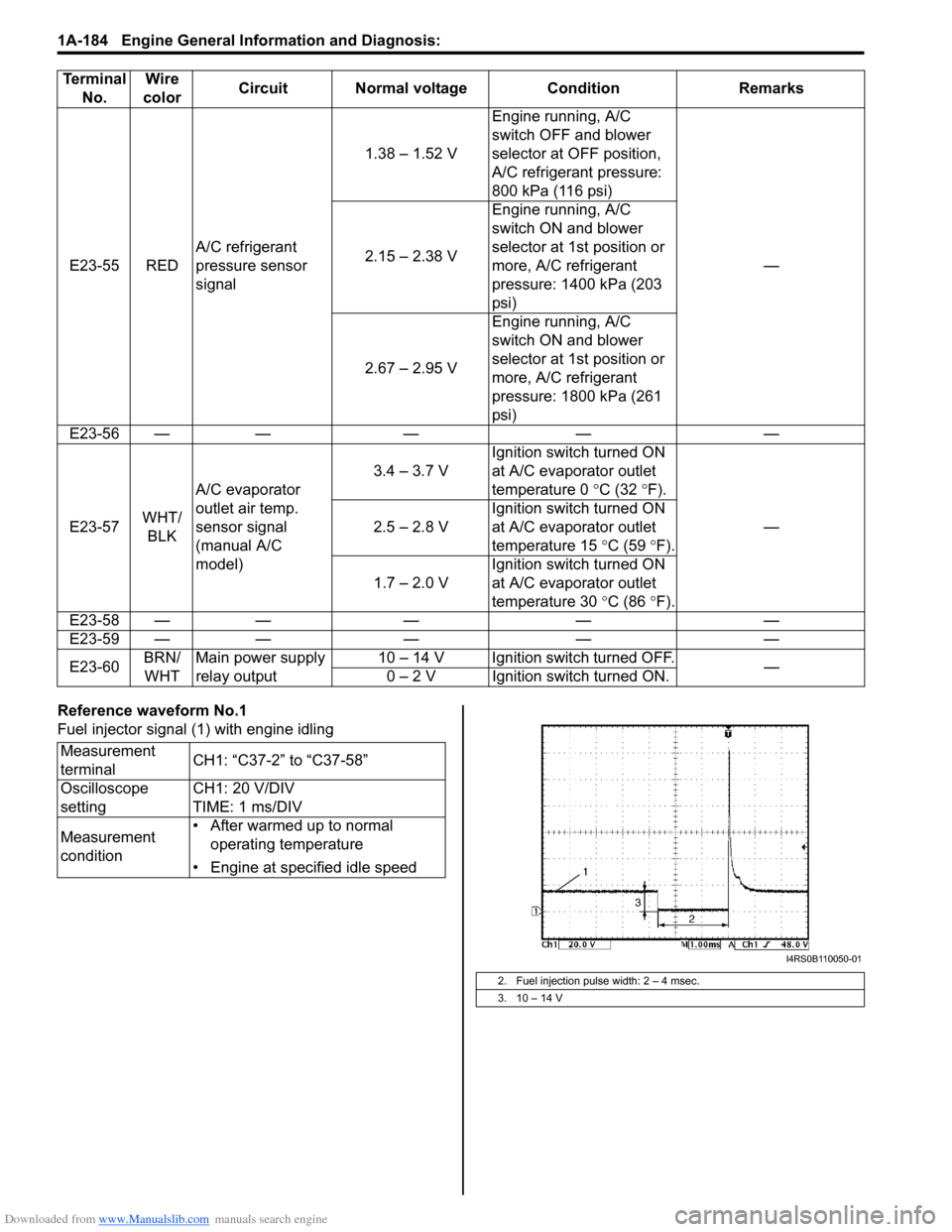
Reference waveform No.1
Fuel injector signal (1) with engine idling
E23-55 RED
A/C refrigerant
pressure sensor
signal 1.38 β 1.52 V
Engine running, A/C
switch OFF and blower
selector at OFF position,
A/C refrigerant pressure:
800 kPa (116 psi)
β
2.15 β 2.38 V Engine running, A/C
switch ON and blower
selector at 1st position or
more, A/C refrigerant
pressure: 1400 kPa (203
psi)
2.67 β 2.95 V Engine running, A/C
switch ON and blower
selector at 1st position or
more, A/C refrigerant
pressure: 1800 kPa (261
psi)
E23-56 β β β β β
E23-57 WHT/
BLK A/C evaporator
outlet air temp.
sensor signal
(manual A/C
model) 3.4 β 3.7 V
Ignition switch turned ON
at A/C evaporator outlet
temperature 0
Β°C (32 Β°F).
β
2.5 β 2.8 V Ignition switch turned ON
at A/C evaporator outlet
temperature 15
Β°C (59 Β°F).
1.7 β 2.0 V Ignition switch turned ON
at A/C evaporator outlet
temperature 30
Β°C (86 Β°F).
E23-58 β β β β β
E23-59 β β β β β
E23-60 BRN/
WHT Main power supply
relay output 10 β 14 V Ignition switch turned OFF.
β
0 β 2 V Ignition switch turned ON.
Terminal
No. Wire
color Circuit Normal voltage Condition Remarks
Measurement
terminal CH1: βC37-2β to βC37-58β
Oscilloscope
setting CH1: 20 V/DIV
TIME: 1 ms/DIV
Measurement
condition β’ After warmed up to normal
operating temperature
β’ Engine at specified idle speed
2. Fuel injection pulse width: 2 β 4 msec.
3. 10 β 14 V
I4RS0B110050-01
Page 545 of 1496
Downloaded from www.Manualslib.com manuals search engine ABS: 4E-6
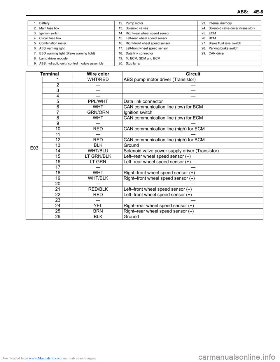
1. Battery12. Pump motor23. Internal memory
2. Main fuse box 13. Solenoid valves24. Solenoid valve driver (transistor)
3. Ignition switch 14. Right-rear wheel speed sensor25. ECM
4. Circuit fuse box 15. Left-rear wheel speed sensor26. BCM
5. Combination meter 16. Right-front wheel speed sensor27. Brake fluid level switch
6. ABS warning light 17. Left-front wheel speed sensor28. Parking brake switch
7. EBD warning light (Brake warning light) 18. Data link connector29. CAN driver
8. Lamp driver module 19. To ECM, SDM and BCM
9. ABS hydraulic unit / control module assembly 20. Stop lamp
Terminal Wire color Circuit
E03 1
WHT/RED ABS pump motor driver (Transistor)
2β β
3β β
4β β
5 PPL/WHT Data link connector
6 WHT CAN communication line (low) for BCM
7 GRN/ORN Ignition switch
8 WHT CAN communication line (low) for ECM
9β β
10 RED CAN communication line (high) for ECM
11 β β
12 RED CAN communication line (high) for BCM
13 BLK Ground
14 WHT/BLU Solenoid valve power supply driver (Transistor)
15 LT GRN/BLK Leftβrear wheel speed sensor (β)
16 LT GRN Leftβrear wheel speed sensor (+)
17 β β
18 WHT Rightβfront wheel speed sensor (+)
19 WHT/BLK Rightβfront wheel speed sensor (β)
20 β β
21 RED/BLK Leftβfront wheel speed sensor (β)
22 RED Leftβfront wheel speed sensor (+)
23 β β
24 YEL Rightβrear wheel speed sensor (+)
25 BRN Rightβrear wheel speed sensor (β)
26 BLK Ground
Page 662 of 1496

Downloaded from www.Manualslib.com manuals search engine 5A-18 Automatic Transmission/Transaxle:
Visual InspectionS7RS0B5104002
Visually check the following parts and systems.
Malfunction Indicator Lamp (MIL) CheckS7RS0B5104003
Refer to the same item in βMalfunction Indicator Lam p (MIL) Check in Section 1Aβ for checking procedure.
Transmission Warning Light CheckS7RS0B5104004
1) Turn ignition switch ON.
2) Check that transmission warning light lights for about 2 β 4 sec. and then goes OFF.
If anything faulty is found, advance βTransmission Warn ing Light Circuit Check β Light Does Not Come βONβ at
Ignition Switch ONβ or βTransmission Warning Light Circu it Check β Light Remains βONβ at Ignition Switch ONβ.
Inspection item Referring
β’ A/T fluid ----- level, leakage, color βAutomatic Transaxle Fluid Level Inspection in Section 0Bβ
β’ A/T fluid hoses ----- disconnection, looseness, deterioration βA/T Fluid Cooler Hoses Replacementβ
β’ A/T select cable ----- installation βS elect Cable Removal and Installationβ
β’ Engine oil ----- level, leakage βEngine Oil and Filter Change in Section 0Bβ
β’ Engine coolant ----- level, leakage βEngine Coolant Change in Section 0Bβ
β’ Engine mountings ----- play, looseness, damage βEngine Assembly Removal and Installation in Section 1Dβ
β’ Suspension ----- play, looseness βSuspension, Wheels and Tires Symptom Diagnosis in Section 2Aβ
β’ Drive shafts ----- damage βFront Drive Shaft Assembly On-Vehicle Inspection in Section 3Aβ
β’ Battery ----- indicator condition, corrosion of terminal βBattery Inspection in Section 1Jβ
β’ Connectors of electric wire harness ----- disconnection, friction βElectronic Shift Control System Components
Locationβ
β’ Fuses ----- burning
β’ Parts ----- installation, damage
β’ Bolts ----- looseness
β’ Other parts that can be checked visually
Also check the following items at engine start, if possible.
β’ Transmission warning light (if equipped) ----- Operation βTransmission Warning Light Checkβ
β’ Malfunction indicator lamp ----- Operation βMalfunction Indicator Lamp (MIL) Checkβ
β’ Charge warning lamp ----- Operation βGenerator Symptom Diagnosis in Section 1Jβ
β’ Engine oil pressure warning lamp ----- Operation βOil Pressure Warning Ligh t Symptom Diagnosis in
Section 9Cβ
β’ Engine coolant temp. meter ----- Operation βEngine Coolant Temperature (ECT) Meter
Symptom Diagnosis in Section 9Cβ
β’ Other parts that can be checked visually
I4RS0A510008-01
Page 727 of 1496
Downloaded from www.Manualslib.com manuals search engine Automatic Transmission/Transaxle: 5A-83
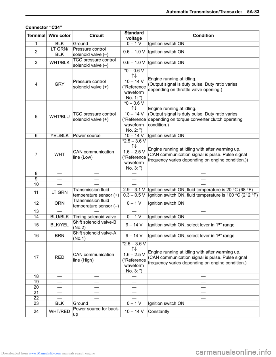
Connector βC34βTerminal Wire color Circuit Standard
voltage Condition
1 BLK Ground 0 β 1 V Ignition switch ON
2 LT GRN/
BLK Pressure control
solenoid valve (β)
0.6 β 1.0 V Ignition switch ON
3WHT/BLK TCC pressure control
solenoid valve (β) 0.6 β 1.0 V Ignition switch ON
4GRY Pressure control
solenoid valve (+) *0 β 0.6 V
ββ
10 β 14 V
(βReference waveform No. 1: β) Engine running at idling.
(Output signal is duty pulse. Duty ratio varies
depending on throttle valve opening.)
5WHT/BLU TCC pressure control
solenoid valve (+) *0 β 0.6 V
ββ
10 β 14 V
(βReference waveform No. 2: β) Engine running at idling.
(Output signal is duty pulse. Duty ratio varies
depending on torque converter clutch operating
condition.)
6 YEL/BLK Power source 10 β 14 V Ignition switch ON
7WHT CAN communication
line (Low) *2.5 β 3.6 V
ββ
1.6 β 2.5 V
(βReference waveform No. 3: β) Engine running at idling with after warming up.
(CAN communication signal is pulse. Pulse signal
frequency varies depending on engine condition.))
8β β β β
9β β β β
10 β ββ β
11 LT G R N Transmission fluid
temperature sensor (+) 2.9 β 3.1 V Ignition switch ON, fluid temperature is 20
Β°C (68 Β°F)
0.3 β 0.5 V Ignition switch ON, fluid temperature is 100 Β°C (212 Β°F)
12 ORN Transmission fluid
temperature sensor (β) 0 β 1 V Ignition switch ON
13 β ββ β
14 BLU/BLK Timing solenoid valv e 0 β 1 V Ignition switch ON
15 BLK/YEL Shift solenoid valve-B
(No.2) 9 β 14 V Ignition switch ON, select lever in βPβ range
16 BRN Shift solenoid valve-A
(No.1) 9 β 14 V Ignition switch ON, select lever in βPβ range
17 RED CAN communication
line (High) *2.5 β 3.6 V
ββ
1.6 β 2.5 V
(βReference waveform No. 3: β) Engine running at idling with after warming up.
(CAN communication signal is pulse. Pulse signal
frequency varies depending on engine condition.)
18 β ββ β
19 β ββ β
20 β ββ β
21 β ββ β
22 β ββ β
23 BLK Ground 0 β 1 V Ignition switch ON
24 WHT/RED Power source
for back-
up 10 β 14 V Constantly
Page 728 of 1496
Downloaded from www.Manualslib.com manuals search engine 5A-84 Automatic Transmission/Transaxle:
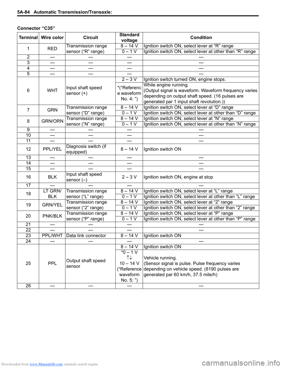
Connector βC35β
Terminal Wire color Circuit Standard
voltage Condition
1RED Transmission range
sensor (βRβ range) 8 β 14 V Ignition switch ON, select lever at βRβ range
0 β 1 V Ignition switch ON, select lever at other than βRβ range
2β β β β
3β β β β
4β β β β
5β β β β
6WHT Input shaft speed
sensor (+) 2 β 3 V Ignition switch turned ON, engine stops.
*(βReferenc
e waveform No. 4: β) While engine running.
(Output signal is waveform. Waveform frequency varies
depending on output shaft speed. (16 pulses are
generated par 1 input shaft revolution.))
7GRN Transmission range
sensor (βDβ range) 8 β 14 V Ignition switch ON, select lever at βDβ range
0 β 1 V Ignition switch ON, select lever at other than βDβ range
8 GRN/ORN Transmission range
sensor (βNβ range) 8 β 14 V Ignition switch ON, select lever at βNβ range
0 β 1 V Ignition switch ON, select lever at other than βNβ range
9β β β β
10 β β β β 11 β β β β
12 PPL/YEL Diagnosis switch (if
equipped) 8 β 14 V Ignition switch ON
13 β β β β
14 β β β β
15 β β β β
16 BLK Input shaft speed
sensor (β) 2 β 3 V Ignition switch ON, engine at stop
17 β β β β
18 LT G R N /
BLK Transmission range
sensor (βLβ range) 8 β 14 V Ignition switch ON, select lever at βLβ range
0 β 1 V Ignition switch ON, select lever at other than βLβ range
19 GRN/YEL Transmission range
sensor (β2β range) 8 β 14 V Ignition switch ON, select lever at β2β range
0 β 1 V Ignition switch ON, select lever at other than β2β range
20 PNK/BLK Transmission range
sensor (βPβ range) 8 β 14 V Ignition switch ON, select lever at βPβ range
0 β 1 V Ignition switch ON, select lever at other than βPβ range
21 β β β β
22 β β β β
23 PPL/WHT Data link connector 8 β 14 V Ignition switch ON
24 β β β β
25 PPL Output shaft speed
sensor 8 β 14 V Ignition switch ON
*0 β 1 V ββ
10 β 14 V
(βReference waveform No. 5: β) Vehicle running.
(Sensor signal is pulse. Pulse frequency varies
depending on vehicle speed. (8190 pulses are
generated par 60 km/h, 37.5 mile/h)
26 β β β β
Page 743 of 1496
Downloaded from www.Manualslib.com manuals search engine Automatic Transmission/Transaxle: 5A-99
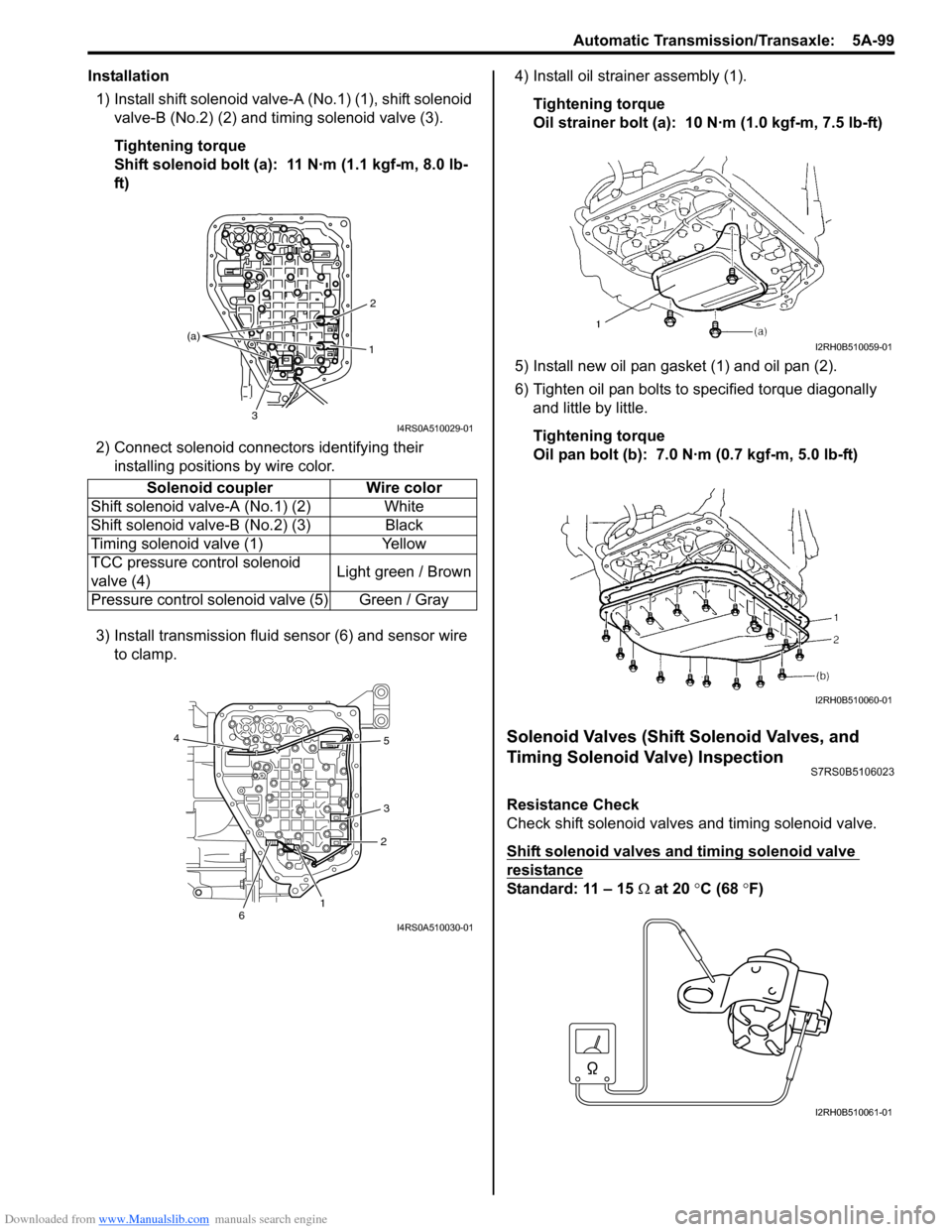
Installation1) Install shift solenoid valve- A (No.1) (1), shift solenoid
valve-B (No.2) (2) and timing solenoid valve (3).
Tightening torque
Shift solenoid bolt (a): 11 NΒ·m (1.1 kgf-m, 8.0 lb-
ft)
2) Connect solenoid connectors identifying their installing positions by wire color.
3) Install transmission fluid sensor (6) and sensor wire to clamp. 4) Install oil strain
er assembly (1).
Tightening torque
Oil strainer bolt (a): 10 NΒ·m (1.0 kgf-m, 7.5 lb-ft)
5) Install new oil pan gasket (1) and oil pan (2).
6) Tighten oil pan bolts to specified torque diagonally and little by little.
Tightening torque
Oil pan bolt (b): 7.0 NΒ·m (0.7 kgf-m, 5.0 lb-ft)
Solenoid Valves (Shift Solenoid Valves, and
Timing Solenoid Valve) Inspection
S7RS0B5106023
Resistance Check
Check shift solenoid valves and timing solenoid valve.
Shift solenoid valves and timing solenoid valve
resistance
Standard: 11 β 15 β¦ at 20 Β°C (68 Β° F)
Solenoid coupler Wire color
Shift solenoid valv e-A (No.1) (2) White
Shift solenoid valv e-B (No.2) (3) Black
Timing solenoid valve (1) Yellow
TCC pressure control solenoid
valve (4) Light green / Brown
Pressure control solenoid valve (5) Green / Gray
1 2
3
(a)
I4RS0A510029-01
1
2
3 5
4
6
I4RS0A510030-01
I2RH0B510059-01
I2RH0B510060-01
I2RH0B510061-01