Cable SUZUKI SWIFT 2008 2.G Service Workshop Manual
[x] Cancel search | Manufacturer: SUZUKI, Model Year: 2008, Model line: SWIFT, Model: SUZUKI SWIFT 2008 2.GPages: 1496, PDF Size: 34.44 MB
Page 975 of 1496
Downloaded from www.Manualslib.com manuals search engine Air Conditioning System: Manual Type 7B-27
A/C Switch InspectionS7RS0B7216014
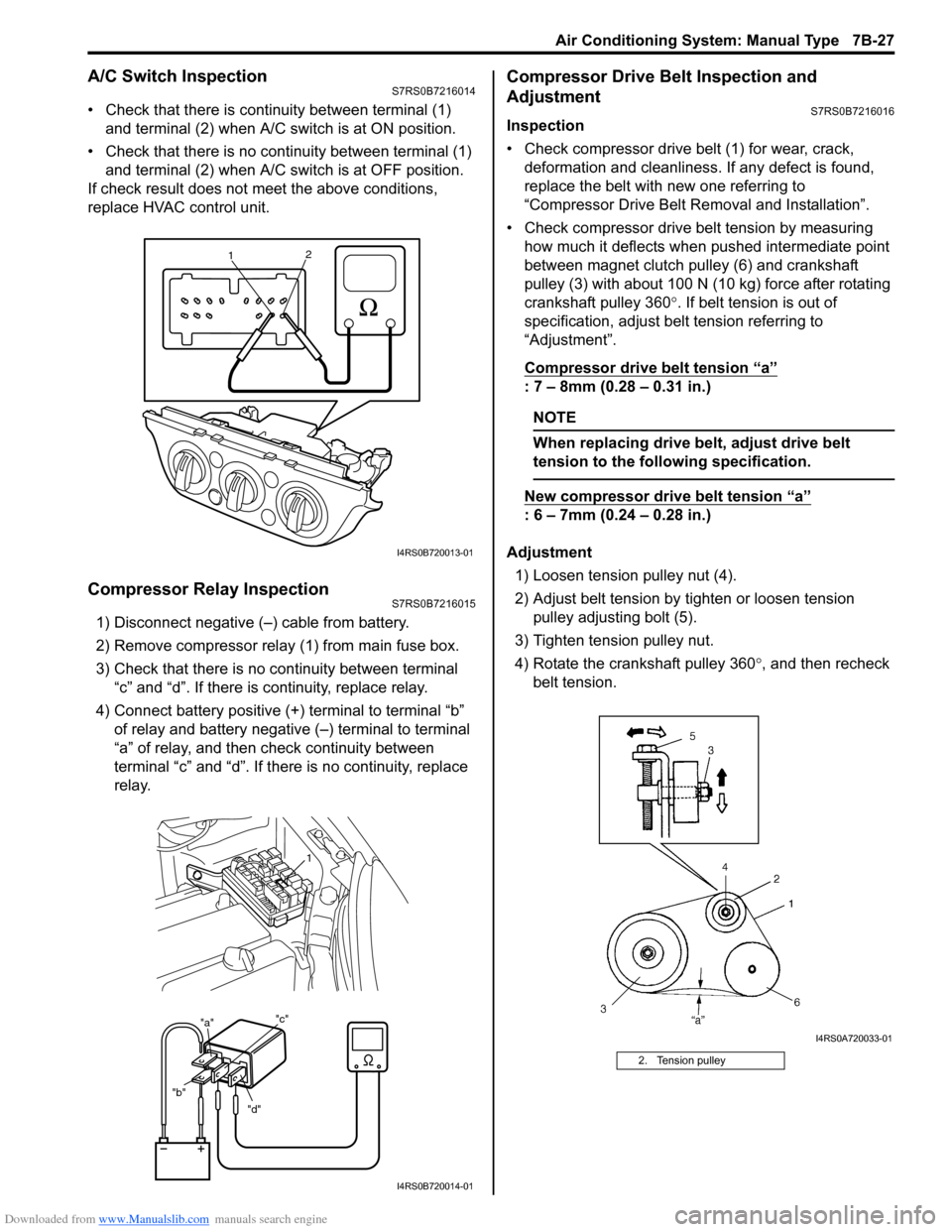
• Check that there is continuity between terminal (1) and terminal (2) when A/C s witch is at ON position.
• Check that there is no continuity between terminal (1) and terminal (2) when A/C s witch is at OFF position.
If check result does not meet the above conditions,
replace HVAC control unit.
Compressor Relay InspectionS7RS0B7216015
1) Disconnect negative (–) cable from battery.
2) Remove compressor relay (1) from main fuse box.
3) Check that there is no continuity between terminal “c” and “d”. If there is continuity, replace relay.
4) Connect battery positive (+ ) terminal to terminal “b”
of relay and battery negative (–) terminal to terminal
“a” of relay, and then check continuity between
terminal “c” and “d”. If there is no continuity, replace
relay.
Compressor Drive Belt Inspection and
Adjustment
S7RS0B7216016
Inspection
• Check compressor drive belt (1) for wear, crack, deformation and cleanliness. If any defect is found,
replace the belt with new one referring to
“Compressor Drive Belt Re moval and Installation”.
• Check compressor drive belt tension by measuring how much it deflects when pushed intermediate point
between magnet clutch pulley (6) and crankshaft
pulley (3) with about 100 N (10 kg) force after rotating
crankshaft pulley 360 °. If belt tension is out of
specification, adjust belt tension referring to
“Adjustment”.
Compressor drive belt tension
“a”
: 7 – 8mm (0.28 – 0.31 in.)
NOTE
When replacing drive belt, adjust drive belt
tension to the following specification.
New compressor dr ive belt tension “a”
: 6 – 7mm (0.24 – 0.28 in.)
Adjustment 1) Loosen tension pulley nut (4).
2) Adjust belt tension by ti ghten or loosen tension
pulley adjusting bolt (5).
3) Tighten tension pulley nut.
4) Rotate the crankshaft pulley 360 °, and then recheck
belt tension.
1 2
I4RS0B720013-01
"d"
"b" "a"
"c"
1
I4RS0B720014-01
2. Tension pulley
I4RS0A720033-01
Page 976 of 1496
Downloaded from www.Manualslib.com manuals search engine 7B-28 Air Conditioning System: Manual Type
Compressor Drive Belt Removal and
Installation
S7RS0B7216017
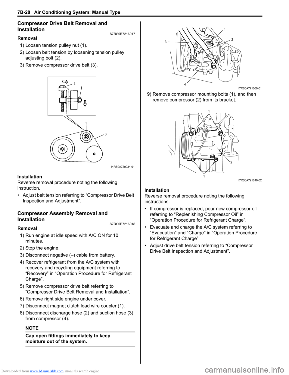
Removal1) Loosen tension pulley nut (1).
2) Loosen belt tension by loosening tension pulley adjusting bolt (2).
3) Remove compressor drive belt (3).
Installation
Reverse removal procedure noting the following
instruction.
• Adjust belt tension referring to “Compressor Drive Belt Inspection and Adjustment”.
Compressor Assembly Removal and
Installation
S7RS0B7216018
Removal
1) Run engine at idle speed with A/C ON for 10 minutes.
2) Stop the engine.
3) Disconnect negative (–) cable from battery.
4) Recover refrigerant fr om the A/C system with
recovery and recycling equipment referring to
“Recovery” in “Operation Procedure for Refrigerant
Charge”.
5) Remove compressor drive belt referring to “Compressor Drive Belt Re moval and Installation”.
6) Remove right side engine under cover.
7) Disconnect magnet clutch lead wire coupler (1).
8) Disconnect discharge hose (2) and suction hose (3) from compressor (4).
NOTE
Cap open fittings immediately to keep
moisture out of the system.
9) Remove compressor mounting bolts (1), and then remove compressor (2 ) from its bracket.
Installation
Reverse removal procedure noting the following
instructions.
• If compressor is replaced, pour new compressor oil referring to “Replenishi ng Compressor Oil” in
“Operation Procedure for Refrigerant Charge”.
• Evacuate and charge the A/C system referring to “Evacuation” and “Charge” in “Operation Procedure
for Refrigerant Charge”.
• Adjust drive belt tension referring to “Compressor Drive Belt Inspecti on and Adjustment”.
I4RS0A720034-01
3
4 2
1
I7RS0A721009-01
1
1 2
I7RS0A721010-02
Page 982 of 1496
Downloaded from www.Manualslib.com manuals search engine 7B-34 Air Conditioning System: Automatic Type
Automatic Type
Precautions
A/C System CautionS7RS0B7220001
Refer to “A/C System Caution”.
Precautions in Diagnosing TroubleS7RS0B7220002
• Do not disconnect couplers from HVAC control module, battery cable from battery, HVAC control module ground
wire harness from body or main fuse before confirming diagnostic information (diagnostic trouble code) stored in
HVAC control module memory.
• Diagnostic information (diagnostic trouble code) stored in HVAC control module can be checked by display of HVAC
control module. Also, it can be checked by using SU ZUKI scan tool. Before checking diagnostic information
(diagnostic trouble code), read this manual and operator's manual for SUZUKI scan tool to know how to read
diagnostic information (diagnostic trouble code).
• When trouble is diagnosed using diagnostic information (diagnostic trouble code) on display of HVAC control
module, keep in your mind that each diagnostic inform ation (diagnostic trouble code) has priority, and only
diagnostic information (diagnostic troub le code) which has the highest priority is indicated. Therefore, after
troubleshooting the malfunction, make sure if there exists any other diagnostic information (diagnostic trouble
code).
• Be sure to read “Precautions for Electrical Circuit Service in Section 00” before inspection.
Precautions on Servicing A/C SystemS7RS0B7220003
Refer to “Precautions on Servicing A/C System”.
General Description
Auto A/C System DescriptionS7RS0B7221001
The automatic type air conditioning system (auto A/C) is pr ovided with the function to automatically control the inside
air temperature, fan speed, air flow outl et direction and air intake position by HVAC control module in addition to
functions of the manual type air conditioning system (manua l A/C). Once the inside air temperature is set using the
temperature selector, HVAC control module automatically controls the inside air temperature at the constant level at all
times based on the inside air temperature, outside ai r temperature, amount of sunlight and engine coolant
temperature detected respectively by the inside air te mperature sensor, outside air temperature sensor, sunload
sensor and ECT sensor. At this time, “FULL AUTO A/ C” appears on the display of HVAC control module.
With the air intake selector pushed in the above state, it is possible to select any position of the air intake actuator.
Then, “FULL AUTO A/C” on the display changes to “AUTO A/C”.
Page 996 of 1496
Downloaded from www.Manualslib.com manuals search engine 7B-48 Air Conditioning System: Automatic Type
Description for Each Step
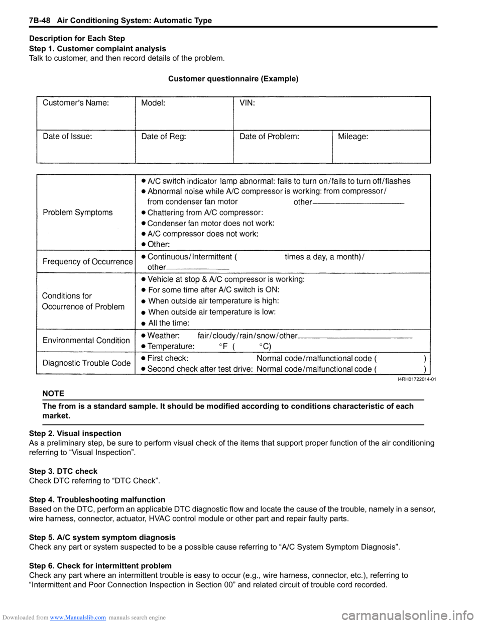
Step 1. Customer complaint analysis
Talk to customer, and then record details of the problem.
Customer questionnaire (Example)
NOTE
The from is a standard sample. It should be modified according to conditions characteristic of each
market.
Step 2. Visual inspection
As a preliminary step, be sure to perform visual check of th e items that support proper function of the air conditioning
referring to “Visual Inspection”.
Step 3. DTC check
Check DTC referring to “DTC Check”.
Step 4. Troubleshooting malfunction
Based on the DTC, perform an applicable DTC diagnostic flow and locate the cause of the trouble, namely in a sensor,
wire harness, connector, actuat or, HVAC control module or other part and repair faulty parts.
Step 5. A/C system symptom diagnosis
Check any part or system suspected to be a possible cause referring to “A/C System Symptom Diagnosis”.
Step 6. Check for intermittent problem
Check any part where an intermittent trouble is easy to oc cur (e.g., wire harness, connector, etc.), referring to
“Intermittent and Poor Connection Inspection in Sect ion 00” and related circuit of trouble cord recorded.
I4RH01722014-01
Page 1006 of 1496
Downloaded from www.Manualslib.com manuals search engine 7B-58 Air Conditioning System: Automatic Type
DTC Troubleshooting
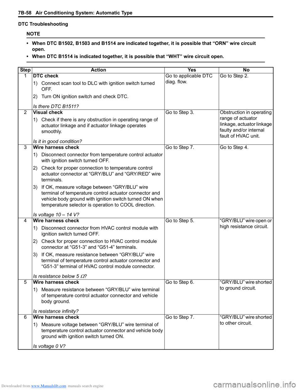
NOTE
• When DTC B1502, B1503 and B1514 are indicated together, it is possible that “ORN” wire circuit open.
• When DTC B1514 is indicated together, it is possible that “WHT” wire circuit open.
Step Action YesNo
1 DTC check
1) Connect scan tool to DLC with ignition switch turned
OFF.
2) Turn ON ignition switch and check DTC.
Is there DTC B1511? Go to applicable DTC
diag. flow.
Go to Step 2.
2 Visual check
1) Check if there is any obstruction in operating range of
actuator linkage and if actuator linkage operates
smoothly.
Is it in good condition? Go to Step 3.
Obstruction in operating
range of actuator
linkage, actuator linkage
faulty and/or internal
fault of HVAC unit.
3 Wire harness check
1) Disconnect connector from temperature control actuator
with ignition swit ch turned OFF.
2) Check for proper connection to temperature control actuator connector at “GRY /BLU” and “GRY/RED” wire
terminals.
3) If OK, measure voltage between “GRY/BLU” wire terminal of temperature control actuator connector and
vehicle body ground with ignition switch turned ON when
temperature selector is operation to COOL direction.
Is voltage 10 – 14 V? Go to Step 7.
Go to Step 4.
4 Wire harness check
1) Disconnect connector from HVAC control module with
ignition switch turned OFF.
2) Check for proper connection to HVAC control module connector at “G51-3” and “G51-4” terminals.
3) If OK, measure resistance between “GRY/BLU” wire terminal of temperature control actuator connector and
“G51-3” terminal of HVAC control module connector.
Is resistance below 5
Ω? Go to Step 5. “GRY/BLU” wire open or
high resistance circuit.
5 Wire harness check
1) Measure resistance between “GRY/BLU” wire terminal
of temperature control actuator connector and vehicle
body ground.
Is resistance infinity? Go to Step 6.
“GRY/BLU” wire shorted
to ground circuit.
6 Wire harness check
1) Measure voltage between “GRY/BLU” wire terminal of
temperature control actuator connector and vehicle body
ground with ignition switch turned ON.
Is voltage 0 V? Go to Step 7.
“GRY/BLU” wire shorted
to other circuit.
Page 1008 of 1496
Downloaded from www.Manualslib.com manuals search engine 7B-60 Air Conditioning System: Automatic Type
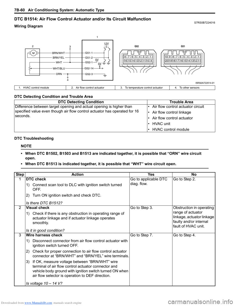
DTC B1514: Air Flow Control Actuator and/or Its Circuit MalfunctionS7RS0B7224016
Wiring Diagram
DTC Detecting Condition and Trouble Area
DTC Troubleshooting
NOTE
• When DTC B1502, B1503 and B1513 are indicated together, it is possible that “ORN” wire circuit open.
• When DTC B1513 is indicated together, it is possible that “WHT” wire circuit open.
7812910
65 431516 14 13 12 11
G52
789101920121112
65 431718 16 15 14 13
G51
M 12V
5V 5V
WHT/BLU
WHT
BRN/WHT
BRN/YEL
2
1
ORN
G51-1
G51-2
G52-1
G52-14
G52-3
3
4
I5RS0A722014-01
1. HVAC control module 2. Air flow control actuator3. To temperature control actuator 4. To other sensors
DTC Detecting Condition Trouble Area
Difference between target opening and actual opening is higher than
specified value even though air flow control actuator has operated for 16
seconds. • Air flow control actuator circuit
• Air flow control linkage
• Air flow control actuator
• HVAC unit
• HVAC control module
Step
Action YesNo
1 DTC check
1) Connect scan tool to DLC with ignition switch turned
OFF.
2) Turn ON ignition switch and check DTC.
Is there DTC B1512? Go to applicable DTC
diag. flow.
Go to Step 2.
2 Visual check
1) Check if there is any obstruction in operating range of
actuator linkage and if actuator linkage operates
smoothly.
Is it in good condition? Go to Step 3.
Obstruction in operating
range of actuator
linkage, actuator linkage
faulty and/or internal
fault of HVAC unit.
3 Wire harness check
1) Disconnect connector from air flow control actuator with
ignition switch turned OFF.
2) Check for proper connection to air flow control actuator
connector at “BRN/WHT” and “BRN/YEL” wire terminals.
3) If OK, measure voltage between “BRN/WHT” wire terminal of air flow control actuator connector and
vehicle body ground with ignition switch turned ON when
air flow selector is operation to DEF direction.
Is voltage 10 – 14 V? Go to Step 7.
Go to Step 4.
Page 1013 of 1496
Downloaded from www.Manualslib.com manuals search engine Air Conditioning System: Automatic Type 7B-65
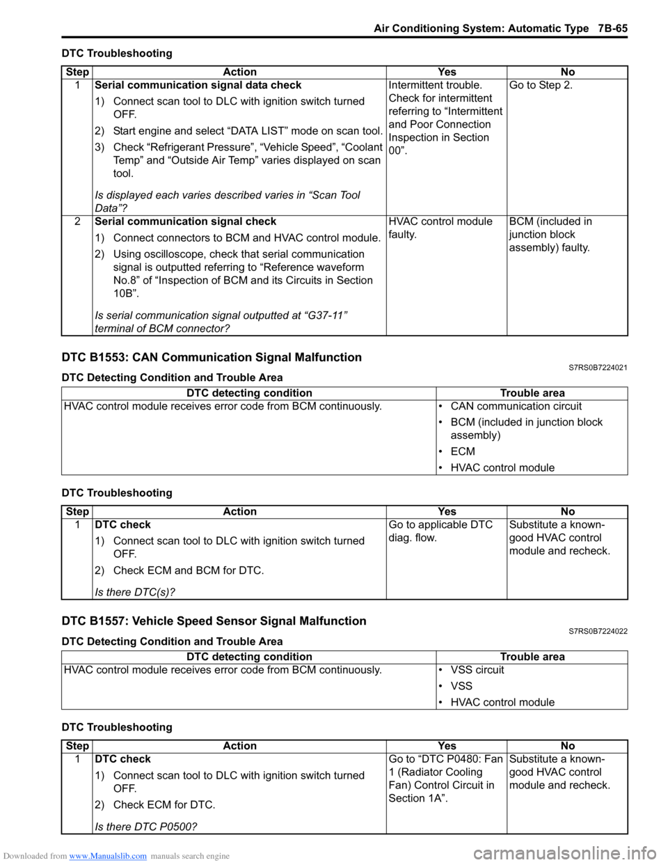
DTC Troubleshooting
DTC B1553: CAN Communication Signal MalfunctionS7RS0B7224021
DTC Detecting Condition and Trouble Area
DTC Troubleshooting
DTC B1557: Vehicle Speed Sensor Signal MalfunctionS7RS0B7224022
DTC Detecting Condition and Trouble Area
DTC TroubleshootingStep Action Yes No
1 Serial communication signal data check
1) Connect scan tool to DLC with ignition switch turned
OFF.
2) Start engine and select “DATA LIST” mode on scan tool.
3) Check “Refrigerant Pressure”, “Vehicle Speed”, “Coolant Temp” and “Outside Air Temp” varies displayed on scan
tool.
Is displayed each va ries described varies in “Scan Tool
Data”? Intermittent trouble.
Check for intermittent
referring to “Intermittent
and Poor Connection
Inspection in Section
00”.
Go to Step 2.
2 Serial communication signal check
1) Connect connectors to BCM and HVAC control module.
2) Using oscilloscope, check that serial communication
signal is outputted referring to “Reference waveform
No.8” of “Inspection of BCM and its Circuits in Section
10B”.
Is serial communication signal outputted at “G37-11”
terminal of BCM connector? HVAC control module
faulty.
BCM (included in
junction block
assembly) faulty.
DTC detecting condition
Trouble area
HVAC control module receives error code fr om BCM continuously.• CAN communication circuit
• BCM (included in junction block assembly)
•ECM
• HVAC control module
Step Action YesNo
1 DTC check
1) Connect scan tool to DLC with ignition switch turned
OFF.
2) Check ECM and BCM for DTC.
Is there DTC(s)? Go to applicable DTC
diag. flow.
Substitute a known-
good HVAC control
module and recheck.
DTC detecting condition
Trouble area
HVAC control module receives error code from BCM continuously. • VSS circuit
• VSS
• HVAC control module
Step Action YesNo
1 DTC check
1) Connect scan tool to DLC with ignition switch turned
OFF.
2) Check ECM for DTC.
Is there DTC P0500? Go to “DTC P0480: Fan
1 (Radiator Cooling
Fan) Control Circuit in
Section 1A”.
Substitute a known-
good HVAC control
module and recheck.
Page 1014 of 1496
Downloaded from www.Manualslib.com manuals search engine 7B-66 Air Conditioning System: Automatic Type
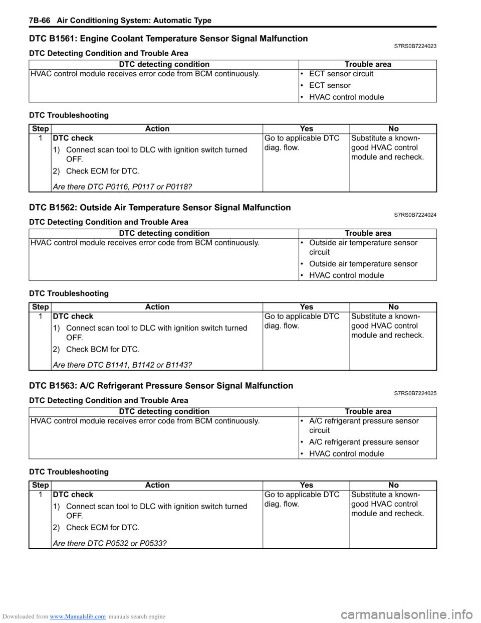
DTC B1561: Engine Coolant Temperature Sensor Signal MalfunctionS7RS0B7224023
DTC Detecting Condition and Trouble Area
DTC Troubleshooting
DTC B1562: Outside Air Temperature Sensor Signal MalfunctionS7RS0B7224024
DTC Detecting Condition and Trouble Area
DTC Troubleshooting
DTC B1563: A/C Refrigerant Pressure Sensor Signal MalfunctionS7RS0B7224025
DTC Detecting Condition and Trouble Area
DTC TroubleshootingDTC detecting condition Trouble area
HVAC control module receives error code from BCM continuously. • ECT sensor circuit
• ECT sensor
• HVAC control module
StepAction YesNo
1 DTC check
1) Connect scan tool to DLC with ignition switch turned
OFF.
2) Check ECM for DTC.
Are there DTC P0116, P0117 or P0118? Go to applicable DTC
diag. flow.
Substitute a known-
good HVAC control
module and recheck.
DTC detecting condition
Trouble area
HVAC control module receives er ror code from BCM continuously. • Outside air temperature sensor
circuit
• Outside air temperature sensor
• HVAC control module
Step Action YesNo
1 DTC check
1) Connect scan tool to DLC with ignition switch turned
OFF.
2) Check BCM for DTC.
Are there DTC B1141, B1142 or B1143? Go to applicable DTC
diag. flow.
Substitute a known-
good HVAC control
module and recheck.
DTC detecting condition
Trouble area
HVAC control module receives er ror code from BCM continuously. • A/C refrigerant pressure sensor
circuit
• A/C refrigerant pressure sensor
• HVAC control module
Step Action YesNo
1 DTC check
1) Connect scan tool to DLC with ignition switch turned
OFF.
2) Check ECM for DTC.
Are there DTC P0532 or P0533? Go to applicable DTC
diag. flow.
Substitute a known-
good HVAC control
module and recheck.
Page 1021 of 1496
Downloaded from www.Manualslib.com manuals search engine Air Conditioning System: Automatic Type 7B-73
HVAC Unit Removal and InstallationS7RS0B7226003
Refer to “HVAC Unit Removal and Installation”.
Temperature Control Actuator Removal and
Installation
S7RS0B7226004
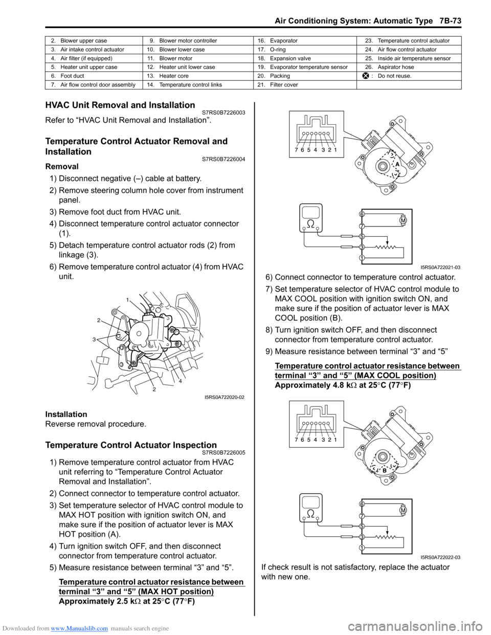
Removal1) Disconnect negative (–) cable at battery.
2) Remove steering column hol e cover from instrument
panel.
3) Remove foot duct from HVAC unit.
4) Disconnect temperature control actuator connector (1).
5) Detach temperature control actuator rods (2) from linkage (3).
6) Remove temperature control actuator (4) from HVAC unit.
Installation
Reverse removal procedure.
Temperature Control Actuator InspectionS7RS0B7226005
1) Remove temperature control actuator from HVAC unit referring to “Temperature Control Actuator
Removal and Installation”.
2) Connect connector to temperature control actuator.
3) Set temperature selector of HVAC control module to MAX HOT position with ignition switch ON, and
make sure if the position of actuator lever is MAX
HOT position (A).
4) Turn ignition switch OFF, and then disconnect connector from temperature control actuator.
5) Measure resistance between terminal “3” and “5”.
Temperature control actuator resistance between
terminal “3” and “5” (MAX HOT position)
Approximately 2.5 k Ω at 25 °C (77 °F) 6) Connect connector to tem
perature control actuator.
7) Set temperature selector of HVAC control module to MAX COOL position with ignition switch ON, and
make sure if the position of actuator lever is MAX
COOL position (B).
8) Turn ignition switch OFF, and then disconnect connector from temperature control actuator.
9) Measure resistance between terminal “3” and “5”
Temperature control actuator resistance between
terminal “3” and “5” (MAX COOL position)
Approximately 4.8 k Ω at 25 °C (77 °F)
If check result is not satisfactory, replace the actuator
with new one.
2. Blower upper case 9. Blower motor controller 16. Evaporator 23. Temperature control actuator
3. Air intake control actuator 10. Blower lower case 17. O-ring24. Air flow control actuator
4. Air filter (if equipped) 11. Blower motor 18. Expansion valve25. Inside air temperature sensor
5. Heater unit upper case 12. Heater unit lower case 19. Evaporator temperature sensor 26. Aspirator hose
6. Foot duct 13. Heater core 20. Packing : Do not reuse.
7. Air flow control door assembly 14. Temperature control links 21. Filter cover
1
2
2
3
4
I5RS0A722020-02
I5RS0A722021-03
I5RS0A722022-03
Page 1022 of 1496
Downloaded from www.Manualslib.com manuals search engine 7B-74 Air Conditioning System: Automatic Type
Air Flow Control Actuator Removal and
Installation
S7RS0B7226006
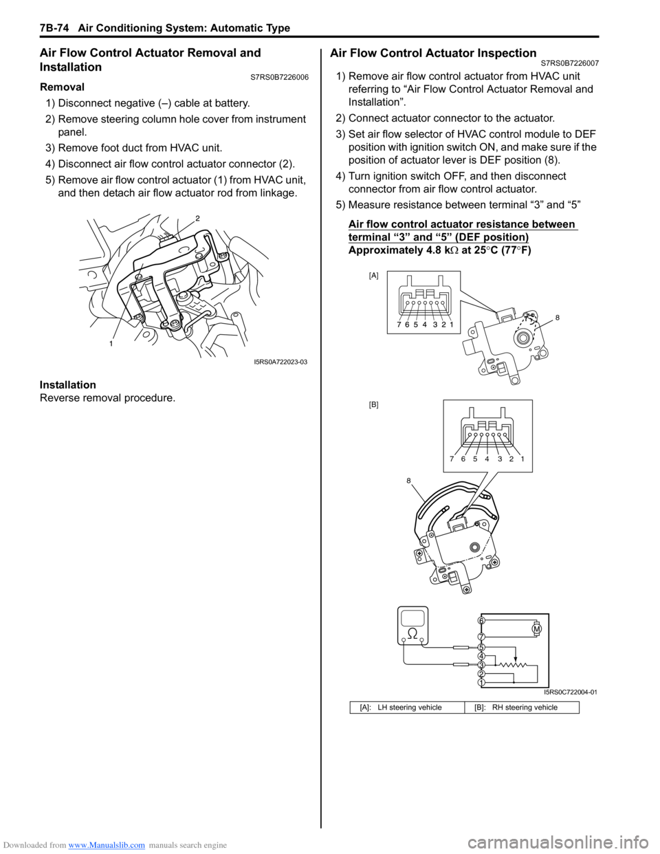
Removal1) Disconnect negative (–) cable at battery.
2) Remove steering column hol e cover from instrument
panel.
3) Remove foot duct from HVAC unit.
4) Disconnect air flow contro l actuator connector (2).
5) Remove air flow control actuator (1) from HVAC unit, and then detach air flow actuator rod from linkage.
Installation
Reverse removal procedure.
Air Flow Control Actuator InspectionS7RS0B7226007
1) Remove air flow control actuator from HVAC unit referring to “Air Flow C ontrol Actuator Removal and
Installation”.
2) Connect actuator connector to the actuator.
3) Set air flow selector of HVAC control module to DEF position with ignition switch ON, and make sure if the
position of actuator lever is DEF position (8).
4) Turn ignition switch OFF, and then disconnect connector from air flow control actuator.
5) Measure resistance between terminal “3” and “5”
Air flow control actuator resistance between
terminal “3” and “5” (DEF position)
Approximately 4.8 k Ω at 25 °C (77 °F)
I5RS0A722023-03
[A]: LH steering vehicle [B]: RH steering vehicle
8
[A]
[B]
8
7654 321
I5RS0C722004-01