Drive SUZUKI SWIFT 2008 2.G Service Workshop Manual
[x] Cancel search | Manufacturer: SUZUKI, Model Year: 2008, Model line: SWIFT, Model: SUZUKI SWIFT 2008 2.GPages: 1496, PDF Size: 34.44 MB
Page 995 of 1496
Downloaded from www.Manualslib.com manuals search engine Air Conditioning System: Automatic Type 7B-47
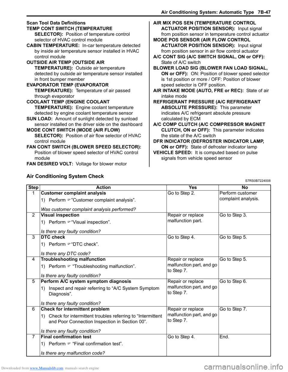
Scan Tool Data Definitions
TEMP CONT SWITCH (TEMPERATURE SELECTOR): Position of temperature control
selector of HVAC control module
CABIN TEMPERATURE: In-car temperature detected
by inside air temperature sensor installed in HVAC
control module
OUTSIDE AIR TEMP (OUTSIDE AIR TEMPERATURE): Outside air temperature
detected by outside air temperature sensor installed
in front bumper member
EVAPORATOR TEMP (EVAPORATOR TEMPERATURE): Temperature of air passed
through evaporator
COOLANT TEMP (ENGINE COOLANT TEMPERATURE): Engine coolant temperature
detected by engine coolant temperature sensor
SUN LOAD: Amount of sunlight detected by sunload
sensor installed on the driver side on the dashboard
MODE CONT SWITCH (MODE (AIR FLOW) SELECTOR): Position of air flow selector of HVAC
control module
FAN CONT SWITCH (BLOWER SPEED SELECTOR): Position of blower speed selector of HVAC control
module
FAN DESIRED VOLT: Voltage for blower motor AIR MIX POS SEN (TEMPERATURE CONTROL
ACTUATOR POSITI ON SENSOR): Input signal
from position sensor in temperature control actuator
MODE POS SENSOR (AIR FLOW CONTROL ACTUATOR POSITI ON SENSOR): Input signal
from position sensor in air flow control actuator
A/C CONT SIG (A/C SWITCH SIGNAL, ON or OFF): State of A/C switch
BLOWER LOAD SIG (BLO WER FAN LOAD SIGNAL,
ON or OFF): ON: Position of blower speed selector
is 1st position or more / OFF: Position of blower
speed selector is OFF position.
AIR INTAKE MODE (AUTO, FRE or REC): State of air
intake mode
REFRIGERANT PRESSURE (A/C REFRIGERANT ABSOLUTE PRESSURE): This parameter
indicates A/C refrigerant absolute pressure
calculated by ECM
A/C COMP CLUTCH (A/C COMPRESSOR MAGNET CLUTCH, ON or OFF): This parameter indicates
the state of the A/C switch
DFR INDICATOR (DEFROSTER INDICATOR LAMP, ON or OFF): State of defroster indicator lamp
VEHICLE SPEED: It is computed based on pulse
signals from vehicle speed sensor
Air Conditioning System CheckS7RS0B7224008
Step Action YesNo
1 Customer complaint analysis
1) Perform �)”Customer complaint analysis”.
Was customer complaint analysis performed? Go to Step 2.
Perform customer
complaint analysis.
2 Visual inspection
1) Perform �)“Visual inspection”.
Is there any faulty condition? Repair or replace
malfunction part.
Go to Step 3.
3 DTC check
1) Perform �)“DTC check”.
Is there any DTC code? Go to Step 4.
Go to Step 5.
4 Troubleshooting malfunction
1) Perform �) “Troubleshooting malfunction”.
Is there any faulty condition? Repair or replace
malfunction part, and go
to Step 7.
Go to Step 5.
5 Perform A/C system symptom diagnosis
1) Inspect and repair referri ng to “A/C System Symptom
Diagnosis”.
Is there any faulty condition? Repair or replace
malfunction part, and go
to Step 7.
Go to Step 6.
6 Check for intermittent problem
1) Check for intermittent troubles referring to “Intermittent
and Poor Connection Inspection in Section 00”.
Is there any faulty condition? Repair or replace
malfunction part, and go
to Step 7.
Go to Step 7.
7 Final confirmation test
1) Perform �) “Final confirmation test”.
Is there any malfunction code? Go to Step 4.
End.
Page 997 of 1496
Downloaded from www.Manualslib.com manuals search engine Air Conditioning System: Automatic Type 7B-49
Step 7. Final confirmation test
Confirm if the problem symptom is troubleshoot and the A/C system is free from any abnormal conditions. If there
existed DTC, clear the DTC. Then , check if the DTC is still detected and if there is any other DTC.
Visual InspectionS7RS0B7224009
Check visually the following parts and systems.
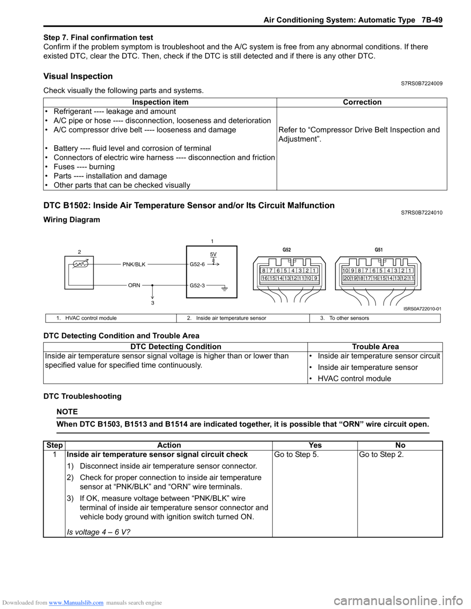
DTC B1502: Inside Air Temperature Sensor and/or Its Circuit MalfunctionS7RS0B7224010
Wiring Diagram
DTC Detecting Condition and Trouble Area
DTC Troubleshooting
NOTE
When DTC B1503, B1513 and B1514 are indicated together, it is possible that “ORN” wire circuit open.
Inspection item Correction
• Refrigerant ---- leakage and amount
• A/C pipe or hose ---- disconnection, looseness and deterioration
• A/C compressor drive belt ---- looseness and damage Refer to “Compressor Drive Belt Inspection and
Adjustment”.
• Battery ---- fluid level and corrosion of terminal
• Connectors of electric wire harn ess ---- disconnection and friction
• Fuses ---- burning
• Parts ---- installation and damage
• Other parts that can be checked visually
5V
PNK/BLK
ORN G52-6
G52-3
2
1
3
7812910
65 431516 14 13 12 11
G52
789101920121112
65 431718 16 15 14 13
G51
I5RS0A722010-01
1. HVAC control module
2. Inside air temperature sensor 3. To other sensors
DTC Detecting Condition Trouble Area
Inside air temperature sensor signal voltage is higher than or lower than
specified value for specified time continuously. • Inside air temperature sensor circuit
• Inside air temperature sensor
• HVAC control module
Step
Action YesNo
1 Inside air temperature sensor signal circuit check
1) Disconnect inside air temperature sensor connector.
2) Check for proper connection to inside air temperature
sensor at “PNK/BLK” and “ORN” wire terminals.
3) If OK, measure voltage between “PNK/BLK” wire terminal of inside air temp erature sensor connector and
vehicle body ground with ignition switch turned ON.
Is voltage 4 – 6 V? Go to Step 5.
Go to Step 2.
Page 1026 of 1496
Downloaded from www.Manualslib.com manuals search engine 7B-78 Air Conditioning System: Automatic Type
Inside Air Temperature Sensor Removal and
Installation
S7RS0B7226018
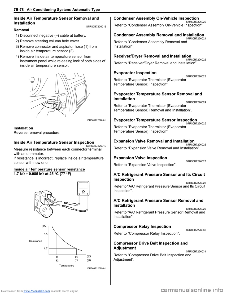
Removal1) Disconnect negative (–) cable at battery.
2) Remove steering column hole cover.
3) Remove connector and aspirator hose (1) from inside air temperature sensor (2).
4) Remove inside air temperature sensor from instrument panel while releas ing lock of both sides of
inside air temperature sensor.
Installation
Reverse removal procedure.
Inside Air Temperature Sensor InspectionS7RS0B7226019
Measure resistance between each connector terminal
with an ohmmeter.
If resistance is incorrect, replace inside air temperature
sensor with new one.
Inside air temperature sensor resistance
1.7 k Ω ± 0.085 k Ω at 25 °C (77 ° F)
Condenser Assembly On-Vehicle InspectionS7RS0B7226020
Refer to “Condenser Assembly On-Vehicle Inspection”.
Condenser Assembly Removal and InstallationS7RS0B7226021
Refer to “Condenser Assembly Removal and
Installation”.
Receiver/Dryer Removal and InstallationS7RS0B7226022
Refer to “Receiver/Dryer Removal and Installation”.
Evaporator InspectionS7RS0B7226023
Refer to “Evaporator Thermistor (Evaporator
Temperature Sensor) Inspection”.
Evaporator Temperature Sensor Removal and
Installation
S7RS0B7226024
Refer to “Evaporator Thermistor (Evaporator
Temperature Sensor) Removal and Installation”.
Evaporator Temperature Sensor InspectionS7RS0B7226025
Refer to “Evaporator Thermistor (Evaporator
Temperature Sensor) Inspection”.
Expansion Valve Removal and InstallationS7RS0B7226026
Refer to “Expansion Valve Removal and Installation”.
Expansion Valve InspectionS7RS0B7226027
Refer to “Expansion Valve Inspection”.
A/C Refrigerant Pressure Sensor and Its Circuit
Inspection
S7RS0B7226028
Refer to “A/C Refrigerant Pressure Sensor and Its Circuit
Inspection”.
A/C Refrigerant Pressure Sensor Removal and
Installation
S7RS0B7226029
Refer to “A/C Refrigerant Pressure Sensor Removal and
Installation”.
Compressor Relay InspectionS7RS0B7226030
Refer to “Compressor Relay Inspection”.
Compressor Drive Belt Inspection and
Adjustment
S7RS0B7226031
Refer to “Compressor Drive Belt Inspection and
Adjustment”.
12I5RS0A722028-01
Temperature
Resistance
1.7
0
32 25
77
F
5.5
I5RS0A722029-01
Page 1027 of 1496
Downloaded from www.Manualslib.com manuals search engine Air Conditioning System: Automatic Type 7B-79
Compressor Drive Belt Removal and
Installation
S7RS0B7226032
Refer to “Compressor Drive Belt Removal and
Installation”.
Compressor Assembly Removal and
Installation
S7RS0B7226033
Refer to “Compressor Assembly Removal and
Installation”.
Compressor Assembly ComponentsS7RS0B7226034
Refer to “Compressor Assembly Components”.
Magnet Clutch Removal and InstallationS7RS0B7226035
Refer to “Magnet Clutch Removal and Installation”.
Magnet Clutch InspectionS7RS0B7226036
Refer to “Magnet Clutch Inspection”.
Relief Valve InspectionS7RS0B7226039
Refer to “Relief Valve Inspection”.
Special Tools and Equipment
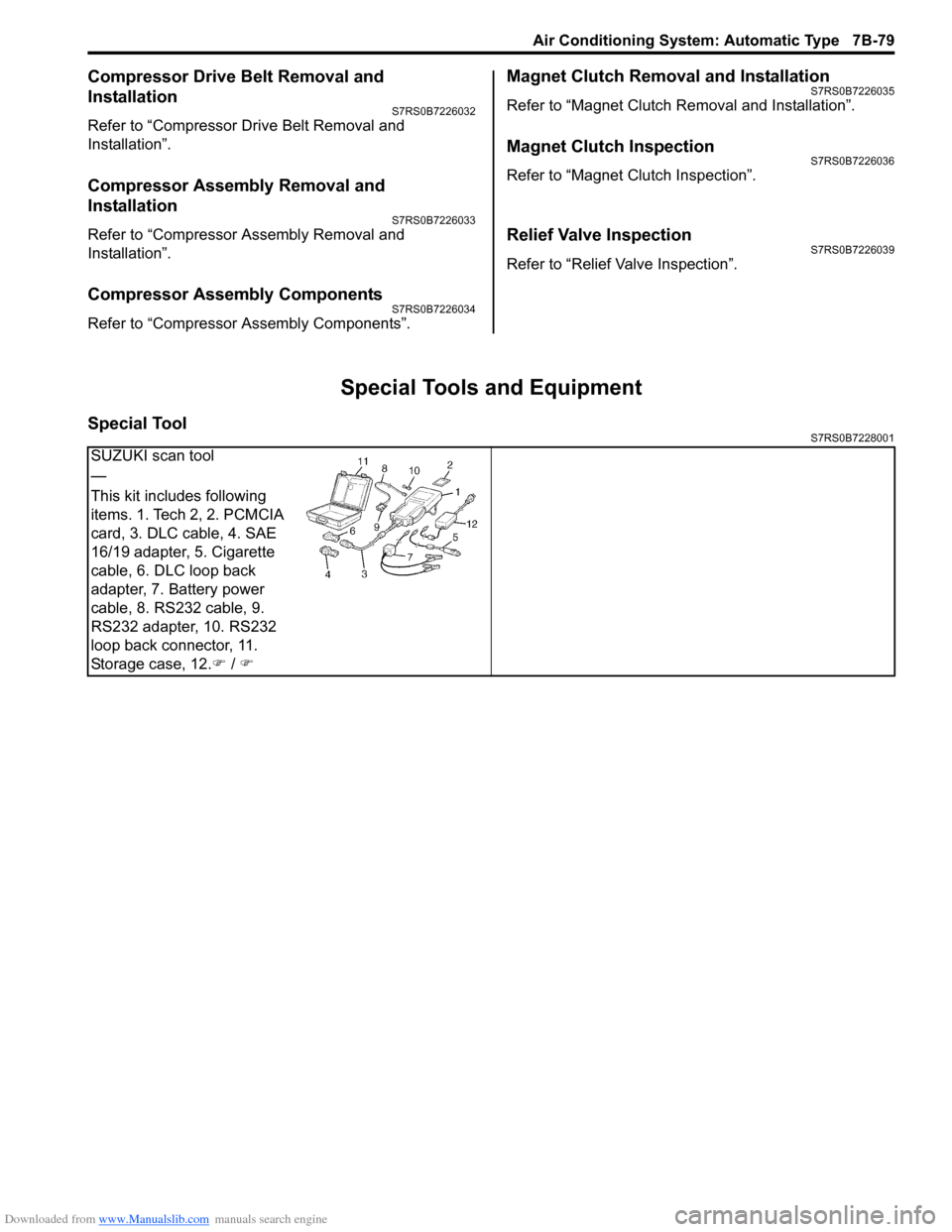
Special ToolS7RS0B7228001
SUZUKI scan tool
—
This kit includes following
items. 1. Tech 2, 2. PCMCIA
card, 3. DLC cable, 4. SAE
16/19 adapter, 5. Cigarette
cable, 6. DLC loop back
adapter, 7. Battery power
cable, 8. RS232 cable, 9.
RS232 adapter, 10. RS232
loop back connector, 11.
Storage case, 12.�) / �)
Page 1029 of 1496
Downloaded from www.Manualslib.com manuals search engine Table of Contents 8- i
8
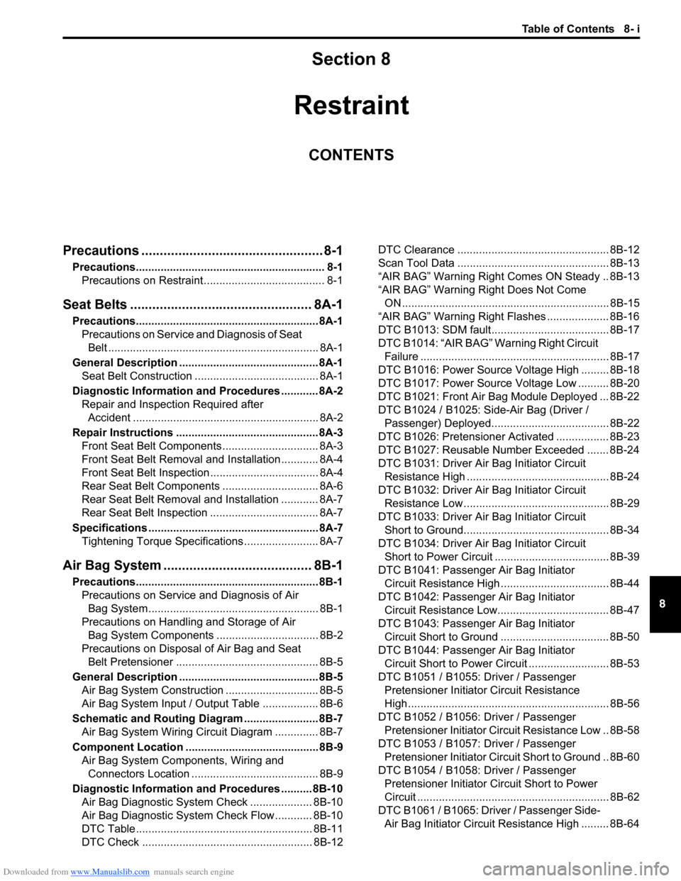
Section 8
CONTENTS
Restraint
Precautions ................................................. 8-1
Precautions............................................................. 8-1
Precautions on Restraint ....................................... 8-1
Seat Belts .......... ............................... ........ 8A-1
Precautions........................................................... 8A-1
Precautions on Service a nd Diagnosis of Seat
Belt .................................................................... 8A-1
General Description ............................................. 8A-1 Seat Belt Construction ........................................ 8A-1
Diagnostic Information and Procedures ............ 8A-2 Repair and Inspection Required after Accident ............................................................ 8A-2
Repair Instructions .............................................. 8A-3 Front Seat Belt Components ............................... 8A-3
Front Seat Belt Removal and Installation ............ 8A-4
Front Seat Belt Inspection ................................... 8A-4
Rear Seat Belt Components ............................... 8A-6
Rear Seat Belt Removal and Installation ............ 8A-7
Rear Seat Belt Inspection ................................... 8A-7
Specifications ....................................................... 8A-7
Tightening Torque Specifications ........................ 8A-7
Air Bag System ............... ......................... 8B-1
Precautions........................................................... 8B-1
Precautions on Service and Diagnosis of Air Bag System....................................................... 8B-1
Precautions on Handling and Storage of Air Bag System Components . ................................ 8B-2
Precautions on Disposal of Air Bag and Seat
Belt Pretensioner .............................................. 8B-5
General Description ............................................. 8B-5 Air Bag System Construction .............................. 8B-5
Air Bag System Input / Output Table .................. 8B-6
Schematic and Routing Diagram ........................ 8B-7 Air Bag System Wiring Circuit Diagram .............. 8B-7
Component Locatio n ........................................... 8B-9
Air Bag System Components, Wiring and Connectors Location ......................................... 8B-9
Diagnostic Information and Procedures .......... 8B-10 Air Bag Diagnostic System Check .................... 8B-10
Air Bag Diagnostic System Check Flow ............ 8B-10
DTC Table ......................................................... 8B-11
DTC Check ....................................................... 8B-12 DTC Clearance ................................................. 8B-12
Scan Tool Data ................................................. 8B-13
“AIR BAG” Warning Right Comes ON Steady .. 8B-13
“AIR BAG” Warning Right Does Not Come
ON ................................................................... 8B-15
“AIR BAG” Warning Right Flashes .................... 8B-16
DTC B1013: SDM fault...................................... 8B-17
DTC B1014: “AIR BAG” Warning Right Circuit Failure ............................................................. 8B-17
DTC B1016: Power Source Voltage High ......... 8B-18
DTC B1017: Power Source Voltage Low .......... 8B-20
DTC B1021: Front Air Bag Module Deployed ... 8B-22
DTC B1024 / B1025: Side-Air Bag (Driver / Passenger) Deployed...................................... 8B-22
DTC B1026: Pretensioner Activated ................. 8B-23
DTC B1027: Reusable Number Exceeded ....... 8B-24
DTC B1031: Driver Air Bag Initiator Circuit
Resistance High .............................................. 8B-24
DTC B1032: Driver Air Bag Initiator Circuit
Resistance Low ............................................... 8B-29
DTC B1033: Driver Air Bag Initiator Circuit
Short to Ground............................................... 8B-34
DTC B1034: Driver Air Bag Initiator Circuit
Short to Power Circuit .... ................................. 8B-39
DTC B1041: Passenger Air Bag Initiator Circuit Resistance High ................................... 8B-44
DTC B1042: Passenger Air Bag Initiator Circuit Resistance Low.................................... 8B-47
DTC B1043: Passenger Air Bag Initiator Circuit Short to Ground ................................... 8B-50
DTC B1044: Passenger Air Bag Initiator Circuit Short to Power Circ uit .......................... 8B-53
DTC B1051 / B1055: Driver / Passenger Pretensioner Initiator Circuit Resistance
High ................................................................. 8B-56
DTC B1052 / B1056: Driver / Passenger Pretensioner Initiator Circu it Resistance Low .. 8B-58
DTC B1053 / B1057: Driver / Passenger Pretensioner Initiator Circuit Short to Ground .. 8B-60
DTC B1054 / B1058: Driver / Passenger Pretensioner Initiator Circuit Short to Power
Circuit .............................................................. 8B-62
DTC B1061 / B1065: Driver / Passenger Side- Air Bag Initiator Circuit Resistance High ......... 8B-64
Page 1030 of 1496
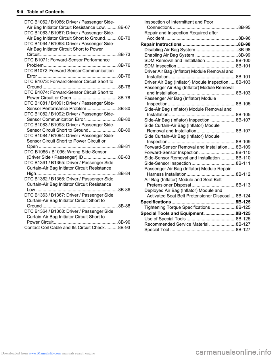
Downloaded from www.Manualslib.com manuals search engine 8-ii Table of Contents
DTC B1062 / B1066: Driver / Passenger Side-Air Bag Initiator Circuit Resistance Low .......... 8B-67
DTC B1063 / B1067: Driver / Passenger Side- Air Bag Initiator Circuit S hort to Ground .......... 8B-70
DTC B1064 / B1068: Driver / Passenger Side- Air Bag Initiator Circu it Short to Power
Circuit .............................................................. 8B-73
DTC B1071: Forward-Sensor Performance Problem ........................................................... 8B-76
DTC B1072: Forward-Sensor Communication Error ................................................................ 8B-76
DTC B1073: Forward-Sensor Circuit Short to Ground ............................................................ 8B-76
DTC B1074: Forward-Sensor Circuit Short to Power Circuit or Open ..................................... 8B-78
DTC B1081 / B1091: Driver / Passenger Side- Sensor Performance Probl em ......................... 8B-80
DTC B1082 / B1092: Driver / Passenger Side- Sensor Communication Erro r .......................... 8B-80
DTC B1083 / B1093: Driver / Passenger Side- Sensor Circuit Short to Ground ....................... 8B-80
DTC B1084 / B1094: Driver / Passenger Side- Sensor Circuit Short to Power Circuit or
Open ............................................................... 8B-81
DTC B1085 / B1095: Wrong Side-Sensor (Driver Side / Passenger) ID ........................... 8B-83
DTC B1361 / B1365: Driver / Passenger Side Curtain-Air Bag Initiator Circuit Resistance
High ................................................................. 8B-84
DTC B1362 / B1366: Driver / Passenger Side Curtain-Air Bag Initiator Circuit Resistance
Low ................................................................. 8B-86
DTC B1363 / B1367: Driver / Passenger Side Curtain-Air Bag Initiator Circuit Short to
Ground ............................................................ 8B-88
DTC B1364 / B1368: Driver / Passenger Side Curtain-Air Bag Initiator Circuit Short to
Power Circuit ................................................... 8B-90
Contact Coil Cable and Its Circuit Check .......... 8B-93 Inspection of Intermittent and Poor
Connections .................................................... 8B-95
Repair and Inspection Required after Accident .......................................................... 8B-96
Repair Instructions ............ ................................8B-98
Disabling Air Bag System.................................. 8B-98
Enabling Air Bag System .................................. 8B-99
SDM Removal and Installation ........................ 8B-100
SDM Inspection ............................................... 8B-101
Driver Air Bag (Inflato r) Module Removal and
Installation ..................................................... 8B-101
Driver Air Bag (Inflator) Module Inspection ..... 8B-103
Passenger Air Bag (Inflator) Module Removal and Installation .............................................. 8B-103
Passenger Air Bag (I nflator) Module
Inspection ...................................................... 8B-105
Side-Air Bag (Inflator) Module Removal and
Installation ..................................................... 8B-105
Side-Air Bag (Inflator) Inspection .................... 8B-107
Side Curtain-Air Bag (Inflator) Module Removal and Installation ............................... 8B-107
Side Curtain-Air Bag (Inflator) Module Inspection ...................................................... 8B-109
Forward-Sensor Removal and Installation ...... 8B-109
Forward-Sensor In spection ............................. 8B-110
Side-Sensor Removal and Installation ............ 8B-110
Side-Sensor Inspection ................................... 8B-111
Passenger Air Bag (Inflator) Module Repair
Harness Installation....................................... 8B-112
Air Bag (Inflator) Module and Seat Belt Pretensioner Disposal ................................... 8B-113
Deployed Air Bag (Inflator) Module and Activated Seat Belt Pretensioner Disposal.... 8B-124
Specifications .................. .................................8B-125
Tightening Torque Specifications .................... 8B-125
Special Tools and Equipmen t .........................8B-125
Use of Special Tools ....................................... 8B-125
Recommended Service Material ..................... 8B-127
Special Tool .................................................... 8B-127
Page 1033 of 1496
Downloaded from www.Manualslib.com manuals search engine Seat Belts: 8A-2
Seat Belt with ELR
The seat belt with emergency locking retractor (ELR) is
designed so that it locks immediately (to prevent the
webbing from being pulled out of the retractor any
further) when any of the following items is detected as
exceeding each set value;
• Speed at which the webbing is pulled out of the retractor.
• Acceleration or deceleration of the vehicle speed.
• Inclination.
Seat Belt with A-ELR
The automatic and emergency locking retractor (A-ELR)
works as an Emergency Locking Retractor (ELR) till its
webbing is pulled all the way out and then on as an
Automatic Locking Retractor (ALR ) till it is retracted fully.
ALR: Automatically locks when the webbing is pulled out
from the retractor and allowed to retract even a little.
Then the webbing can not be pulled out any further,
unless it is wound all the way back into the retractor,
which releases the lock and allows the webbing to be
pulled out.
Seat Belt with ELR and Pretensioner
The seat belt with ELR and a pretensioner has a
pretensioner mechanism whic h operates in linkage with
the air bag in addition to the described ELR.
The pretensioner is incorporated in retractor assembly
and controlled by SDM as one of air bag system
components. It will be activated at the same time as the
driver and passenger air bag module when an impact at
the front of vehicle exceeds the specified value.
When servicing seat belt (retractor assembly) with
pretensioner, be sure to observe all WARNINGS and
CAUTIONS and “Precautions on Service and Diagnosis
of Air Bag System in Section 8B”. CAUTION!
Do not reuse the seat belt pretensioner
(retractor assembly) that has activated.
Replace it with a new seat belt assembly and
buckle together as a set. For checking
procedure of its activation, refer to “Repair
and Inspection Required after Accident in
Section 8B”.
Seat Belt Remainder
When driver’s seat belt is unfastened (under the
following conditions), seat belt reminder light and
warning buzzer inform that driver’s seat belt is
unfastened. Seat belt reminder light located in
combination meter and warning buzzer located inside
BCM operate as follows:
• Seat belt reminder light comes on when driver’s seat belt is unfastened while igni tion key switch is at ON
position.
• If vehicle speed exceeds 15 km/h with seat belt unfastened, warning buzzer operates for
approximately 95 seconds and seat belt reminder light
flashes synchronously with buzzer. When warning
buzzer stops operating, seat belt reminder light is
turned on.
• If driver’s seat belt state is changed from “fastened” to “unfastened” while vehicle speed is above 15 km/h,
warning buzzer operates for approximately 95
seconds and seat belt reminder light flashes
synchronously with buzzer. When warning buzzer
stops operating, seat belt reminder light is turned on.
Diagnostic Information and Procedures
Repair and Inspection Required after AccidentS7RS0B8104001
After an accident, whether the seat belt pretensioner has been activated or not, be sure to perform checks and repairs
described on “Repair and Inspection Required after Accident in Section 8B”.
Page 1036 of 1496
Downloaded from www.Manualslib.com manuals search engine 8A-5 Seat Belts:
Seat Belt
• The seat belt webbing or strap should be free from damage.
Retractor Assembly (with Seat Belt Pretensioner) 1) Let the seat belt retract fully to confirm its easy retraction.
• The retractor assembly should lock webbing when
pulled quickly.
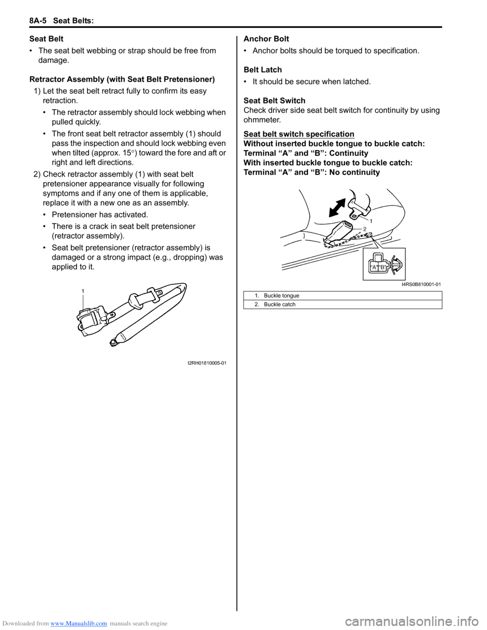
• The front seat belt retractor assembly (1) should pass the inspection and should lock webbing even
when tilted (approx. 15 °) toward the fore and aft or
right and left directions.
2) Check retractor assembly (1) with seat belt pretensioner appearance visually for following
symptoms and if any one of them is applicable,
replace it with a new one as an assembly.
• Pretensioner has activated.
• There is a crack in seat belt pretensioner (retractor assembly).
• Seat belt pretensioner (retractor assembly) is damaged or a strong impact (e.g., dropping) was
applied to it. Anchor Bolt
• Anchor bolts should be torqued to specification.
Belt Latch
• It should be secure when latched.
Seat Belt Switch
Check driver side seat belt s
witch for continuity by using
ohmmeter.
Seat belt switch specification
Without inserted buckle tongue to buckle catch:
Terminal “A” and “B”: Continuity
With inserted buckle tongue to buckle catch:
Terminal “A” and “B”: No continuity
I2RH01810005-01
1. Buckle tongue
2. Buckle catch
I4RS0B810001-01
Page 1039 of 1496
Downloaded from www.Manualslib.com manuals search engine Air Bag System: 8B-1
Restraint
Air Bag System
Precautions
Precautions on Service and Diagnosis of Air
Bag System
S7RS0B8200001
WARNING!
• If the air bag system and another vehicle system both need repair, SUZUKI
recommends that the air bag system be
repaired first, to help avoid unintended air
bag system activation.
• Do not modify the steering wheel, dashboard, both front seat or any other on
or around air bag system components.
Modifications can adversely affect air bag
system performance and lead to injury.
• Be sure to follow the procedures described in this section. Failure to follow
procedures could result in possible air bag
system activation, personal injury or
unneeded air bag system repairs.
• WARNING / CAUTION labels are attached on each
part of air bag system components (SDM, air bag
(inflator) modules and seat belt pretensioners). Be
sure to follow the instructions.
• Many of service procedures require disconnection of
“A/BAG” fuse and air bag (inflator) module(s) (driver,
passenger, side of both si des and curtain of both
sides) from initiator circuit to avoid an accidental
deployment.
• Do not apply power to the air bag system unless all components are connected or a diagnostic flow
requests it, as this will set a DTC.
• The “Air Bag Diagnostic S ystem Check” must be the
starting point of any air bag diagnostics. The “Air Bag
Diagnostic System Check” will verify proper “AIR
BAG” warning right operatio n and will lead you to the
correct flow to diagnose any air bag malfunctions.
Bypassing these procedures may result in extended
diagnostic time, incorrect diagnosis, and incorrect
parts replacements. • Never use air bag component parts from another
vehicle.
• If the vehicle will be exposed to temperatures over 93
° C (200 °F) (for example, during a paint baking
process), remove the air bag system components
beforehand to avoid component damage or
unintended system activation.
• When handling the air bag (inflator) modules (driver, passenger, side of both si des and curtain of both
sides), seat belt pretensio ners (driver and passenger),
SDM, forward-sensor or side-sensor, be careful not to
drop it or apply an impact to it. If an excessive impact
was applied (e.g., SDM, forward-sensor and side-
sensor are dropped, air bag (inflator) module is
dropped from a height of 90 cm (3 ft) or more, seat
belt pretensioner (retractor assembly) is dropped from
a height of 30 cm (1 ft) or more), never attempt
disassembly or repair but replace it with a new one.
• When using electric welding, be sure to disconnect air bag (inflator) module connectors (driver, passenger,
side of both sides and curtain of both sides) and seat
belt pretensioner connectors (driver and passenger)
respectively.
• When applying paint around the air bag system related parts, use care so that the harness or
connector will not be expo sed to the paint mist.
• Never expose air bag system component parts directly to hot air (drying or baking the vehicle after
painting) or flames.
WARNING!
When performing service on or around air
bag system components or air bag wiring,
follow the procedures listed in “Disabling Air
Bag System” to temporarily disable the air
bag system.
Failure to follow procedures could result in
possible air bag system activation, personal
injury or unneeded air bag system repairs.
Page 1040 of 1496
Downloaded from www.Manualslib.com manuals search engine 8B-2 Air Bag System:
Precautions on Handling and Storage of Air Bag
System Components
S7RS0B8200002
SDM
WARNING!
Never power up air bag system when SDM is
not rigidly attached to the vehicle. Otherwise,
personal injury may result.
CAUTION!
After detecting one time of such collision as
to meet deployment conditions, SDM must
not be used. Refer to “Air Bag Diagnostic
System Check” when checking SDM.
• Never attempt disassembly of SDM.
• When storing SDM, select a place where neither high temperature nor high humidity is anticipated and oil,
water and dust are kept off.
• If SDM has been dropped, replace it with a new one.
• If SDM installation part of floor was damaged, repair that part completely before reinstallation.
• All SDM and mounting bracket fasteners must be carefully torqued and the arrow must be pointed
toward the front of the vehicle to ensure proper
operation of the air bag system. Live (Undeployed) Air Bag (Inflator) Modules
Special care is necessary when handling and storing a
live (undeployed) air bag (inflator) modules.
The rapid gas generation produced during deployment
of the air bag could cause the air bag (inflator) module,
or an object in front of the air bag (inflator) module, to be
thrown through the air in the unlikely event of an
accidental deployment.
WARNING!
Never attempt to measure the resistance of
the air bag (inflator) modules (driver,
passenger and side of both sides and curtain
of both sides). It is
very dangerous as the
electric current from the tester may deploy
the air bag.
I5RH01820001-01
I4RS0A820001-03