306 SUZUKI SWIFT 2008 2.G Service Owner's Manual
[x] Cancel search | Manufacturer: SUZUKI, Model Year: 2008, Model line: SWIFT, Model: SUZUKI SWIFT 2008 2.GPages: 1496, PDF Size: 34.44 MB
Page 525 of 1496
Downloaded from www.Manualslib.com manuals search engine Rear Brakes: 4C-1
Brakes
Rear Brakes
Repair Instructions
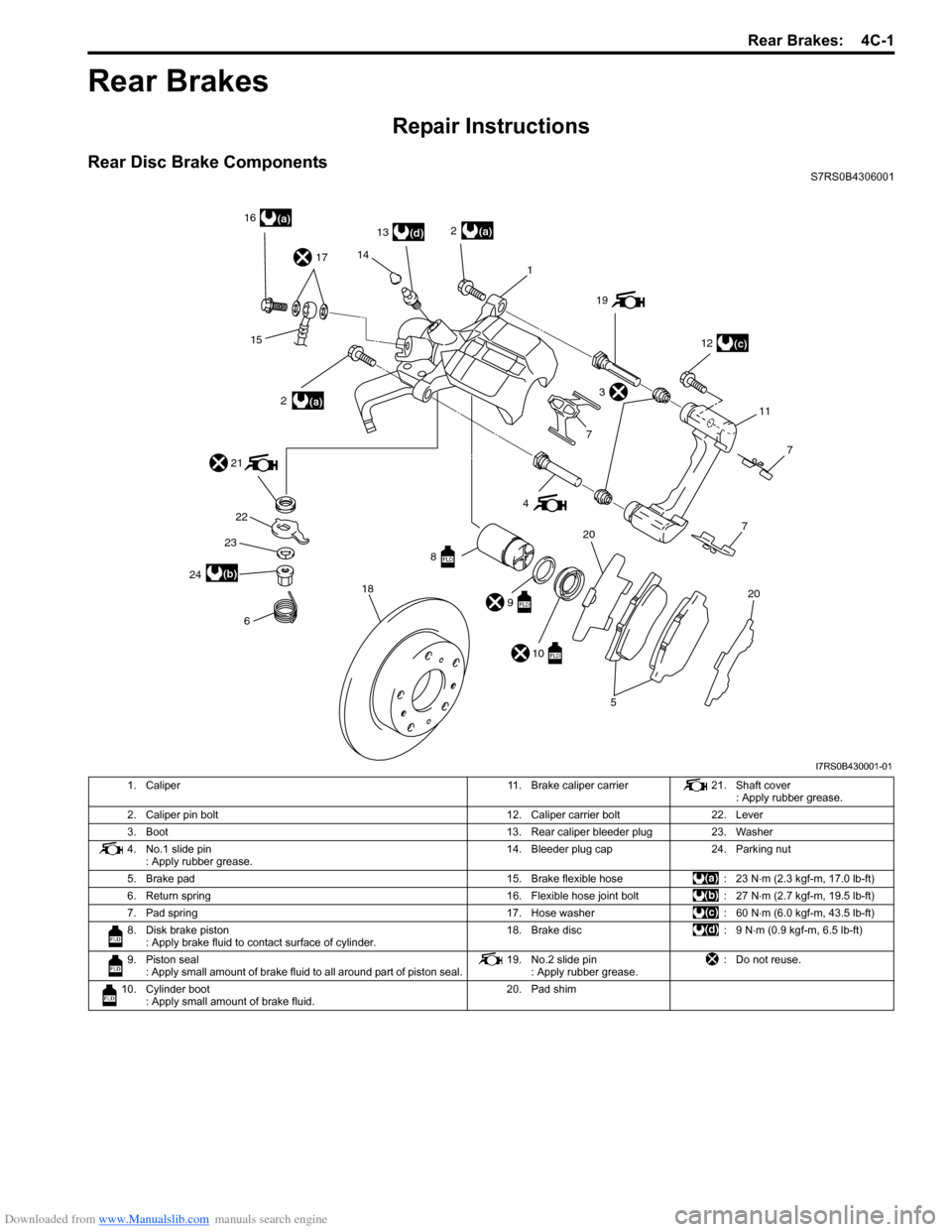
Rear Disc Brake ComponentsS7RS0B4306001
(d)
(c)
(a)
(a)
(a)16171413
2
1
15 2 19
12
117
7
3
7
4
20 20
5
10
9
8
(b)
18
6
24
23
22
21
I7RS0B430001-01
1. Caliper
11. Brake caliper carrier21. Shaft cover
: Apply rubber grease.
2. Caliper pin bolt 12. Caliper carrier bolt22. Lever
3. Boot 13. Rear caliper bleeder plug23. Washer
4. No.1 slide pin : Apply rubber grease. 14. Bleeder plug cap
24. Parking nut
5. Brake pad 15. Brake flexible hose: 23 N⋅m (2.3 kgf-m, 17.0 lb-ft)
6. Return spring 16. Flexible hose joint bolt: 27 N⋅m (2.7 kgf-m, 19.5 lb-ft)
7. Pad spring 17. Hose washer: 60 N⋅m (6.0 kgf-m, 43.5 lb-ft)
8. Disk brake piston : Apply brake fluid to contact surface of cylinder. 18. Brake disc
: 9 N⋅m (0.9 kgf-m, 6.5 lb-ft)
9. Piston seal : Apply small amount of brake fluid to all around part of piston seal. 19. No.2 slide pin
: Apply rubber grease. : Do not reuse.
10. Cylinder boot : Apply small amount of brake fluid. 20. Pad shim
Page 526 of 1496
Downloaded from www.Manualslib.com manuals search engine 4C-2 Rear Brakes:
Rear Disc Brake Pad Removal and InstallationS7RS0B4306002
NOTE
When replacing brake pad, replace it on the
right and left.
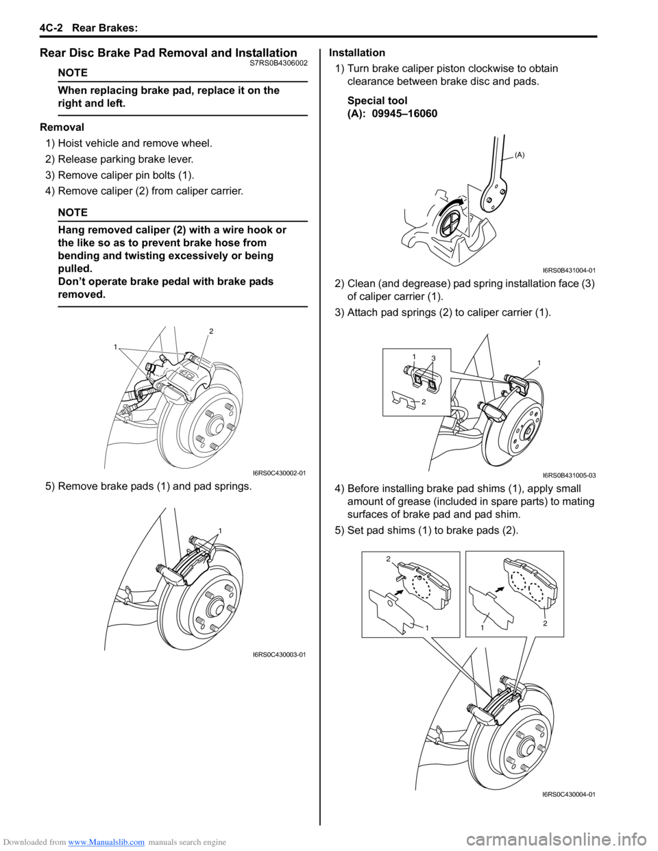
Removal1) Hoist vehicle and remove wheel.
2) Release parking brake lever.
3) Remove caliper pin bolts (1).
4) Remove caliper (2) from caliper carrier.
NOTE
Hang removed caliper (2) with a wire hook or
the like so as to prevent brake hose from
bending and twisting excessively or being
pulled.
Don’t operate brake pedal with brake pads
removed.
5) Remove brake pads (1) and pad springs. Installation
1) Turn brake caliper piston clockwise to obtain clearance between brake disc and pads.
Special tool
(A): 09945–16060
2) Clean (and degrease) pad spring installation face (3) of caliper carrier (1).
3) Attach pad springs (2) to caliper carrier (1).
4) Before installing brake p ad shims (1), apply small
amount of grease (included in spare parts) to mating
surfaces of brake pad and pad shim.
5) Set pad shims (1) to brake pads (2).
1 2
I6RS0C430002-01
1
I6RS0C430003-01
(A)
I6RS0B431004-01
113
2
I6RS0B431005-03
2
1
1 2
I6RS0C430004-01
Page 527 of 1496
Downloaded from www.Manualslib.com manuals search engine Rear Brakes: 4C-3
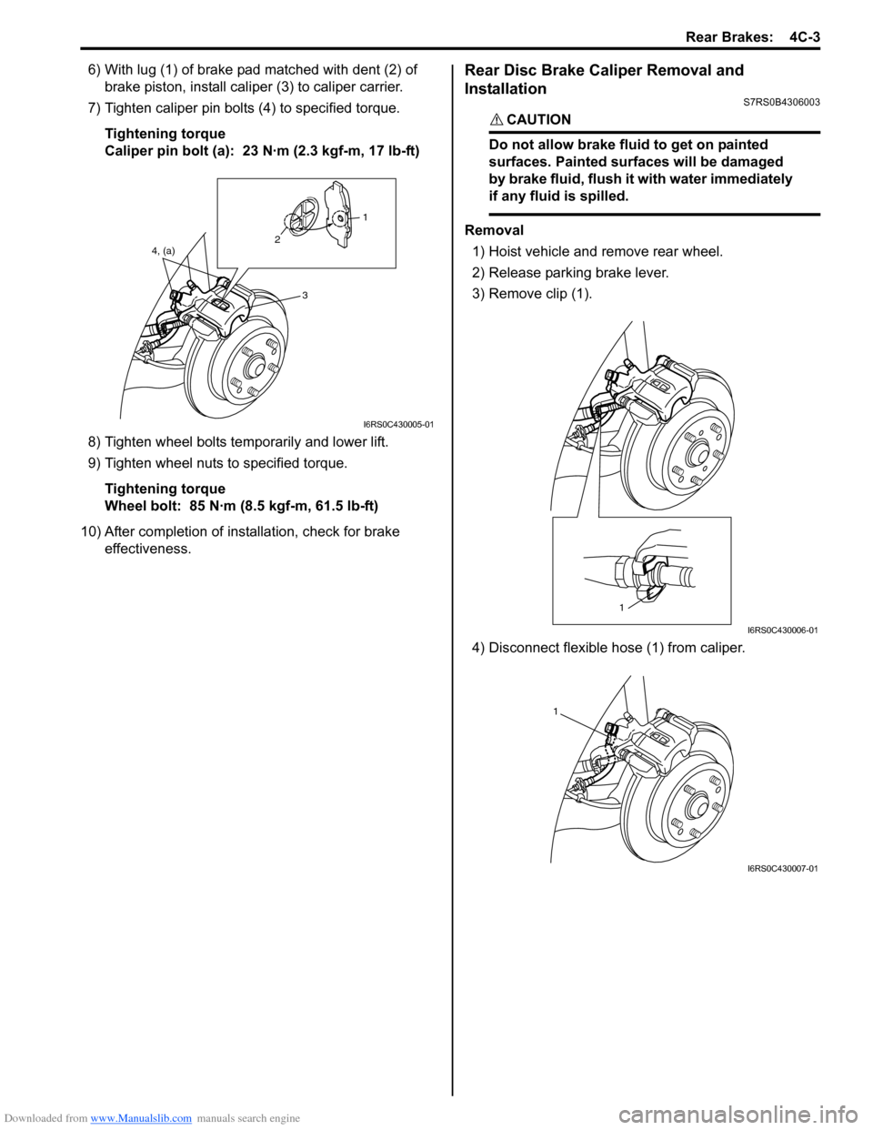
6) With lug (1) of brake pad matched with dent (2) of brake piston, install caliper (3) to caliper carrier.
7) Tighten caliper pin bolts (4) to specified torque.
Tightening torque
Caliper pin bolt (a): 23 N·m (2.3 kgf-m, 17 lb-ft)
8) Tighten wheel bolts temporarily and lower lift.
9) Tighten wheel nuts to specified torque. Tightening torque
Wheel bolt: 85 N·m (8.5 kgf-m, 61.5 lb-ft)
10) After completion of installation, check for brake effectiveness.Rear Disc Brake Caliper Removal and
Installation
S7RS0B4306003
CAUTION!
Do not allow brake fluid to get on painted
surfaces. Painted surfaces will be damaged
by brake fluid, flush it with water immediately
if any fluid is spilled.
Removal
1) Hoist vehicle and remove rear wheel.
2) Release parking brake lever.
3) Remove clip (1).
4) Disconnect flexible hose (1) from caliper.
4, (a) 21
3
I6RS0C430005-01
1
I6RS0C430006-01
1
I6RS0C430007-01
Page 530 of 1496
Downloaded from www.Manualslib.com manuals search engine 4C-6 Rear Brakes:
Rear Disc Brake Pad InspectionS7RS0B4306004
Check pad lining for wear. When wear exceeds limit,
replace with new one.
CAUTION!
Never polish pad lining with sandpaper. If
lining is polished with sandpaper, hard
particles of sandpaper will be deposited in
lining and may damage disc. When pad lining
requires correction, replace it with a new one.
Rear brake pad thickness (lining thickness)
Standard: 9.0 mm (0.354 in.)
Limit: 1.0 mm (0.039 in.)
NOTE
When pads are removed, visually inspect
caliper for brake fluid leak. Correct leaky
point, if any.
Rear Disc Brake Caliper Disassembly and
Assembly
S7RS0B4306005
Disassembly
CAUTION!
Clean around caliper with brake fluid before
disassembly.
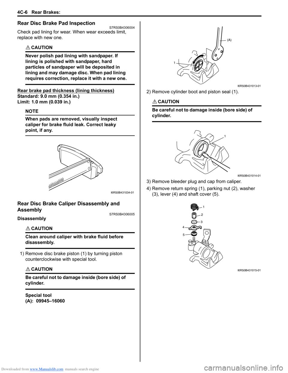
1) Remove disc brake piston (1) by turning piston counterclockwise with special tool.
CAUTION!
Be careful not to damage inside (bore side) of
cylinder.
Special tool
(A): 09945–16060 2) Remove cylinder boot and piston seal (1).
CAUTION!
Be careful not to damage inside (bore side) of
cylinder.
3) Remove bleeder plug and cap from caliper.
4) Remove return spring (1), parking nut (2), washer
(3), lever (4) and shaft cover (5).
I6RS0B431034-01
(A)
1
I6RS0B431013-01
1
I6RS0B431014-01
1
2
3
4
5
I6RS0B431015-01
Page 532 of 1496
Downloaded from www.Manualslib.com manuals search engine 4C-8 Rear Brakes:
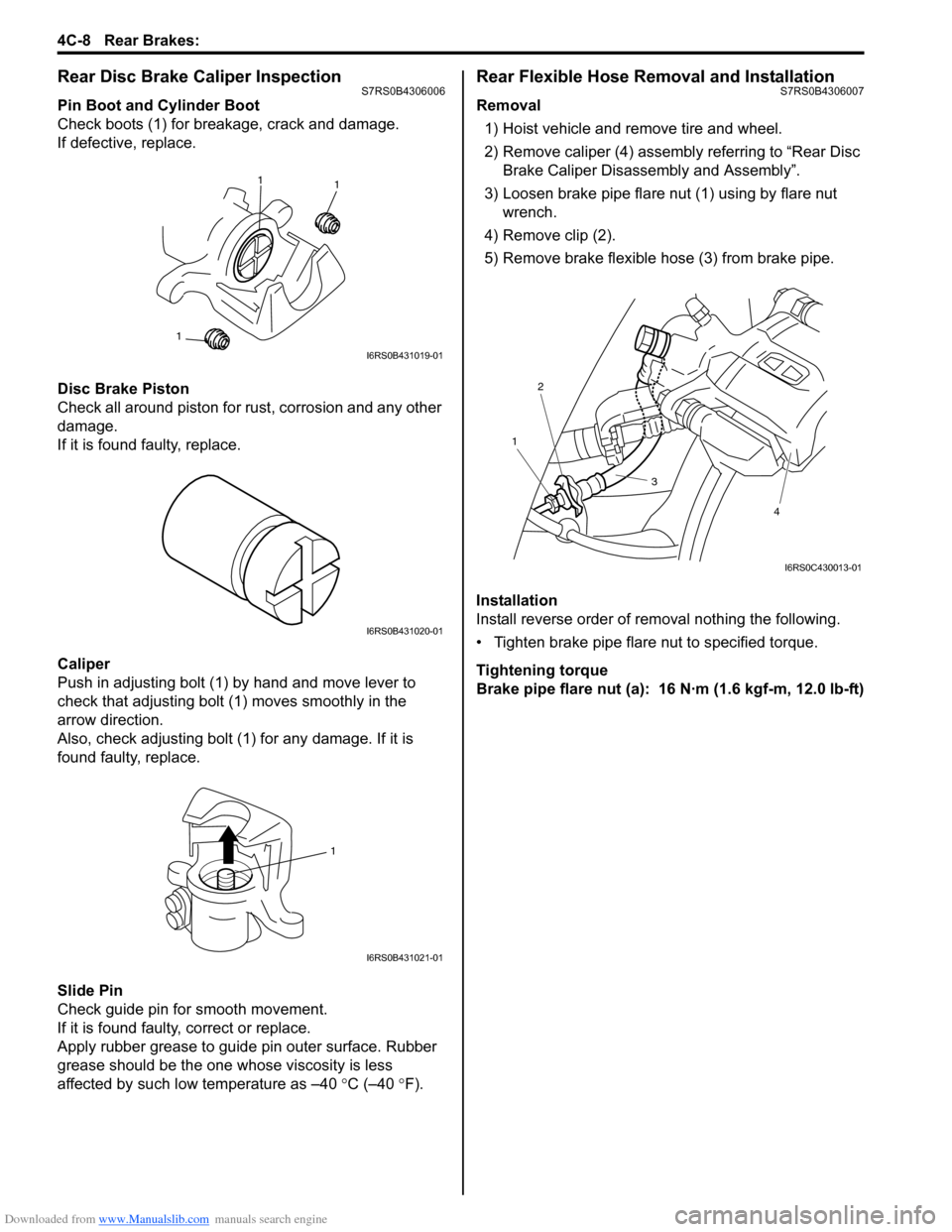
Rear Disc Brake Caliper InspectionS7RS0B4306006
Pin Boot and Cylinder Boot
Check boots (1) for breakage, crack and damage.
If defective, replace.
Disc Brake Piston
Check all around piston for rust, corrosion and any other
damage.
If it is found faulty, replace.
Caliper
Push in adjusting bolt (1) by hand and move lever to
check that adjusting bolt (1) moves smoothly in the
arrow direction.
Also, check adjusting bolt (1) for any damage. If it is
found faulty, replace.
Slide Pin
Check guide pin for smooth movement.
If it is found faulty, correct or replace.
Apply rubber grease to guide pin outer surface. Rubber
grease should be the one whose viscosity is less
affected by such low temperature as –40 °C (–40 ° F).
Rear Flexible Hose Removal and InstallationS7RS0B4306007
Removal
1) Hoist vehicle and remove tire and wheel.
2) Remove caliper (4) assembly referring to “Rear Disc Brake Caliper Disassembly and Assembly”.
3) Loosen brake pipe flare nut (1) using by flare nut wrench.
4) Remove clip (2).
5) Remove brake flexible hose (3) from brake pipe.
Installation
Install reverse order of removal nothing the following.
• Tighten brake pipe flare nut to specified torque.
Tightening torque
Brake pipe flare nut (a): 16 N·m (1.6 kgf-m, 12.0 lb-ft)
1 1
1
I6RS0B431019-01
I6RS0B431020-01
1
I6RS0B431021-01
1
2
3
4
I6RS0C430013-01
Page 533 of 1496
Downloaded from www.Manualslib.com manuals search engine Rear Brakes: 4C-9
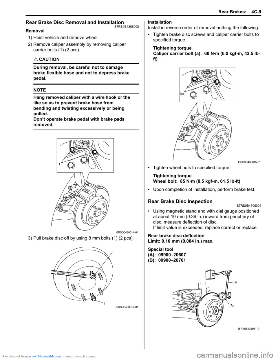
Rear Brake Disc Removal and InstallationS7RS0B4306008
Removal1) Hoist vehicle and remove wheel.
2) Remove caliper assembly by removing caliper
carrier bolts (1) (2 pcs).
CAUTION!
During removal, be ca reful not to damage
brake flexible hose and not to depress brake
pedal.
NOTE
Hang removed caliper with a wire hook or the
like so as to prevent brake hose from
bending and twisting excessively or being
pulled.
Don’t operate brake pedal with brake pads
removed.
3) Pull brake disc off by using 8 mm bolts (1) (2 pcs). Installation
Install in reverse order of removal nothing the following.
• Tighten brake disc screws and caliper carrier bolts to
specified torque.
Tightening torque
Caliper carrier bolt (a): 60 N·m (6.0 kgf-m, 43.5 lb-
ft)
• Tighten wheel nuts to specified torque. Tightening torque
Wheel bolt: 85 N·m (8.5 kgf-m, 61.5 lb-ft)
• Upon completion of installation, perform brake test.
Rear Brake Disc InspectionS7RS0B4306009
• Using magnetic stand and with dial gauge positioned at about 10 mm (0.39 in.) inward from periphery of
disc, measure deflection of disc.
If limit value is exceeded, replace correct or replace.
Rear brake disc deflection
Limit: 0.10 mm (0.004 in.) max.
Special tool
(A): 09900–20607
(B): 09900–20701
1
I6RS0C430014-01
1 1I6RS0C430017-01
(a)
I6RS0C430015-01
(B)
(A)
I6RS0B431031-01
Page 803 of 1496
Downloaded from www.Manualslib.com manuals search engine Automatic Transmission/Transaxle: 5A-159
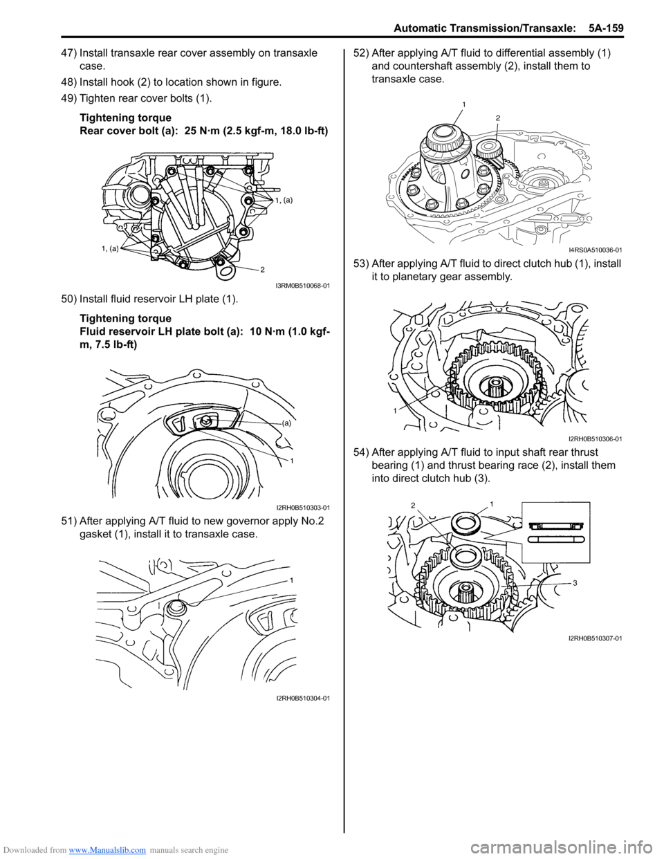
47) Install transaxle rear cover assembly on transaxle case.
48) Install hook (2) to location shown in figure.
49) Tighten rear cover bolts (1).
Tightening torque
Rear cover bolt (a): 25 N·m (2.5 kgf-m, 18.0 lb-ft)
50) Install fluid reservoir LH plate (1). Tightening torque
Fluid reservoir LH plate bolt (a): 10 N·m (1.0 kgf-
m, 7.5 lb-ft)
51) After applying A/T fluid to new governor apply No.2 gasket (1), install it to transaxle case. 52) After applying A/T fluid to differential assembly (1)
and countershaft assembly (2), install them to
transaxle case.
53) After applying A/T fluid to di rect clutch hub (1), install
it to planetary gear assembly.
54) After applying A/T fluid to input shaft rear thrust
bearing (1) and thrust bearing race (2), install them
into direct clutch hub (3).
I3RM0B510068-01
I2RH0B510303-01
I2RH0B510304-01
1
2
I4RS0A510036-01
I2RH0B510306-01
I2RH0B510307-01
Page 854 of 1496
Downloaded from www.Manualslib.com manuals search engine 5C-2 Clutch:
Diagnostic Information and Procedures
Clutch System Symptom DiagnosisS7RS0B5304001
Repair Instructions
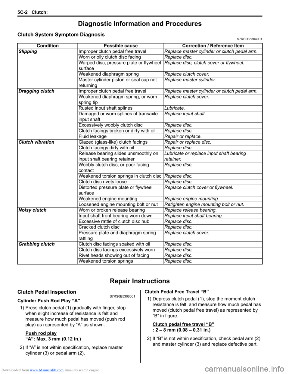
Clutch Pedal InspectionS7RS0B5306001
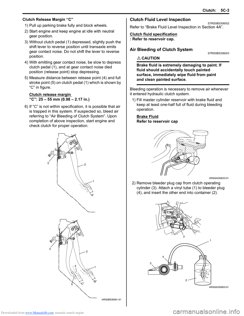
Cylinder Push Rod Play “A”1) Press clutch pedal (1) gradually with finger, stop when slight increase of resistance is felt and
measure how much pedal has moved (push rod
play) as represented by “A” as shown.
Push rod play
“A”: Max. 3 mm (0.12 in.)
2) If “A” is not within specification, replace master cylinder (3) or pedal arm (2). Clutch Pedal Free Travel “B”
1) Depress clutch pedal (1), stop the moment clutch resistance is felt, and measure how much pedal has
moved (clutch pedal free travel) as represented by
“B” in figure.
Clutch pedal free travel
“B”
: 2 – 8 mm (0.08 – 0.31 in.)
2) If “B” is not within specification, check pedal arm (2) and master cylinder (3) and replace defective part.
Condition Possible cause Correction / Reference Item
Slipping Improper clutch pedal free travel Replace master cylinder or clutch pedal arm.
Worn or oily clutch disc facing Replace disc.
Warped disc, pressure plate or flywheel
surface Replace disc, clutch cover or flywheel.
Weakened diaphragm spring Replace clutch cover.
Master cylinder piston or seal cup not
returning Replace master cylinder.
Dragging clutch Improper clutch pedal free travel Replace master cylinder or clutch pedal arm.
Weakened diaphragm spring, or worn
spring tip Replace clutch cover.
Rusted input shaft splines Lubricate.
Damaged or worn splines of transaxle
input shaft Replace input shaft.
Excessively wobbly clutch disc Replace disc.
Clutch facings broken or dirty with oil Replace disc.
Fluid leakage Repair or replace.
Clutch vibration Glazed (glass-like) clutch facings Repair or replace disc.
Clutch facings dirty with oil Replace disc.
Release bearing slides unsmoothly on
input shaft bearing retainer Lubricate or replace input shaft bearing
retainer.
Wobbly clutch disc, or poor facing
contact Replace disc.
Weakened torsion springs in clutch disc Replace disc.
Clutch disc rivets loose Replace disc.
Distorted pressure plate or flywheel
surface Replace clutch cover or flywheel.
Weakened engine mounting Replace engine mounting.
Loosened engine mounting bolt or nut Retighten engine mounting bolt or nut.
Noisy clutch Worn or broken release bearing Replace release bearing.
Input shaft front bearing worn down Replace input shaft bearing.
Excessive rattle of clutch disc hub Replace disc.
Cracked clutch disc Replace disc.
Pressure plate and diaphragm spring
rattling Replace clutch cover.
Grabbing clutch Clutch disc facings soaked with oil Replace disc.
Clutch disc facings excessively worn Replace disc.
Rivet heads showing out of facing Replace disc.
Weakened torsion springs Replace disc.
Page 855 of 1496
Downloaded from www.Manualslib.com manuals search engine Clutch: 5C-3
Clutch Release Margin “C”1) Pull up parking brake fully and block wheels.
2) Start engine and keep engine at idle with neutral gear position.
3) Without clutch pedal (1) dep ressed, slightly push the
shift lever to re verse position until transaxle emits
gear contact noise. Do not shift the lever to reverse
position.
4) With emitting gear contact noise, be slow to depress clutch pedal (1), and at gear contact noise died
position (release point) stop depressing.
5) Measure distance between release point (4) and full stroke point (5) on clutch pedal (1) which is shown by
“C” in figure.
Clutch release margin
“C”: 25 – 55 mm (0.98 – 2.17 in.)
6) If “C” is not within specificat ion, it is possible that air
is trapped in this system. If suspected so, bleed air
referring to “Air Bleeding of Clutch System”. Upon
completion of above inspection, start engine and
check clutch for proper operation.
Clutch Fluid Level InspectionS7RS0B5306002
Refer to “Brake Fluid Level Inspection in Section 4A”.
Clutch fluid specification
: Refer to reservoir cap.
Air Bleeding of Clutch SystemS7RS0B5306003
CAUTION!
Brake fluid is extremely damaging to paint. If
fluid should accidentally touch painted
surface, immediately wipe fluid from paint
and clean painted surface.
Bleeding operation is necessary to remove air whenever
it entered hydraulic clutch system.
1) Fill master cylinder reservoir with brake fluid and keep at least one-half full of fluid during bleeding
operation.
Brake Fluid
Refer to reservoir cap
2) Remove bleeder plug cap from clutch operating cylinder (3). Attach a vinyl tube (1) to bleeder plug
(4), and insert the other end into container (2).
2
1
“A”
3
2
1
3
“B”
“C”
4
5
I4RS0B530001-01
I4RS0A530023-01
3 4 1
2
3
I4RS0A530003-01
Page 856 of 1496
Downloaded from www.Manualslib.com manuals search engine 5C-4 Clutch:
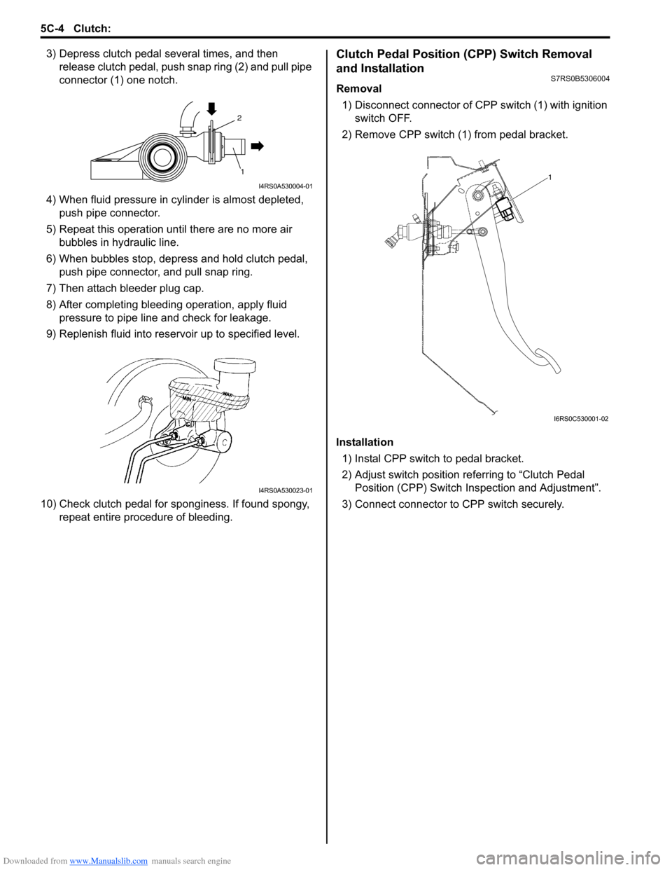
3) Depress clutch pedal several times, and then release clutch pedal, push snap ring (2) and pull pipe
connector (1) one notch.
4) When fluid pressure in cylinder is almost depleted, push pipe connector.
5) Repeat this operation until there are no more air bubbles in hydraulic line.
6) When bubbles stop, depress and hold clutch pedal, push pipe connector, and pull snap ring.
7) Then attach bleeder plug cap.
8) After completing bleeding operation, apply fluid pressure to pipe line and check for leakage.
9) Replenish fluid into reserv oir up to specified level.
10) Check clutch pedal for sponginess. If found spongy, repeat entire procedure of bleeding.Clutch Pedal Position (CPP) Switch Removal
and Installation
S7RS0B5306004
Removal
1) Disconnect connector of C PP switch (1) with ignition
switch OFF.
2) Remove CPP switch (1 ) from pedal bracket.
Installation 1) Instal CPP switch to pedal bracket.
2) Adjust switch position re ferring to “Clutch Pedal
Position (CPP) Switch Inspection and Adjustment”.
3) Connect connector to CPP switch securely.
2
1
I4RS0A530004-01
I4RS0A530023-01
1
I6RS0C530001-02