oil level SUZUKI SWIFT 2008 2.G Service Owner's Manual
[x] Cancel search | Manufacturer: SUZUKI, Model Year: 2008, Model line: SWIFT, Model: SUZUKI SWIFT 2008 2.GPages: 1496, PDF Size: 34.44 MB
Page 416 of 1496
Downloaded from www.Manualslib.com manuals search engine 1J-6 Charging System:
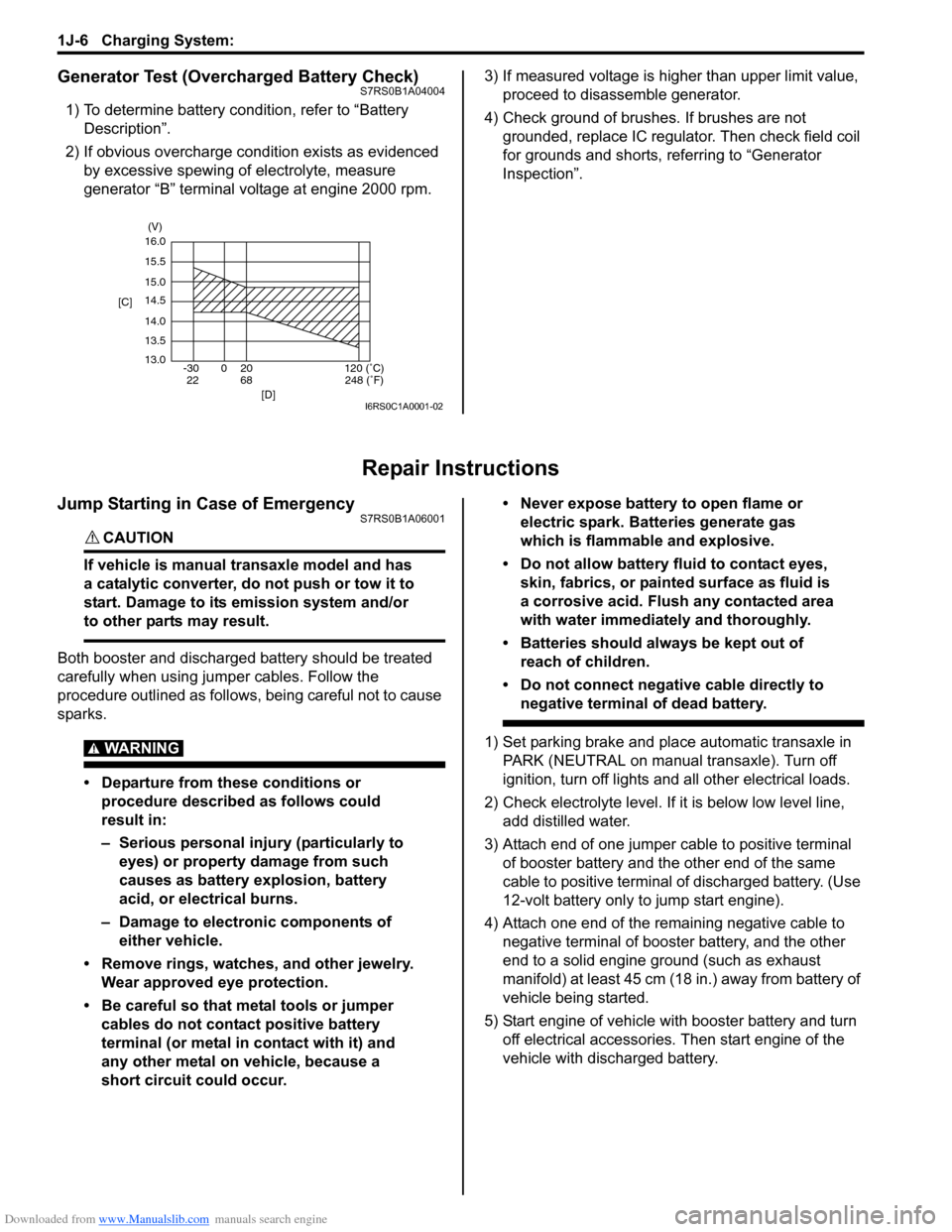
Generator Test (Overcharged Battery Check)S7RS0B1A04004
1) To determine battery condition, refer to “Battery Description”.
2) If obvious overcharge condition exists as evidenced by excessive spewing of electrolyte, measure
generator “B” terminal voltage at engine 2000 rpm. 3) If measured voltage is higher than upper limit value,
proceed to disassemble generator.
4) Check ground of brushes. If brushes are not grounded, replace IC regulator. Then check field coil
for grounds and shorts, referring to “Generator
Inspection”.
Repair Instructions
Jump Starting in Case of EmergencyS7RS0B1A06001
CAUTION!
If vehicle is manual transaxle model and has
a catalytic converter, do not push or tow it to
start. Damage to its emission system and/or
to other parts may result.
Both booster and discharged battery should be treated
carefully when using ju mper cables. Follow the
procedure outlined as follows, being careful not to cause
sparks.
WARNING!
• Departure from these conditions or procedure described as follows could
result in:
– Serious personal injury (particularly to eyes) or property damage from such
causes as battery explosion, battery
acid, or electrical burns.
– Damage to electronic components of either vehicle.
• Remove rings, watches, and other jewelry. Wear approved eye protection.
• Be careful so that metal tools or jumper cables do not contact positive battery
terminal (or metal in contact with it) and
any other metal on vehicle, because a
short circuit could occur. • Never expose battery to open flame or
electric spark. Batteries generate gas
which is flammable and explosive.
• Do not allow battery fluid to contact eyes, skin, fabrics, or painted surface as fluid is
a corrosive acid. Flush any contacted area
with water immediately and thoroughly.
• Batteries should always be kept out of reach of children.
• Do not connect negative cable directly to negative terminal of dead battery.
1) Set parking brake and place automatic transaxle in PARK (NEUTRAL on manual transaxle). Turn off
ignition, turn off lights and all other electrical loads.
2) Check electrolyte level. If it is below low level line, add distilled water.
3) Attach end of one jumper cable to positive terminal of booster battery and the other end of the same
cable to positive terminal of discharged battery. (Use
12-volt battery only to jump start engine).
4) Attach one end of the remaining negative cable to negative terminal of booster battery, and the other
end to a solid engine ground (such as exhaust
manifold) at least 45 cm (18 in.) away from battery of
vehicle being started.
5) Start engine of vehicle with booster battery and turn off electrical accessories. Then start engine of the
vehicle with discharged battery.
16.0
15.5
15.0
14.5
14.0
13.5
13.0 -30 0 20
[C]
[D]
68
22120 (˚C)
248 (˚F)
(V)
I6RS0C1A0001-02
Page 502 of 1496
Downloaded from www.Manualslib.com manuals search engine 4A-4 Brake Control System and Diagnosis:
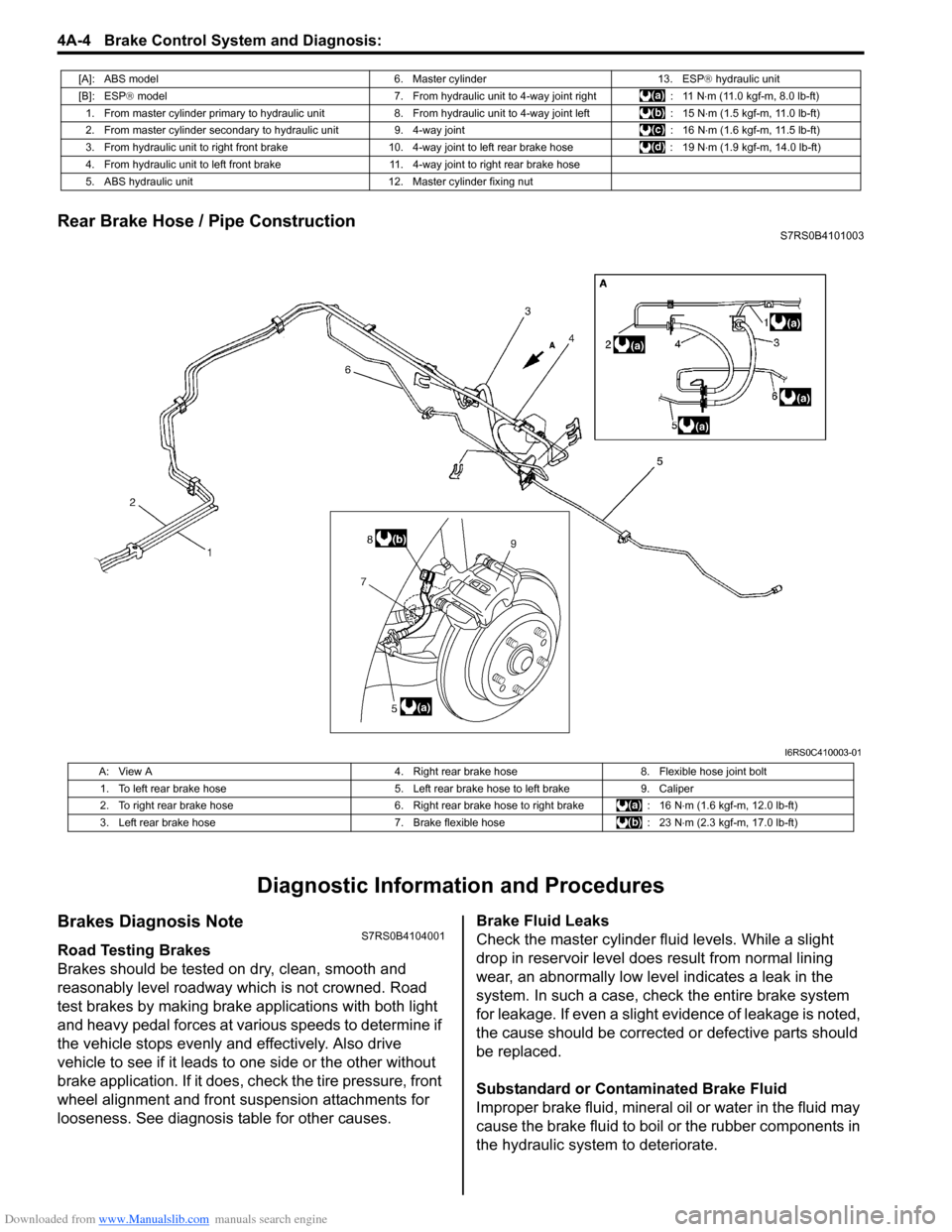
Rear Brake Hose / Pipe ConstructionS7RS0B4101003
Diagnostic Information and Procedures
Brakes Diagnosis NoteS7RS0B4104001
Road Testing Brakes
Brakes should be tested on dry, clean, smooth and
reasonably level roadway which is not crowned. Road
test brakes by making brake applications with both light
and heavy pedal forces at vari ous speeds to determine if
the vehicle stops evenly and effectively. Also drive
vehicle to see if it leads to one side or the other without
brake application. If it does, check the tire pressure, front
wheel alignment and front suspension attachments for
looseness. See diagnosis table for other causes. Brake Fluid Leaks
Check the master cylinder fl
uid levels. While a slight
drop in reservoir level does result from normal lining
wear, an abnormally low leve l indicates a leak in the
system. In such a case, chec k the entire brake system
for leakage. If even a slight ev idence of leakage is noted,
the cause should be corrected or defective parts should
be replaced.
Substandard or Contaminated Brake Fluid
Improper brake fluid, mineral oil or water in the fluid may
cause the brake fluid to boil or the rubber components in
the hydraulic system to deteriorate.
[A]: ABS model 6. Master cylinder13. ESP® hydraulic unit
[B]: ESP ® model 7. From hydraulic unit to 4-way joint right : 11 N⋅m (11.0 kgf-m, 8.0 lb-ft)
1. From master cylinder primary to hydraulic unit 8. From hydraulic unit to 4-way joint left: 15 N⋅m (1.5 kgf-m, 11.0 lb-ft)
2. From master cylinder secondary to hydraulic unit 9. 4-way joint: 16 N⋅m (1.6 kgf-m, 11.5 lb-ft)
3. From hydraulic unit to right front brake 10.4-way joint to left rear brake hose : 19 N⋅m (1.9 kgf-m, 14.0 lb-ft)
4. From hydraulic unit to left front brake 11. 4-way joint to right rear brake hose
5. ABS hydraulic unit 12. Master cylinder fixing nut
I6RS0C410003-01
A: View A4. Right rear brake hose8. Flexible hose joint bolt
1. To left rear brake hose 5. Left rear brake hose to left brake9. Caliper
2. To right rear brake hose 6. Right rear brake hose to right brake: 16 N⋅m (1.6 kgf-m, 12.0 lb-ft)
3. Left rear brake hose 7. Brake flexible hose: 23 N⋅m (2.3 kgf-m, 17.0 lb-ft)
Page 506 of 1496
Downloaded from www.Manualslib.com manuals search engine 4A-8 Brake Control System and Diagnosis:
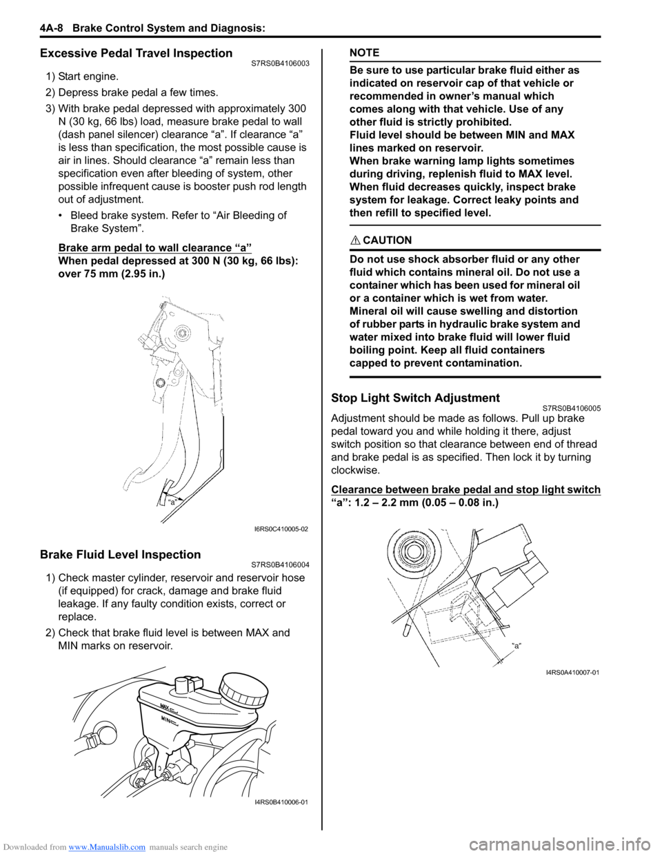
Excessive Pedal Travel InspectionS7RS0B4106003
1) Start engine.
2) Depress brake pedal a few times.
3) With brake pedal depressed with approximately 300 N (30 kg, 66 lbs) load, measure brake pedal to wall
(dash panel silencer) clearance “a”. If clearance “a”
is less than specification, the most possible cause is
air in lines. Should clearance “a” remain less than
specification even after bleeding of system, other
possible infrequent cause is booster push rod length
out of adjustment.
• Bleed brake system. Refer to “Air Bleeding of Brake System”.
Brake arm pedal to wall clearance “a”
When pedal depressed at 300 N (30 kg, 66 lbs):
over 75 mm (2.95 in.)
Brake Fluid Level InspectionS7RS0B4106004
1) Check master cylinder, reservoir and reservoir hose (if equipped) for crack, damage and brake fluid
leakage. If any faulty condition exists, correct or
replace.
2) Check that brake fluid level is between MAX and MIN marks on reservoir.
NOTE
Be sure to use particular brake fluid either as
indicated on reservoir cap of that vehicle or
recommended in owner’s manual which
comes along with that vehicle. Use of any
other fluid is strictly prohibited.
Fluid level should be between MIN and MAX
lines marked on reservoir.
When brake warning lamp lights sometimes
during driving, replenis h fluid to MAX level.
When fluid decreases quickly, inspect brake
system for leakage. Correct leaky points and
then refill to specified level.
CAUTION!
Do not use shock absorber fluid or any other
fluid which contains mineral oil. Do not use a
container which has been used for mineral oil
or a container which is wet from water.
Mineral oil will cause swelling and distortion
of rubber parts in hydraulic brake system and
water mixed into brake fluid will lower fluid
boiling point. Keep all fluid containers
capped to prevent contamination.
Stop Light Switch AdjustmentS7RS0B4106005
Adjustment should be made as follows. Pull up brake
pedal toward you and while holding it there, adjust
switch position so that clea rance between end of thread
and brake pedal is as specified. Then lock it by turning
clockwise.
Clearance between brake pedal and stop light switch
“a”: 1.2 – 2.2 mm (0.05 – 0.08 in.)
I6RS0C410005-02
I4RS0B410006-01
I4RS0A410007-01
Page 642 of 1496

Downloaded from www.Manualslib.com manuals search engine 5-ii Table of Contents
DTC P1878: Torque Converter Clutch Shudder .......................................................... 5A-75
DTC P2762: Torque Converter Clutch (TCC) Pressure Control Sole noid Control Circuit
Range /Performance ....................................... 5A-76
DTC P2763: Torque Converter Clutch Pressure Control Sole noid Control Circuit
High ................................................................. 5A-78
DTC P2764: Torque Converter Clutch Circuit Pressure Control Sole noid Control Circuit
Low ................................................................. 5A-80
Inspection of TCM and Its Circuits .................... 5A-82
TCM Power and Ground Circuit Check ............. 5A-86
Brake Interlock System Inspection .................... 5A-87
Repair Instructions ........... .................................5A-88
Learning Control Initializat ion ............................ 5A-88
A/T Fluid Level Check ....................................... 5A-89
A/T Fluid Change .............................................. 5A-90
Select Lever Components ... .............................. 5A-90
Select Lever Assembly Removal and Installation ....................................................... 5A-90
Select Lever Knob Installa tion........................... 5A-90
Select Lever Inspection .... ................................. 5A-91
“3” Position Switch Inspec tion ........................... 5A-91
Shift Lock Solenoid Inspec tion .......................... 5A-91
Shift Lock Solenoid Replacement ..................... 5A-91
Select Cable Components ................................ 5A-92
Select Cable Removal and Installation ............. 5A-92
Select Cable Adjustment ................................... 5A-93
Key Interlock Cable Removal and Installation... 5A-93
Transmission Range Sensor (Shift Switch) Inspection and Adjustment .............................. 5A-95
Output Shaft Speed Sensor Removal and Installation ....................................................... 5A-96
Output Shaft Speed Sensor Inspection ............. 5A-96
Input Shaft Speed Sensor Removal and Installation ....................................................... 5A-96
Input Shaft Speed Sensor Inspection................ 5A-97
Transmission Fluid Temperature Sensor Removal and Installation ................................. 5A-97
Transmission Fluid Temperature Sensor Inspection ........................................................ 5A-98
Solenoid Valves (Shift Solenoid Valves and Timing Solenoid Valve) Removal and
Installation ....................................................... 5A-98
Solenoid Valves (Shift Solenoid Valves, and Timing Solenoid Valve) Inspection .................. 5A-99
Pressure Control Soleno id Valves (Pressure
Control Solenoid and TCC Pressure Control
Solenoid) Removal and Inst allation .............. 5A-101
Pressure Control Solenoid Valve Inspection ... 5A-101
Transmission Control Module (TCM) Removal and Installation ............................... 5A-102
A/T Relay Inspection ....................................... 5A-103
Differential Side Oil Seal Replacement ........... 5A-103
A/T Fluid Cooler Hoses Replacement ............. 5A-104
Automatic Transaxle Unit Components........... 5A-105
Automatic Transaxle Unit Dismounting and Remounting ................................................... 5A-106
Automatic Transaxle Asse mbly Components . 5A-108 Automatic Transaxle Unit
Disassembly........... 5A-110
Oil Pump Assembly Components ................... 5A-121
Oil Pump Assembly Disassembly and Reassembly .................................................. 5A-122
Oil Pump Assembly Inspection ....................... 5A-122
Direct Clutch Assembly Components.............. 5A-124
Direct Clutch Assembly Preliminary Check ..... 5A-124
Direct Clutch Assembly Disassembly and Reassembly .................................................. 5A-125
Direct Clutch Assembly Inspection.................. 5A-127
Forward and Reverse Clutch Assembly Components .................................................. 5A-128
Forward and Reverse Clutch Assembly Preliminary Check ......................................... 5A-129
Forward and Reverse Clutch Assembly Disassembly and Reassembly ...................... 5A-129
Forward and Reverse Clutch Assembly Inspection ...................................................... 5A-133
2nd Brake Piston Assembly Components ....... 5A-134
2nd Brake Piston Assembly Disassembly and Reassembly .................................................. 5A-134
Transaxle Rear Cover (O/D and 2nd Coast Brake Piston) Assembly Components........... 5A-135
Transaxle Rear Cover (O/D and 2nd Coast Brake Piston) Assembly Disassembly and
Reassembly .................................................. 5A-136
Transaxle Rear Cover (O/D and 2nd Coast Brake Piston) Assembly Inspection............... 5A-137
Countershaft Assembly Co mponents.............. 5A-138
Countershaft Assembly Disassembly and Reassembly .................................................. 5A-138
Valve Body Assembly Components ................ 5A-139
Valve Body Assembly Disassembly and Reassembly .................................................. 5A-140
Differential Assembly Components ................. 5A-141
Differential Assembly Disassembly and Reassembly .................................................. 5A-142
Differential Assembly Inspection ..................... 5A-143
Torque Converter Housing Disassembly and Reassembly .................................................. 5A-144
Transaxle Case Disassembly and Reassembly .................................................. 5A-146
Automatic Transaxle Unit Inspection and Adjus
tment .................................................... 5A-147
Automatic Transaxle Unit Assembly ............... 5A-150
Specifications .................. .................................5A-167
Tightening Torque Specifications .................... 5A-167
Special Tools and Equipmen t .........................5A-168
Recommended Service Material ..................... 5A-168
Special Tool .................................................... 5A-168
Manual Transmission/Tr ansaxle ............ 5B-1
General Description .............................................5B-1
Manual Transaxle Construction and Servicing .... 5B-1
Diagnostic Information and Procedures ............5B-3 Manual Transaxle Symptom Diagnosis............... 5B-3
Repair Instructions ............ ..................................5B-3
Manual Transaxle Oil Change............................. 5B-3
Differential Side Oil Seal Replacement ............... 5B-4
Page 662 of 1496

Downloaded from www.Manualslib.com manuals search engine 5A-18 Automatic Transmission/Transaxle:
Visual InspectionS7RS0B5104002
Visually check the following parts and systems.
Malfunction Indicator Lamp (MIL) CheckS7RS0B5104003
Refer to the same item in “Malfunction Indicator Lam p (MIL) Check in Section 1A” for checking procedure.
Transmission Warning Light CheckS7RS0B5104004
1) Turn ignition switch ON.
2) Check that transmission warning light lights for about 2 – 4 sec. and then goes OFF.
If anything faulty is found, advance “Transmission Warn ing Light Circuit Check – Light Does Not Come “ON” at
Ignition Switch ON” or “Transmission Warning Light Circu it Check – Light Remains “ON” at Ignition Switch ON”.
Inspection item Referring
• A/T fluid ----- level, leakage, color “Automatic Transaxle Fluid Level Inspection in Section 0B”
• A/T fluid hoses ----- disconnection, looseness, deterioration “A/T Fluid Cooler Hoses Replacement”
• A/T select cable ----- installation “S elect Cable Removal and Installation”
• Engine oil ----- level, leakage “Engine Oil and Filter Change in Section 0B”
• Engine coolant ----- level, leakage “Engine Coolant Change in Section 0B”
• Engine mountings ----- play, looseness, damage “Engine Assembly Removal and Installation in Section 1D”
• Suspension ----- play, looseness “Suspension, Wheels and Tires Symptom Diagnosis in Section 2A”
• Drive shafts ----- damage “Front Drive Shaft Assembly On-Vehicle Inspection in Section 3A”
• Battery ----- indicator condition, corrosion of terminal “Battery Inspection in Section 1J”
• Connectors of electric wire harness ----- disconnection, friction “Electronic Shift Control System Components
Location”
• Fuses ----- burning
• Parts ----- installation, damage
• Bolts ----- looseness
• Other parts that can be checked visually
Also check the following items at engine start, if possible.
• Transmission warning light (if equipped) ----- Operation “Transmission Warning Light Check”
• Malfunction indicator lamp ----- Operation “Malfunction Indicator Lamp (MIL) Check”
• Charge warning lamp ----- Operation “Generator Symptom Diagnosis in Section 1J”
• Engine oil pressure warning lamp ----- Operation “Oil Pressure Warning Ligh t Symptom Diagnosis in
Section 9C”
• Engine coolant temp. meter ----- Operation “Engine Coolant Temperature (ECT) Meter
Symptom Diagnosis in Section 9C”
• Other parts that can be checked visually
I4RS0A510008-01
Page 671 of 1496
Downloaded from www.Manualslib.com manuals search engine Automatic Transmission/Transaxle: 5A-27
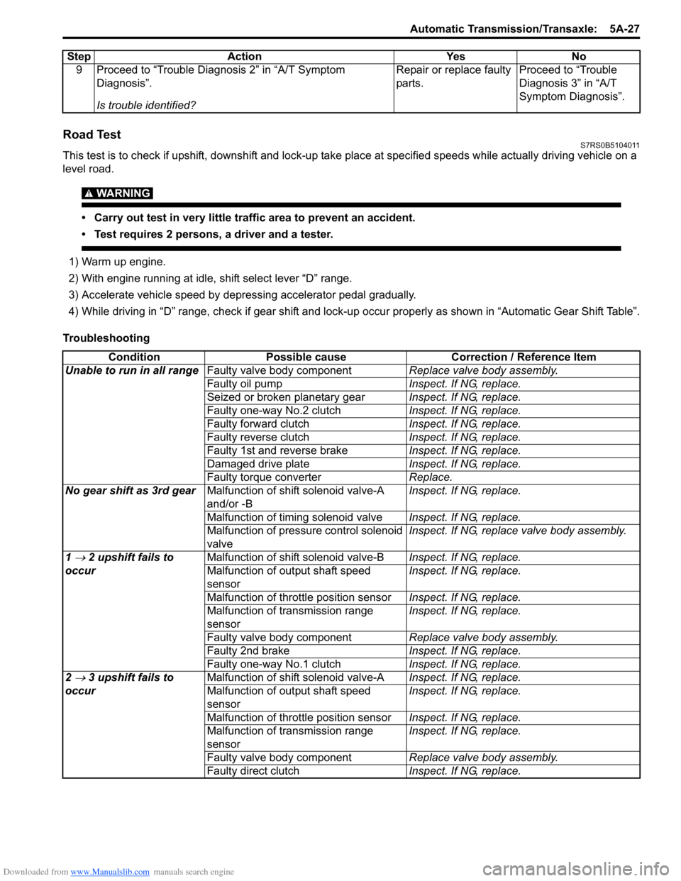
Road TestS7RS0B5104011
This test is to check if upshift, downshift and lock-up take place at specified speeds while actually driving vehicle on a
level road.
WARNING!
• Carry out test in very little traffic area to prevent an accident.
• Test requires 2 persons, a driver and a tester.
1) Warm up engine.
2) With engine running at idle, shift select lever “D” range.
3) Accelerate vehicle speed by depressing accelerator pedal gradually.
4) While driving in “D” range, check if gear shift and lock-up occur properly as shown in “Automatic Gear Shift Table”.
Troubleshooting 9 Proceed to “Trouble Diag
nosis 2” in “A/T Symptom
Diagnosis”.
Is trouble identified? Repair or replace faulty
parts.
Proceed to “Trouble
Diagnosis 3” in “A/T
Symptom Diagnosis”.
Step Action Yes No
Condition
Possible cause Correction / Reference Item
Unable to run in all range Faulty valve body component Replace valve body assembly.
Faulty oil pump Inspect. If NG, replace.
Seized or broken planetary gear Inspect. If NG, replace.
Faulty one-way No.2 clutch Inspect. If NG, replace.
Faulty forward clutch Inspect. If NG, replace.
Faulty reverse clutch Inspect. If NG, replace.
Faulty 1st and reverse brake Inspect. If NG, replace.
Damaged drive plate Inspect. If NG, replace.
Faulty torque converter Replace.
No gear shift as 3rd gear Malfunction of shift solenoid valve-A
and/or -B Inspect. If NG, replace.
Malfunction of timing solenoid valve Inspect. If NG, replace.
Malfunction of pressure control solenoid
valve Inspect. If NG, replace valve body assembly.
1
→ 2 upshift fails to
occur Malfunction of shif
t solenoid valve-B Inspect. If NG, replace.
Malfunction of output shaft speed
sensor Inspect. If NG, replace.
Malfunction of throttle position sensor Inspect. If NG, replace.
Malfunction of transmission range
sensor Inspect. If NG, replace.
Faulty valve body component Replace valve body assembly.
Faulty 2nd brake Inspect. If NG, replace.
Faulty one-way No.1 clutch Inspect. If NG, replace.
2
→ 3 upshift fails to
occur Malfunction of shif
t solenoid valve-A Inspect. If NG, replace.
Malfunction of output shaft speed
sensor Inspect. If NG, replace.
Malfunction of throttle position sensor Inspect. If NG, replace.
Malfunction of transmission range
sensor Inspect. If NG, replace.
Faulty valve body component Replace valve body assembly.
Faulty direct clutch Inspect. If NG, replace.
Page 675 of 1496
Downloaded from www.Manualslib.com manuals search engine Automatic Transmission/Transaxle: 5A-31
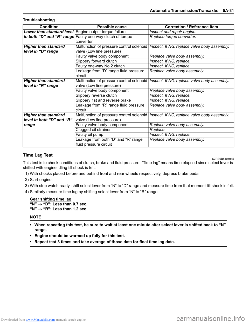
Troubleshooting
Time Lag TestS7RS0B5104015
This test is to check conditions of clutch, brake and fluid pressure. “Time lag” means time elapsed since select lever is
shifted with engine idling till shock is felt.
1) With chocks placed before and behind front and rear wheels respectively, depress brake pedal.
2) Start engine.
3) With stop watch ready, shift select lever from “N” to “D” range an d measure time from that moment till shock is felt.
4) Similarly measure time lag by shifting select lever from “N” to “R” range.
Gear shifting time lag
“N” → “D”: Less than 0.7 sec.
“N” → “R”: Less than 1.2 sec.
NOTE
• When repeating this test, be sure to wait at least one minute after select lever is shifted back to “N”
range.
• Engine should be warmed up fully for this test.
• Repeat test 3 times and take average of those data for final time lag data.
Condition Possible cause Correction / Reference Item
Lower than standard level
in both “D” and “R” range Engine output torque failure
Inspect and repair engine.
Faulty one-way clutch of torque
converter Replace torque converter.
Higher than standard
level in “D” range Malfunction of pressure control solenoid
valve (Low line pressure) Inspect. If NG, replace valve body assembly.
Faulty valve body component Replace valve body assembly.
Slippery forward clutch Inspect. If NG, replace.
Faulty one-way No.2 clutch Inspect. If NG, replace.
Leakage from “D” range fluid pressure
circuit Replace valve body assembly.
Higher than standard
level in “R” range Malfunction of pressure control solenoid
valve (Low line pressure) Inspect. If NG, replace valve body assembly.
Faulty valve body component Replace valve body assembly.
Slippery reverse clutch Inspect. If NG, replace.
Slippery 1st and reverse brake Inspect. If NG, replace.
Leakage from “R” range fluid pressure
circuit Replace valve body assembly.
Higher than standard
level in both “D” and “R”
range Malfunction of pressure control solenoid
valve (Low line pressure)
Inspect. If NG, replace valve body assembly.
Faulty valve body component Replace valve body assembly.
Clogged oil strainer Replace.
Faulty oil pump Inspect. If NG, replace.
Leakage from both “D” and “R” range
fluid pressure circuit Replace valve body assembly.
Page 676 of 1496
Downloaded from www.Manualslib.com manuals search engine 5A-32 Automatic Transmission/Transaxle:
Troubleshooting
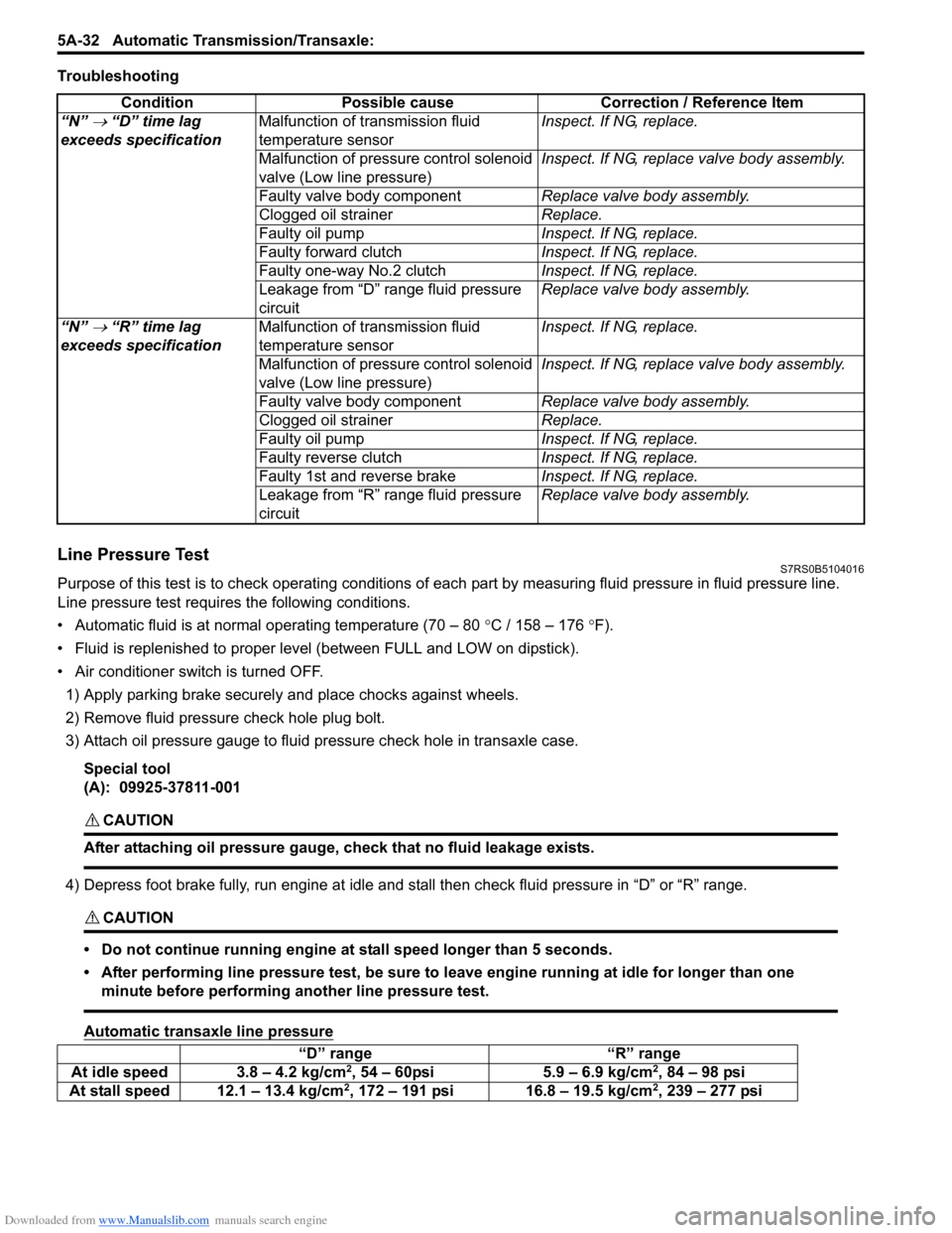
Line Pressure TestS7RS0B5104016
Purpose of this test is to check operat ing conditions of each part by measuring fluid pressure in fluid pressure line.
Line pressure test requires the following conditions.
• Automatic fluid is at normal operating temperature (70 – 80 °C / 158 – 176 °F).
• Fluid is replenished to proper level (between FULL and LOW on dipstick).
• Air conditioner switch is turned OFF.
1) Apply parking brake securely and place chocks against wheels.
2) Remove fluid pressure check hole plug bolt.
3) Attach oil pressure gauge to fluid pr essure check hole in transaxle case.
Special tool
(A): 09925-37811-001
CAUTION!
After attaching oil pressure gauge, check that no fluid leakage exists.
4) Depress foot brake fully, run engine at idle and stall then check fluid pressure in “D” or “R” range.
CAUTION!
• Do not continue running engine at stall speed longer than 5 seconds.
• After performing line pressure test, be sure to leave engine running at idle for longer than one minute before performing another line pressure test.
Automatic transaxle line pressure
Condition Possible cause Correction / Reference Item
“N”
→ “D” time lag
exceeds specification Malfunction of transmission fluid
temperature sensor Inspect. If NG, replace.
Malfunction of pressure control solenoid
valve (Low line pressure) Inspect. If NG, replace valve body assembly.
Faulty valve body component Replace valve body assembly.
Clogged oil strainer Replace.
Faulty oil pump Inspect. If NG, replace.
Faulty forward clutch Inspect. If NG, replace.
Faulty one-way No.2 clutch Inspect. If NG, replace.
Leakage from “D” range fluid pressure
circuit Replace valve body assembly.
“N”
→ “R” time lag
exceeds specification Malfunction of transmission fluid
temperature sensor Inspect. If NG, replace.
Malfunction of pressure control solenoid
valve (Low line pressure) Inspect. If NG, replace valve body assembly.
Faulty valve body component Replace valve body assembly.
Clogged oil strainer Replace.
Faulty oil pump Inspect. If NG, replace.
Faulty reverse clutch Inspect. If NG, replace.
Faulty 1st and reverse brake Inspect. If NG, replace.
Leakage from “R” range fluid pressure
circuit Replace valve body assembly.
“D” range
“R” range
At idle speed 3.8 – 4.2 kg/cm2, 54 – 60psi 5.9 – 6.9 kg/cm2, 84 – 98 psi
At stall speed 12.1 – 13.4 kg/cm2, 172 – 191 psi 16.8 – 19.5 kg/cm2, 239 – 277 psi
Page 677 of 1496
Downloaded from www.Manualslib.com manuals search engine Automatic Transmission/Transaxle: 5A-33
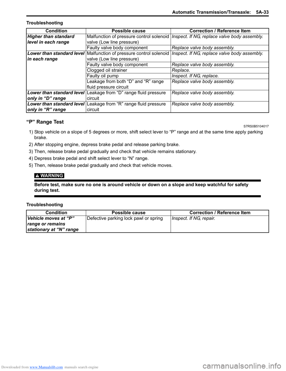
Troubleshooting
“P” Range TestS7RS0B5104017
1) Stop vehicle on a slope of 5 degrees or more, shift select lever to “P” range and at the same time apply parking brake.
2) After stopping engine, depress brake pedal and release parking brake.
3) Then, release brake pedal gradually and check that vehicle remains stationary.
4) Depress brake pedal and shift select lever to “N” range.
5) Then, release brake pedal gradually and check that vehicle moves.
WARNING!
Before test, make sure no one is around vehicle or down on a slope and keep watchful for safety
during test.
Troubleshooting Condition Possible cause Correction / Reference Item
Higher than standard
level in each range Malfunction of pressure control solenoid
valve (Low line pressure) Inspect. If NG, replace valve body assembly.
Faulty valve body component Replace valve body assembly.
Lower than standard level
in each range Malfunction of pressure control solenoid
valve (Low line pressure) Inspect. If NG, replace valve body assembly.
Faulty valve body component Replace valve body assembly.
Clogged oil strainer Replace.
Faulty oil pump Inspect. If NG, replace.
Leakage from both “D” and “R” range
fluid pressure circuit Replace valve body assembly.
Lower than standard level
only in “D” range Leakage from “D” range fluid pressure
circuit Replace valve body assembly.
Lower than standard level
only in “R” range Leakage from “R” range fluid pressure
circuit Replace valve body assembly.
Condition
Possible cause Correction / Reference Item
Vehicle moves at “P”
range or remains
stationary at “N” range Defective parking lock pawl or spring
Inspect. If NG, repair.
Page 685 of 1496
Downloaded from www.Manualslib.com manuals search engine Automatic Transmission/Transaxle: 5A-41
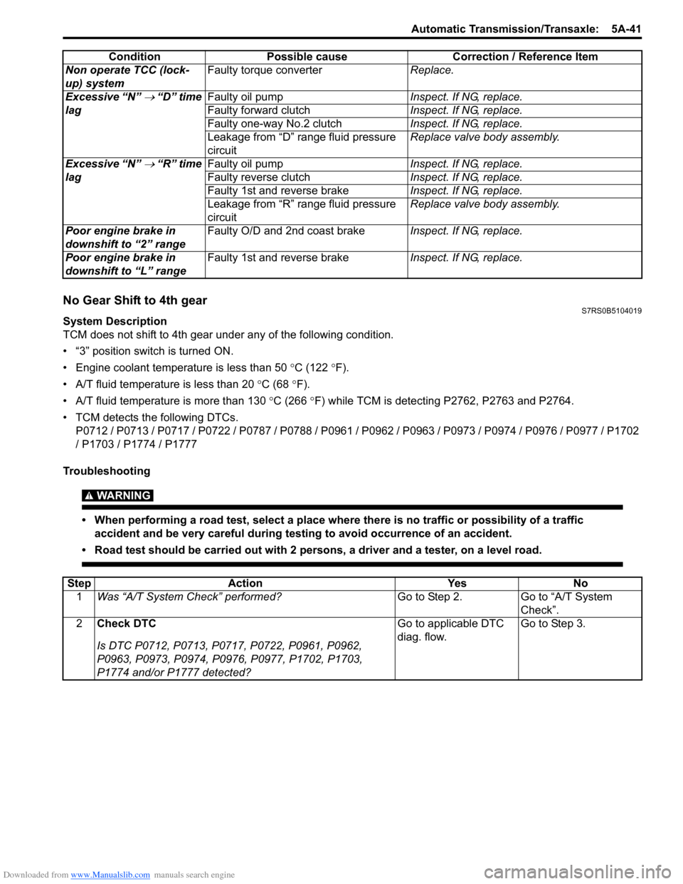
No Gear Shift to 4th gearS7RS0B5104019
System Description
TCM does not shift to 4th gear under any of the following condition.
• “3” position switch is turned ON.
• Engine coolant temperature is less than 50 °C (122 °F).
• A/T fluid temperature is less than 20 °C (68 °F).
• A/T fluid temperature is more than 130 °C (266 °F) while TCM is detecting P2762, P2763 and P2764.
• TCM detects the following DTCs. P0712 / P0713 / P0717 / P0722 / P0787 / P0788 / P0961 / P0962 / P0963 / P0973 / P0974 / P0976 / P0977 / P1702
/ P1703 / P1774 / P1777
Troubleshooting
WARNING!
• When performing a road test, select a place where there is no traffic or possibility of a traffic accident and be very careful during testing to avoid occurrence of an accident.
• Road test should be carried out with 2 persons, a driver and a tester, on a level road.
Non operate TCC (lock-
up) system Faulty torque converter
Replace.
Excessive “N”
→ “D” time
lag Faulty oil pump
Inspect. If NG, replace.
Faulty forward clutch Inspect. If NG, replace.
Faulty one-way No.2 clutch Inspect. If NG, replace.
Leakage from “D” range fluid pressure
circuit Replace valve body assembly.
Excessive “N”
→ “R” time
lag Faulty oil pump
Inspect. If NG, replace.
Faulty reverse clutch Inspect. If NG, replace.
Faulty 1st and reverse brake Inspect. If NG, replace.
Leakage from “R” range fluid pressure
circuit Replace valve body assembly.
Poor engine brake in
downshift to “2” range Faulty O/D and 2nd coast brake
Inspect. If NG, replace.
Poor engine brake in
downshift to “L” range Faulty 1st and reverse brake
Inspect. If NG, replace.
Condition Possible cause Correction / Reference Item
Step
Action YesNo
1 Was “A/T System Check” performed? Go to Step 2.Go to “A/T System
Check”.
2 Check DTC
Is DTC P0712, P0713, P0717, P0722, P0961, P0962,
P0963, P0973, P0974, P0976, P0977, P1702, P1703,
P1774 and/or P1777 detected? Go to applicable DTC
diag. flow.
Go to Step 3.