oil level SUZUKI SWIFT 2008 2.G Service Owner's Guide
[x] Cancel search | Manufacturer: SUZUKI, Model Year: 2008, Model line: SWIFT, Model: SUZUKI SWIFT 2008 2.GPages: 1496, PDF Size: 34.44 MB
Page 741 of 1496
Downloaded from www.Manualslib.com manuals search engine Automatic Transmission/Transaxle: 5A-97
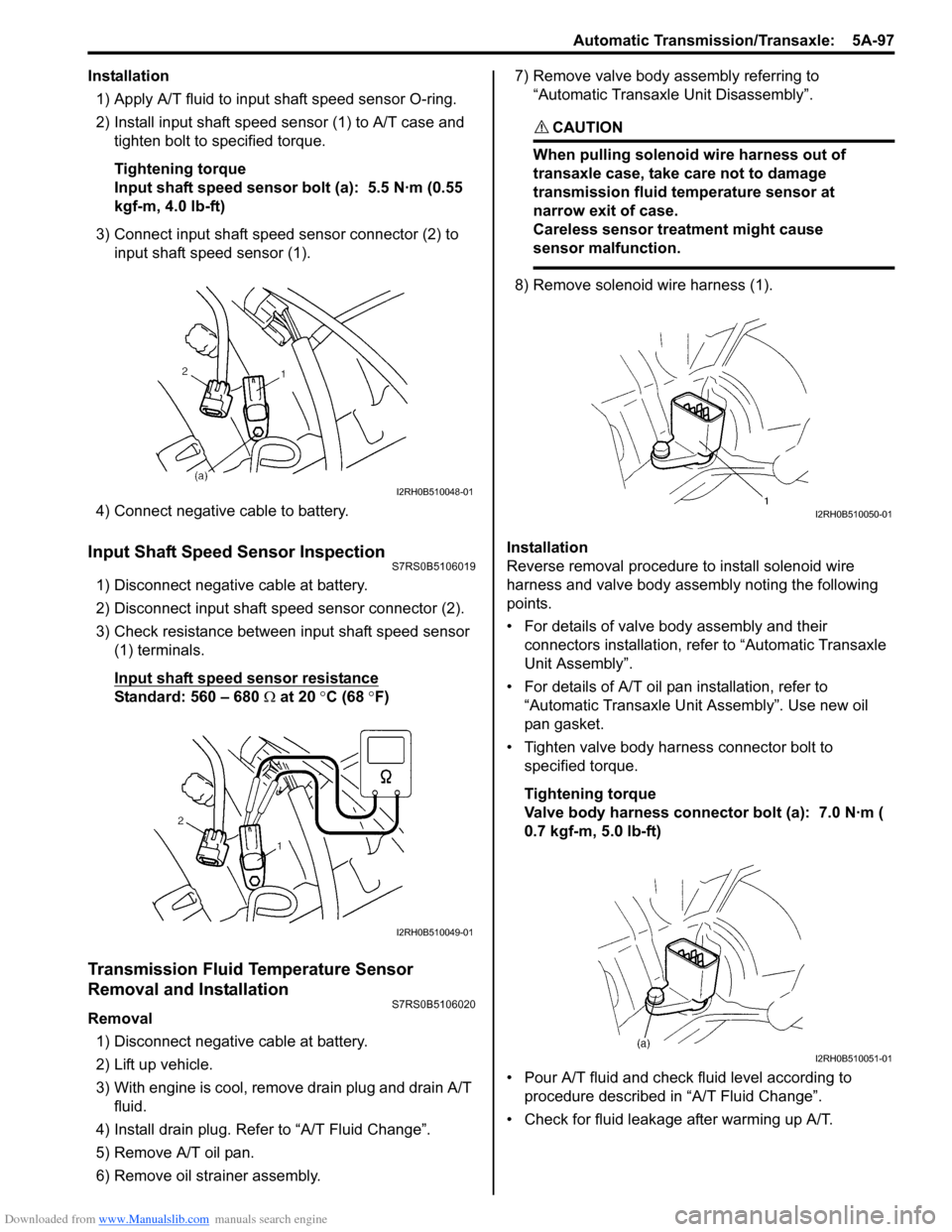
Installation1) Apply A/T fluid to input shaft speed sensor O-ring.
2) Install input shaft speed se nsor (1) to A/T case and
tighten bolt to specified torque.
Tightening torque
Input shaft speed sensor bolt (a): 5.5 N·m (0.55
kgf-m, 4.0 lb-ft)
3) Connect input shaft speed sensor connector (2) to input shaft speed sensor (1).
4) Connect negative cable to battery.
Input Shaft Speed Sensor InspectionS7RS0B5106019
1) Disconnect negative cable at battery.
2) Disconnect input shaft speed sensor connector (2).
3) Check resistance between input shaft speed sensor (1) terminals.
Input shaft speed sensor resistance
Standard: 560 – 680 Ω at 20 °C (68 °F)
Transmission Fluid Temperature Sensor
Removal and Installation
S7RS0B5106020
Removal
1) Disconnect negative cable at battery.
2) Lift up vehicle.
3) With engine is cool, remove drain plug and drain A/T fluid.
4) Install drain plug. Refer to “A/T Fluid Change”.
5) Remove A/T oil pan.
6) Remove oil stra iner assembly. 7) Remove valve body assembly referring to
“Automatic Transaxl e Unit Disassembly”.
CAUTION!
When pulling solenoid wire harness out of
transaxle case, take care not to damage
transmission fluid temperature sensor at
narrow exit of case.
Careless sensor treatment might cause
sensor malfunction.
8) Remove solenoid wire harness (1).
Installation
Reverse removal procedure to install solenoid wire
harness and valve body assembly noting the following
points.
• For details of valve body assembly and their connectors installation, refer to “Automatic Transaxle
Unit Assembly”.
• For details of A/T oil pa n installation, refer to
“Automatic Transaxle Unit Assembly”. Use new oil
pan gasket.
• Tighten valve body harness connector bolt to specified torque.
Tightening torque
Valve body harness connector bolt (a): 7.0 N·m (
0.7 kgf-m, 5.0 lb-ft)
• Pour A/T fluid and check fluid level according to procedure described in “A/T Fluid Change”.
• Check for fluid leakage after warming up A/T.
I2RH0B510048-01
I2RH0B510049-01
I2RH0B510050-01
I2RH0B510051-01
Page 745 of 1496
Downloaded from www.Manualslib.com manuals search engine Automatic Transmission/Transaxle: 5A-101
Pressure Control Solenoid Valves (Pressure
Control Solenoid and TCC Pressure Control
Solenoid) Removal and Installation
S7RS0B5106024
Removal1) Disconnect negative cable at battery.
2) Lift up vehicle.
3) Remove drain plug and drain A/T fluid.
4) Install drain plug.
Tightening torque
A/T fluid drain plug: 17 N·m (1.7 kgf-m, 12.5 lb-ft)
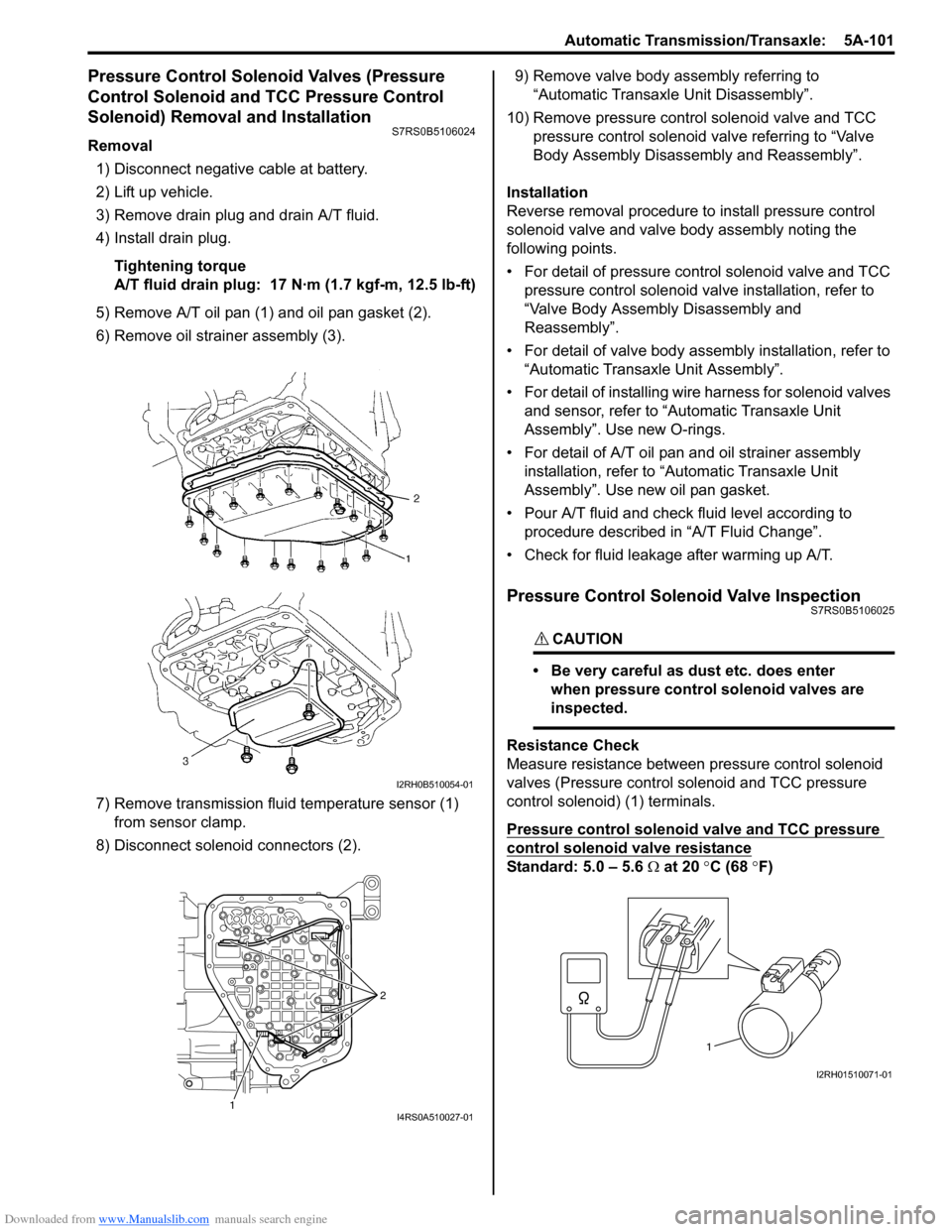
5) Remove A/T oil pan (1) and oil pan gasket (2).
6) Remove oil strain er assembly (3).
7) Remove transmission fluid temperature sensor (1) from sensor clamp.
8) Disconnect solenoid connectors (2). 9) Remove valve body assembly referring to
“Automatic Transaxl e Unit Disassembly”.
10) Remove pressure control solenoid valve and TCC pressure control solenoid valve referring to “Valve
Body Assembly Disassembly and Reassembly”.
Installation
Reverse removal procedure to install pressure control
solenoid valve and valve body assembly noting the
following points.
• For detail of pressure control solenoid valve and TCC pressure control solenoid va lve installation, refer to
“Valve Body Assembly Disassembly and
Reassembly”.
• For detail of valve body asse mbly installation, refer to
“Automatic Transaxle Unit Assembly”.
• For detail of installing wire harness for solenoid valves and sensor, refer to “Automatic Transaxle Unit
Assembly”. Use new O-rings.
• For detail of A/T oil pan and oil strainer assembly
installation, refer to “A utomatic Transaxle Unit
Assembly”. Use new oil pan gasket.
• Pour A/T fluid and check fluid level according to procedure described in “A/T Fluid Change”.
• Check for fluid leakage after warming up A/T.
Pressure Control Solenoid Valve InspectionS7RS0B5106025
CAUTION!
• Be very careful as dust etc. does enter when pressure control solenoid valves are
inspected.
Resistance Check
Measure resistance between pressure control solenoid
valves (Pressure control solenoid and TCC pressure
control solenoid) (1) terminals.
Pressure control solenoid valve and TCC pressure
control solenoid valve resistance
Standard: 5.0 – 5.6 Ω at 20 °C (68 °F)
I2RH0B510054-01
1 2I4RS0A510027-01
1
I2RH01510071-01
Page 753 of 1496
Downloaded from www.Manualslib.com manuals search engine A u to m a tic Tra n s m is s io n /Tra n s a x le : 5 A -1 0 9
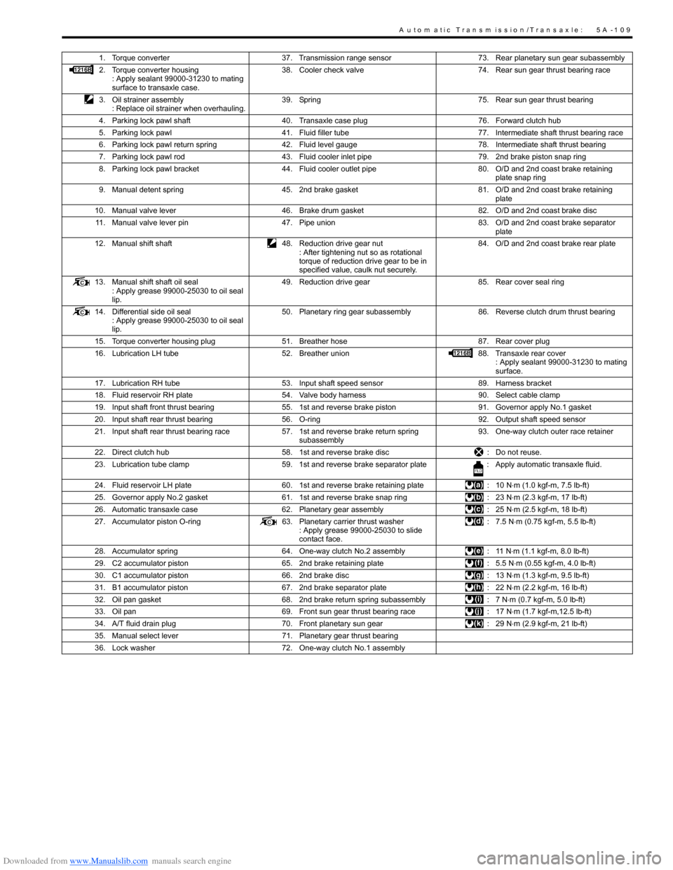
1. Torque converter37. Transmission range sensor 73. Rear planetary sun gear subassembly
2. Torque converter housing : Apply sealant 99000-31230 to mating
surface to transaxle case. 38. Cooler check valve
74. Rear sun gear thrust bearing race
3. Oil strainer assembly : Replace oil strainer when overhauling. 39. Spring
75. Rear sun gear thrust bearing
4. Parking lock pawl shaft 40. Transaxle case plug 76. Forward clutch hub
5. Parking lock pawl 41. Fluid filler tube 77. Intermediate shaft thrust bearing race
6. Parking lock pawl return spring 42. Fluid level gauge 78. Intermediate shaft thrust bearing
7. Parking lock pawl rod 43. Fluid cooler inlet pipe 79. 2nd brake piston snap ring
8. Parking lock pawl bracket 44. Fluid cooler outlet pipe 80. O/D and 2nd coast brake retaining
plate snap ring
9. Manual detent spring 45. 2nd brake gasket 81. O/D and 2nd coast brake retaining
plate
10. Manual valve lever 46. Brake drum gasket 82. O/D and 2nd coast brake disc
11. Manual valve lever pin 47. Pipe union 83. O/D and 2nd coast brake separator
plate
12. Manual shift shaft 48. Reduction drive gear nut
: After tightening nut so as rotational
torque of reduction drive gear to be in
specified value, caulk nut securely. 84. O/D and 2nd coast brake rear plate
13. Manual shift shaft oil seal : Apply grease 99000-25030 to oil seal
lip. 49. Reduction drive gear
85. Rear cover seal ring
14. Differential side oil seal : Apply grease 99000-25030 to oil seal
lip. 50. Planetary ring gear subassembly
86. Reverse clutch drum thrust bearing
15. Torque converter housing plug 51. Breather hose 87. Rear cover plug
16. Lubrication LH tube 52. Breather union 88. Transaxle rear cover
: Apply sealant 99000-31230 to mating
surface.
17. Lubrication RH tube 53. Input shaft speed sensor 89. Harness bracket
18. Fluid reservoir RH plate 54. Valve body harness 90. Select cable clamp
19. Input shaft front thrust bearing 55. 1st and reverse brake piston 91. Governor apply No.1 gasket
20. Input shaft rear thrust bearing 56. O-ring 92. Output shaft speed sensor
21. Input shaft rear thrust bearing race 57. 1st and reverse brake return spring
subassembly 93. One-way clutch outer race retainer
22. Direct clutch hub 58. 1st and reverse brake disc : Do not reuse.
23. Lubrication tube clamp 59. 1st and reverse brake separator plate : Apply automatic transaxle fluid.
24. Fluid reservoir LH plate 60. 1st and reverse brake retaining plate : 10 N⋅m (1.0 kgf-m, 7.5 lb-ft)
25. Governor apply No.2 gasket 61. 1st and reverse brake snap ring : 23 N⋅m (2.3 kgf-m, 17 lb-ft)
26. Automatic transaxle case 62. Planetary gear assembly : 25 N⋅m (2.5 kgf-m, 18 lb-ft)
27. Accumulator piston O-ring 63. Planetary carrier thrust washer
: Apply grease 99000-25030 to slide
contact face. : 7.5 N
⋅m (0.75 kgf-m, 5.5 lb-ft)
28. Accumulator spring 64. One-way clutch No.2 assembly : 11 N⋅m (1.1 kgf-m, 8.0 lb-ft)
29. C2 accumulator piston 65. 2nd brake retaining plate : 5.5 N⋅m (0.55 kgf-m, 4.0 lb-ft)
30. C1 accumulator piston 66. 2nd brake disc : 13 N⋅m (1.3 kgf-m, 9.5 lb-ft)
31. B1 accumulator piston 67. 2nd brake separator plate : 22 N⋅m (2.2 kgf-m, 16 lb-ft)
32. Oil pan gasket 68. 2nd brake return spring subassembly : 7 N⋅m (0.7 kgf-m, 5.0 lb-ft)
33. Oil pan 69. Front sun gear thrust bearing race : 17 N⋅m (1.7 kgf-m,12.5 lb-ft)
34. A/T fluid drain plug 70. Front planetary sun gear : 29 N⋅m (2.9 kgf-m, 21 lb-ft)
35. Manual select lever 71. Planetary gear thrust bearing
36. Lock washer 72. One-way clutch No.1 assembly
Page 755 of 1496

Downloaded from www.Manualslib.com manuals search engine Automatic Transmission/Transaxle: 5A-111
8) Remove fluid cooler pipes (1) and pipe union (2).
9) Remove fluid level gauge (3) and fluid filler tube (4).
10) Remove oil pan (1) and oil pan gasket (2).
NOTE
• For removal of oil pan, do not turn transaxle over as this will contaminate
valve body with foreign materials in
bottom of oil pan.
• When removing oil pan, tap around it lightly with plastic ha mmer. Do not force it
off by using screwdriver or the like.
11) Remove oil strain er assembly (1). 12) Disconnect connectors (2) from solenoid valves and
transmission fluid temperature sensor (1).
13) Remove valve body assembly bolts.
CAUTION!
Be careful not to let manual valve fall off
when removing valve body assembly.
NOTE
There are five kinds of bolts (bolts A (1), B (2),
C (3), D (4) and E (5)) fixing valve body
assembly.
14) Remove manual valve rod (1) from manual valve lever (2), then remove valve body assembly (3).
1 2
4
3
I3RM0B510059-01
I2RH0B510086-01
I2RH0B510087-01
1 2I4RS0A510027-01
I2RH0B510089-01
I2RH0B510090-01
Page 817 of 1496
Downloaded from www.Manualslib.com manuals search engine Manual Transmission/Transaxle: 5B-3
Diagnostic Information and Procedures
Manual Transaxle Symptom DiagnosisS7RS0B5204001
Repair Instructions
Manual Transaxle Oil ChangeS7RS0B5206001
1) Before changing or inspecting oil, be sure to stop engine and lift vehicle horizontally.
2) With vehicle lifted up, check oil level and leakage. If leakage exists, correct it.
NOTE
Whenever vehicle is hoisted for any other
service work than oil change, also be sure to
check for oil leakage.
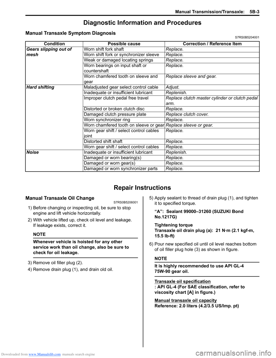
3) Remove oil filler plug (2).
4) Remove drain plug (1), and drain old oil. 5) Apply sealant to thread of drain plug (1), and tighten
it to specified torque.
“A”: Sealant 99000–31260 (SUZUKI Bond
No.1217G)
Tightening torque
Transaxle oil drain plug (a): 21 N·m (2.1 kgf-m,
15.5 lb-ft)
6) Pour new specified oil unt il oil level reaches bottom
of oil filler plug hole (3) as shown in figure.NOTE
It is highly recommended to use API GL-4
75W-90 gear oil.
Transaxle oil specification
: API GL-4 (For SAE classification, refer to
viscosity chart [A] in figure.)
Manual transaxle oil capacity
Reference: 2.0 liters (4.2/3.5 US/Imp. pt)
Condition Possible cause Correction / Reference Item
Gears slipping out of
mesh Worn shift fork shaft
Replace.
Worn shift fork or synchronizer sleeve Replace.
Weak or damaged locating springs Replace.
Worn bearings on input shaft or
countershaft Replace.
Worn chamfered tooth on sleeve and
gear Replace sleeve and gear.
Hard shifting Maladjusted gear select control cable Adjust.
Inadequate or insufficient lubricant Replenish.
Improper clutch pedal free travel Replace clutch master cylinder or clutch pedal
arm.
Distorted or broken clutch disc Replace.
Damaged clutch pressure plate Replace clutch cover.
Worn synchronizer ring Replace.
Worn chamfered tooth on sleeve or gear Replace sleeve or gear.
Worn gear shift / select control cables
joint Replace.
Distorted shift shaft Replace.
Worn gear shift / select control cables Replace.
Noise Inadequate or insufficient lubricant Replenish.
Damaged or worn bearing(s) Replace.
Damaged or worn gear(s) Replace.
Damaged or worn synchronizer parts Replace.
Page 818 of 1496
Downloaded from www.Manualslib.com manuals search engine 5B-4 Manual Transmission/Transaxle:
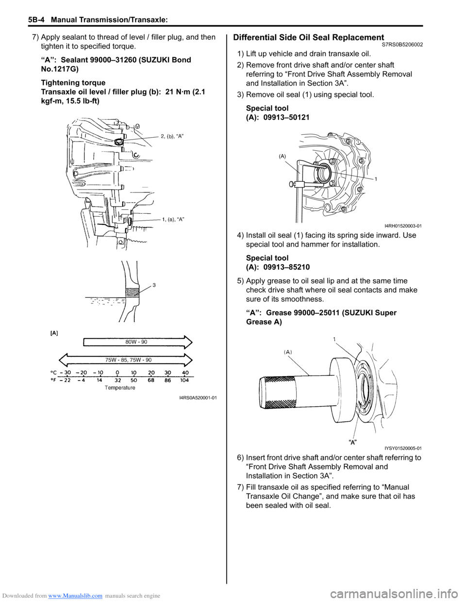
7) Apply sealant to thread of level / filler plug, and then
tighten it to specified torque.
“A”: Sealant 99000–31260 (SUZUKI Bond
No.1217G)
Tightening torque
Transaxle oil level / filler plug (b): 21 N·m (2.1
kgf-m, 15.5 lb-ft)Differential Side Oil Seal ReplacementS7RS0B5206002
1) Lift up vehicle and drain transaxle oil.
2) Remove front drive shaft and/or center shaft referring to “Front Driv e Shaft Assembly Removal
and Installation in Section 3A”.
3) Remove oil seal (1) using special tool.
Special tool
(A): 09913–50121
4) Install oil seal (1) facing its spring side inward. Use special tool and hammer for installation.
Special tool
(A): 09913–85210
5) Apply grease to oil seal lip and at the same time check drive shaft where oil seal contacts and make
sure of its smoothness.
“A”: Grease 99000–25011 (SUZUKI Super
Grease A)
6) Insert front drive shaft and/or center shaft referring to “Front Drive Shaft A ssembly Removal and
Installation in Section 3A”.
7) Fill transaxle oil as specified referring to “Manual Transaxle Oil Change”, and make sure that oil has
been sealed with oil seal.
I4RS0A520001-01
(A)
1
I4RH01520003-01
IYSY01520005-01
Page 827 of 1496
Downloaded from www.Manualslib.com manuals search engine Manual Transmission/Transaxle: 5B-13
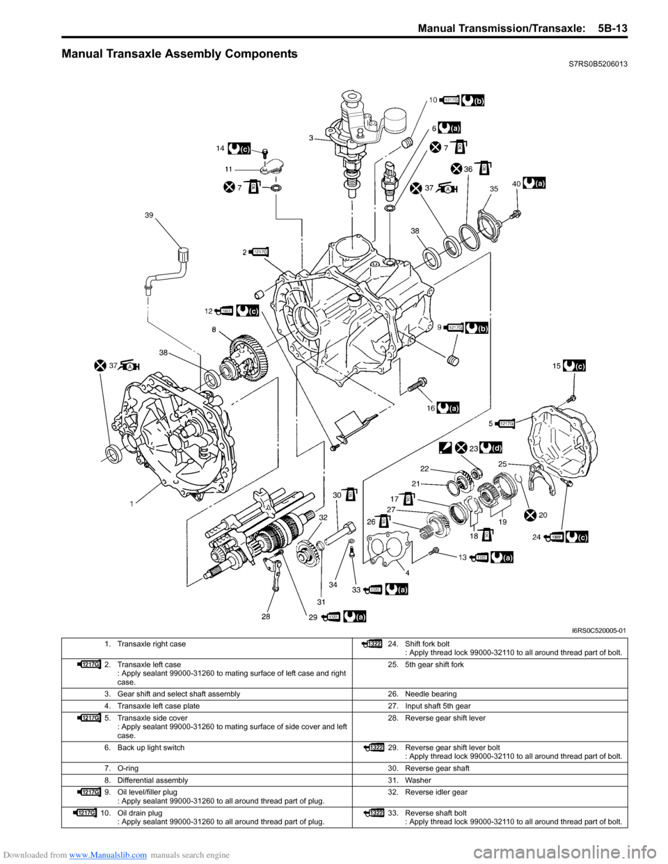
Manual Transaxle Assembly ComponentsS7RS0B5206013
I6RS0C520005-01
1. Transaxle right case 24. Shift fork bolt
: Apply thread lock 99000-32110 to all around thread part of bolt.
2. Transaxle left case : Apply sealant 99000-31260 to mating surface of left case and right
case. 25. 5th gear shift fork
3. Gear shift and select shaft assembly 26. Needle bearing
4. Transaxle left case plate 27. Input shaft 5th gear
5. Transaxle side cover : Apply sealant 99000-31260 to mating surface of side cover and left
case. 28. Reverse gear shift lever
6. Back up light switch 29. Reverse gear shift lever bolt
: Apply thread lock 99000-32110 to all around thread part of bolt.
7. O-ring 30. Reverse gear shaft
8. Differential assembly 31. Washer
9. Oil level/filler plug : Apply sealant 99000-31260 to all around thread part of plug. 32. Reverse idler gear
10. Oil drain plug : Apply sealant 99000-31260 to all around thread part of plug. 33. Reverse shaft bolt
: Apply thread lock 99000-32110 to all around thread part of bolt.
Page 849 of 1496
Downloaded from www.Manualslib.com manuals search engine Manual Transmission/Transaxle: 5B-35
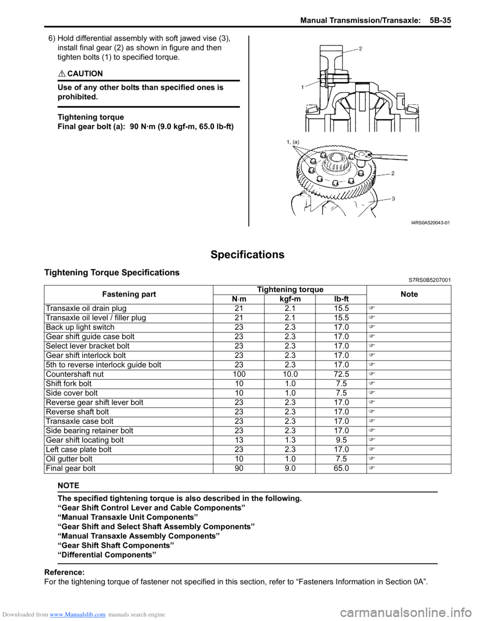
6) Hold differential assembly with soft jawed vise (3),
install final gear (2) as shown in figure and then
tighten bolts (1) to specified torque.
CAUTION!
Use of any other bolts than specified ones is
prohibited.
Tightening torque
Final gear bolt (a): 90 N·m (9.0 kgf-m, 65.0 lb-ft)
Specifications
Tightening Torque SpecificationsS7RS0B5207001
NOTE
The specified tightening torque is also described in the following.
“Gear Shift Control Leve r and Cable Components”
“Manual Transaxle Unit Components”
“Gear Shift and Select Shaft Assembly Components”
“Manual Transaxle Assembly Components”
“Gear Shift Shaft Components”
“Differential Components”
Reference:
For the tightening torque of fastener not specified in this section, refer to “Fasteners Information in Section 0A”.
I4RS0A520043-01
Fastening part Tightening torque
Note
N ⋅mkgf-mlb-ft
Transaxle oil drain plug 21 2.1 15.5 �)
Transaxle oil level / filler plug 21 2.1 15.5 �)
Back up light switch 23 2.3 17.0 �)
Gear shift guide case bolt 23 2.3 17.0 �)
Select lever bracket bolt 23 2.3 17.0 �)
Gear shift interlock bolt 23 2.3 17.0 �)
5th to reverse interlock guide bolt 23 2.3 17.0 �)
Countershaft nut 100 10.0 72.5 �)
Shift fork bolt 10 1.0 7.5 �)
Side cover bolt 10 1.0 7.5 �)
Reverse gear shift lever bolt 23 2.3 17.0 �)
Reverse shaft bolt 23 2.3 17.0 �)
Transaxle case bolt 23 2.3 17.0 �)
Side bearing retainer bolt 23 2.3 17.0 �)
Gear shift locating bolt 13 1.3 9.5 �)
Left case plate bolt 23 2.3 17.0 �)
Oil gutter bolt 10 1.0 7.5 �)
Final gear bolt 90 9.0 65.0 �)
Page 853 of 1496
Downloaded from www.Manualslib.com manuals search engine Clutch: 5C-1
Transmission / Transaxle
Clutch
General Description
Clutch ConstructionS7RS0B5301001
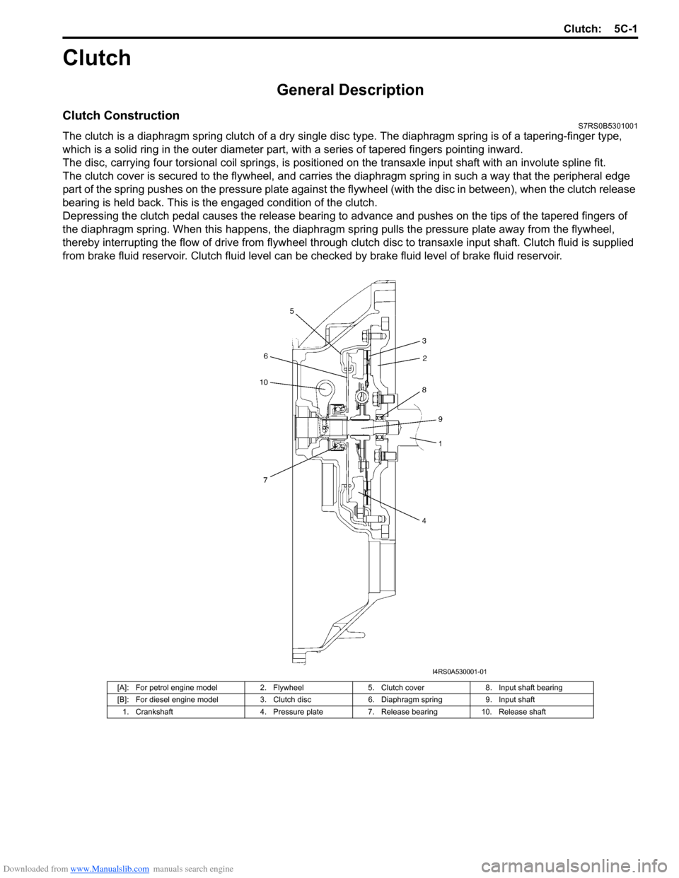
The clutch is a diaphragm spring clutch of a dry single disc type. The diaphragm spring is of a tapering-finger type,
which is a solid ring in the outer diameter part, with a series of tapered fingers pointing inward.
The disc, carrying four torsional coil springs, is positione d on the transaxle input shaft with an involute spline fit.
The clutch cover is secured to the flywheel, and carries the diaphragm spring in such a way that the peripheral edge
part of the spring pushes on the pressure plate against the flywheel (with the disc in between), when the clutch release
bearing is held back. This is the engaged condition of the clutch.
Depressing the clutch pedal c auses the release bearing to advance and pushes on the tips of the tapered fingers of
the diaphragm spring. When this happens, the diaphragm sp ring pulls the pressure plate away from the flywheel,
thereby interrupting the flow of drive from flywheel through clutch disc to transaxle input shaft. Clutch fluid is supplied
from brake fluid reservoir. Clutch fluid level can be checked by brake fluid level of brake fluid reservoir.
[A]: For petrol engine model2. Flywheel5. Clutch cover 8. Input shaft bearing
[B]: For diesel engine model 3. Clutch disc6. Diaphragm spring 9. Input shaft
1. Crankshaft 4. Pressure plate7. Release bearing 10. Release shaft
I4RS0A530001-01
Page 1168 of 1496

Downloaded from www.Manualslib.com manuals search engine 9-ii Table of Contents
List of Connectors ........................................... 9A-103
C Connector .................................................... 9A-103
D Connector (M16A engine) ........................... 9A-104
E Connector .................................................... 9A-104
G Connector .................................................... 9A-106
J Connector ..................................................... 9A-108
K Connector .................................................... 9A-109
L Connector..................................................... 9A-109
M Connector (SPORT model) ......................... 9A-111
O Connector .................................................... 9A-111
R Connector .................................................... 9A-111
Lighting Systems .................................... 9B-1
Component Location ........... ................................9B-1
Lighting System Component s Location............... 9B-1
Interior Light System Location............................. 9B-2
Diagnostic Information and Procedures ............ 9B-2 Headlight Symptom Diagnosis ............................ 9B-2
Headlight Leveling System Symptom Diagnosis (If Equipped) ..................................... 9B-2
Turn Signal and Hazard Warning Light Symptom Diagnosis .......................................... 9B-3
Clearance, Tail and License Plate Light Symptom Diagnosis .......................................... 9B-3
Back-Up Light Symptom Diagnosis..................... 9B-4
Brake Light Symptom Diagnosis ......................... 9B-4
Front Fog Light Symptom Diagnosis (If Equipped) .......................................................... 9B-4
Interior Light Symptom Diagnosis ....................... 9B-5
Repair Instructions ..............................................9B-5 Headlight Housing Removal and Installation ...... 9B-5
Headlight Bulb Replacemen t............................... 9B-6
Headlight Aiming Adjustment with Screen .......... 9B-6
Headlight Switch (in Lighting Switch) Removal and Installation ................................... 9B-8
Headlight Switch (in Lighting Switch) Inspection .......................................................... 9B-8
Hazard Warning Switch Removal and Installation ......................................................... 9B-8
Hazard Warning Switch Inspection ..................... 9B-9
Brake Light Switch Inspection ............................. 9B-9
Turn Signal Light Switch (in Lighting Switch) Removal and Installation ................................... 9B-9
Turn Signal Light Switch (in Lighting Switch) Inspection .......................................................... 9B-9
Turn Signal and Hazard Warning Relay Removal and Installation ................................... 9B-9
Turn Signal and Hazard Warning Relay Inspection ........................................................ 9B-10
License Light Removal and Installation............. 9B-10
Front Fog Light Removal and Installation (If Equipped) ........................................................ 9B-11
Front Fog Light Bulb Replacement (If Equipped) ........................................................ 9B-11
Front Fog Light Switch Inspection (If Equipped) ........................................................ 9B-11
Front Fog Light Relay Inspection (If Equipped) ........................................................ 9B-11
Front Fog Light Aiming Adjustment with Screen (If Equipped) ....................................... 9B-12 Headlight Leveling Switch Inspection (If
Equipped) ........................................................ 9B-13
Headlight Leveling Actuator Inspection (If Equipped) ........................................................ 9B-13
Instrumentation / Driver Info. / Horn ...... 9C-1
Precautions ...........................................................9C-1 Precautions in Diagnosing Troubles for Combination Meter ............................................9C-1
General Description .............................................9C-1 CAN Communication System Description...........9C-1
Auto Volume Co ntrol System Description (If
Equipped) ..........................................................9C-3
Schematic and Routing Diagram ........................9C-4 Combination Meter Circuit Diagram ....................9C-4
Component Location ............ ...............................9C-6
Audio System Component Location ....................9C-6
Diagnostic Information and Procedures ............9C-6 Speedometer and VSS Symp tom Diagnosis ......9C-6
Tachometer Symptom Diagnosis ........................9C-6
Engine Coolant Temperature (ECT) Meter Symptom Diagnosis ..........................................9C-7
Fuel Meter Symptom Diagnosis ..........................9C-7
Low Fuel Warning Light Symptom Diagnosis .....9C-7
Oil Pressure Warning Light Symptom Diagnosis ..........................................................9C-8
Brake and Parking Brake Warning Light Symptom Diagnosis ..........................................9C-8
Seat Belt Reminder Light Symptom Diagnosis (If Equipped)......................................................9C-8
A/T Shift Position Indicator Symptom Diagnosis (A/T Model).......................................9C-9
Charge Warning Light Sy mptom Diagnosis ........9C-9
Main Beam (High Beam) Indicator Symptom Diagnosis ..........................................................9C-9
Warning Buzzer Circuit Sy mptom Diagnosis ....9C-10
Cigarette Lighter Symptom Diagnosis (If Equipped) ........................................................9C-10
Horn Symptom Diagnosis .................................9C-10
Information Display Symptom Diagnosis (If Equipped) ........................................................9C-11
Clock Symptom Diagnosis (If Equipped)...........9C-12
Audio System Symptom Diagnosis (If Equipped) ........................................................9C-12
Remote Audio Control Switch Symptom Diagnosis (If Equipped) ...................................9C-13
Navigation Symptom Diagnosis (If Equipped)...9C-14
Repair Instructions ............ ................................9C-14
Ignition Switch Removal and Installation...........9C-14
Ignition Switch Inspection..................................9C-14
Combination Meter Removal and Installation ...9C-15
Fuel Level Sensor Removal and Installation .....9C-15
Fuel Level Sensor Inspection ............................9C-15
Oil Pressure Switch Remova l and Installation ..9C-15
Oil Pressure Switch Inspec tion .........................9C-16
Engine Coolant Temperature (ECT) Sensor Inspection ........................................................9C-16
Brake Fluid Level Switch Inspection .................9C-16
Parking Brake Switch Inspec tion.......................9C-16