outside air SUZUKI SWIFT 2008 2.G Service Owner's Manual
[x] Cancel search | Manufacturer: SUZUKI, Model Year: 2008, Model line: SWIFT, Model: SUZUKI SWIFT 2008 2.GPages: 1496, PDF Size: 34.44 MB
Page 1169 of 1496

Downloaded from www.Manualslib.com manuals search engine Table of Contents 9-iii
Door Switch (Front / Rear Door) Inspection ...... 9C-17
Rear End Door Switch Inspection ..................... 9C-17
Outside Air Temperature Sensor Removal and Installation (If Equipped) .......................... 9C-17
Outside Air Temperature Sensor Inspection (If Equipped) ................................................... 9C-17
Instrument Panel Removal and Installation....... 9C-18
Information Display (Clock) Removal and Installation ....................................................... 9C-19
Audio Unit Removal and In stallation ................. 9C-19
Front Speaker Removal and Installation ........... 9C-19
Rear Speaker Removal and Installation............ 9C-20
Horn Removal and Installation .......................... 9C-20
Horn Inspection ................................................. 9C-20
Horn Relay Inspection ....................................... 9C-20
Antenna Amplifier Removal and Installation ..... 9C-21
Remote Audio Control Switch Removal and Installation (If Equipped) ................................. 9C-21
Remote Audio Control Switch Inspection (If Equipped)........................................................ 9C-22
Vehicle Speed Signal Inspection (For Audio Unit) (If Equipped) ........................................... 9C-22
Specifications ..................................................... 9C-22
Tightening Torque Specifications ...................... 9C-22
Wipers / Washers............ ......................... 9D-1
Diagnostic Information and Procedures ............ 9D-1
Front Wiper and Washer Symptom Diagnosis .... 9D-1
Rear Wiper and Washer Symptom Diagnosis..... 9D-1
Repair Instructions .............................................. 9D-2 Wipers and Washers Components ..................... 9D-2
Washer Tank and Washer Pump Removal and Installation .................................................. 9D-3
Washer Pump Inspection .................................... 9D-3
Windshield Wiper Removal and Installation ........ 9D-4
Windshield Wiper Motor Inspection..................... 9D-5
Rear Wiper Removal and Installation.................. 9D-6
Rear Wiper Motor Inspection .............................. 9D-7
Windshield Wiper and Washer Switch Removal and Installation................................... 9D-7
Windshield Wiper and Washer Switch Inspection.......................................................... 9D-8
Rear Wiper and Washer Switch Removal and Installation ......................................................... 9D-9
Rear Wiper and Washer Switch Inspection......... 9D-9
Rear Wiper Relay Removal and Installation ..... 9D-10
Rear Wiper Relay Inspection ............................ 9D-10
Specifications ..................................................... 9D-10
Tightening Torque Specifications ...................... 9D-10
Glass / Windows / Mirrors.. ..................... 9E-1
General Description ............................................. 9E-1
Rear End Door Window Defogger System Description ........................................................ 9E-1
Windshield Construction ..................................... 9E-1
Diagnostic Information and Procedures ............ 9E-2 Rear End door Window Defogger Symptom Diagnosis .......................................................... 9E-2 Power Window Control System Symptom
Diagnosis .......................................................... 9E-2
Power Door Mirror Control System Symptom Diagnosis .......................................................... 9E-3
Door Mirror Heater Symptom Diagnosis (If
Equipped) .......................................................... 9E-3
Repair Instructions ........... ................................... 9E-4
Windshield Removal and In stallation .................. 9E-4
Front Door Window Components ........................ 9E-8
Front Door Glass Removal and Installation ........ 9E-8
Front Door Window Re gulator Removal and
Installation ......................................................... 9E-9
Front Door Window Regula tor Inspection ......... 9E-10
Rear Door Window Components ...................... 9E-10
Rear Door Glass Removal and Installation ....... 9E-11
Rear Door Window Regulator Removal and Installation ....................................................... 9E-12
Rear Door Window Regulato r Inspection .......... 9E-12
Rear End Door Window Components ............... 9E-13
Rear End Door Glass Removal and Installation ....................................................... 9E-13
Rear End Door Window Defogger Switch Inspection ........................................................ 9E-14
Rear End Door Window Defogger Relay Inspection ........................................................ 9E-14
Rear End Door Window Defogger Wire Inspection ........................................................ 9E-15
Rear End Door Window Defogger Wire
Repair.............................................................. 9E-15
Power Window Main Switch Inspection ............ 9E-16
Power Window Sub Switch Inspection .............. 9E-17
Door Mirror Components.. ................................. 9E-18
Door Mirror Removal and In stallation................ 9E-18
Power Door Mirror Switch Inspection ................ 9E-18
Power Door Mirror Actuator Inspection ............. 9E-19
Door Mirror Heater Switch Inspection (If Equipped) ........................................................ 9E-19
Door Mirror Heater Inspec tion (If Equipped) ..... 9E-19
Special Tools and Equipmen t ........................... 9E-19
Recommended Service Material ....................... 9E-19
Security and Locks......... ..........................9F-1
General Description ............................................. 9F-1
Key Coding Construction .................................... 9F-1
Rear End Door Opener System Description ....... 9F-1
Component Location ............ ............................... 9F-2
Power Door Lock and Keyless Entry System
Component Location ......................................... 9F-2
Diagnostic Information and Procedures ............ 9F-3 Power Door Lock System Symptom Diagnosis .......................................................... 9F-3
Power Door Lock System Operation Inspection .......................................................... 9F-3
Keyless Entry System Symptom Diagnosis (If
Equipped) .......................................................... 9F-4
Keyless Entry System Operation Inspection ....... 9F-5
Door Lock Function of Keyless Start System Symptom Diagnosis (If Equipped)..................... 9F-5
Page 1185 of 1496

Downloaded from www.Manualslib.com manuals search engine Wiring Systems: 9A-14
E: Main harness (RHD)
E: Main harness
56
E06E12
E03or
E85
E07
E09
E08
E13
E10
E11E05 E04
E01 E02
E19
7
22
E34E31
E32
E57
E24
(TO C36)
E33
E36
E35
E30
E29
E28
E20
E21
E22
E27
E26
E23
E25E17E56
E18
E14 E15
E55
E
I7RS0B910902-02
No./Color
Connective position No./ColorConnective position
E01/GRY Windshield wiper motor E22/N Front position light (L)
E02/GRY Brake fluid level switch E23/GRY ECM
E03/BLK ABS control module E24/N Engine Harness (To C36)
E04/BLK A/C pressure sensor E25/BLK Wheel speed sensor (FL)
E05/BLK Wheel speed sensor (FR) E26/N Main fuse box
E06/N Side turn signal light (R) E27/BLK Main fuse box
E07/N Front position light (R) E28/BLK Radiator fan relay #1
E08/BLK Head light (R) E29/BLK Radiator fan relay #2
E09/GRY Front turn signal light (R) E30/BLK Radiator fan relay #3
E10/GRN Rear washer motor E31/BLK Starting motor relay
E11/BLU Windshield washer motor E32/BLK Main relay
E12/BLK (IF EQPD) Front fog light (R)
E33/BLK A/T relay
E13/YEL Forward sensor E34/BLK (IF
EQPD) Front fog light relay
E14/BLK Outside air temperature sensor E35/BLK Fuel pump relay
E15/BLK Horn E36/BLK A/C compressor relay
E17/BLK Radiator fan motor E55/- Weld splice
E18/BLK (IF EQPD) Front fog light (L) E56/BLK
(M16A
engine) Throttle actuator control relay
E19/N Side turn signal light (L) E57/BLK Diagnosis connector #1
E20/GRY Front turn signal light (L) E85/BLK (IF
EQPD) ESP
® control module
E21/BLK Headlight (R)
Page 1186 of 1496
Downloaded from www.Manualslib.com manuals search engine 9A-15 Wiring Systems:
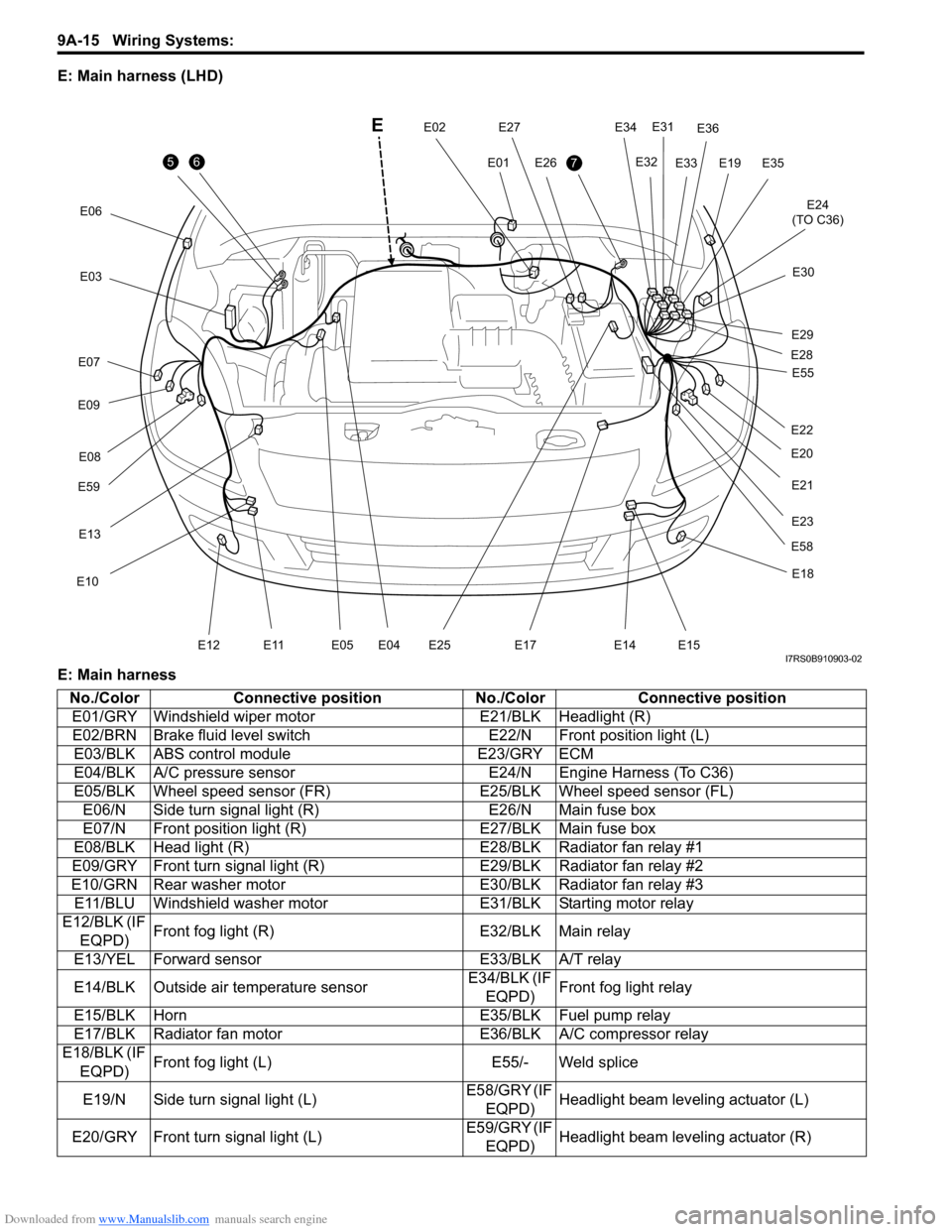
E: Main harness (LHD)
E: Main harness
56
E06E12
E
E03
E07
E09
E59E08
E13
E10
E11E05 E04
E01
E02E197
E34
E31
E32
E24
(TO C36)
E33
E36
E35
E30
E29
E28
E20
E21
E22
E58
E27
E26
E23
E25E17
E18
E14 E15
E55
I7RS0B910903-02
No./Color
Connective position No./ColorConnective position
E01/GRY Windshield wiper motor E21/BLK Headlight (R)
E02/BRN Brake fluid level switch E22/N Front position light (L)
E03/BLK ABS control module E23/GRY ECM
E04/BLK A/C pressure sensor E24/N Engine Harness (To C36)
E05/BLK Wheel speed sensor (FR) E25/BLK Wheel speed sensor (FL)
E06/N Side turn signal light (R) E26/N Main fuse box
E07/N Front position light (R) E27/BLK Main fuse box
E08/BLK Head light (R) E28/BLK Radiator fan relay #1
E09/GRY Front turn signal light (R) E29/BLK Radiator fan relay #2
E10/GRN Rear washer motor E30/BLK Radiator fan relay #3
E11/BLU Windshield washer motor E31/BLK Starting motor relay
E12/BLK (IF EQPD) Front fog light (R)
E32/BLK Main relay
E13/YEL Forward sensor E33/BLK A/T relay
E14/BLK Outside air temperature sensor E34/BLK (IF
EQPD) Front fog light relay
E15/BLK Horn E35/BLK Fuel pump relay
E17/BLK Radiator fan motor E36/BLK A/C compressor relay
E18/BLK (IF
EQPD) Front fog light (L)
E55/- Weld splice
E19/N Side turn signal light (L) E58/GRY (IF
EQPD) Headlight beam leveling actuator (L)
E20/GRY Front turn signal light (L) E59/GRY (IF
EQPD) Headlight beam leveling actuator (R)
Page 1230 of 1496
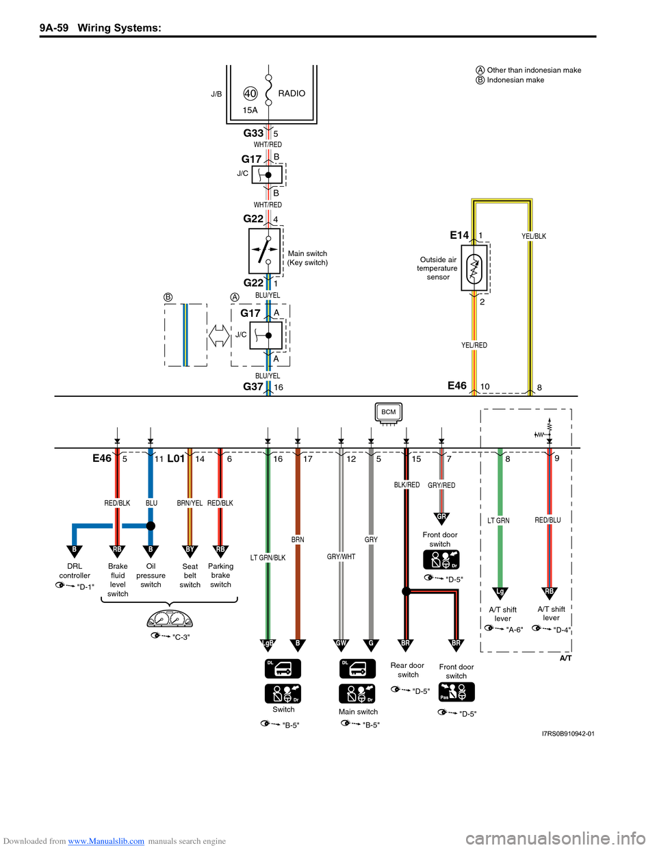
Downloaded from www.Manualslib.com manuals search engine 9A-59 Wiring Systems:
9
15 7
"D-5"
"A-6"
A/T
GRY/RED
RED/BLU
16
A A
B
BG37
BLU/YEL
BLU/YEL
J/C
G17
J/C
G17
G22
G22
1
4
Main switch
(Key switch)
RADIO
G335
15A
40
WHT/RED
WHT/RED
YEL/RED
YEL/BLK1E14
2
Outside air
temperature sensor
"B-5"
Switch
6L0114
1617125
RED/BLKBRN/YEL
LT GRN/BLK
BRN
GRY/WHT
GRY
Parking
brake
switch
Seat
belt
switch
"C-3"
"D-1"
RBBY
8
LT GRN
A/T shift lever A/T shift
lever
115
"D-4"
LgRB
GR
Oil
pressure switchBrakefluid
level
switch
B
DRL
controller
B
E46
10E468
LgBBGWG
Main switch
"B-5"
Front door switch
Front door switch
Rear door switch
"D-5"
"D-5"
BRBR
BLK/RED
J/B
BCM
BLURED/BLK
RB
Other than indonesian make
Indonesian make
A
AB
B
I7RS0B910942-01
Page 1273 of 1496
Downloaded from www.Manualslib.com manuals search engine Wiring Systems: 9A-102
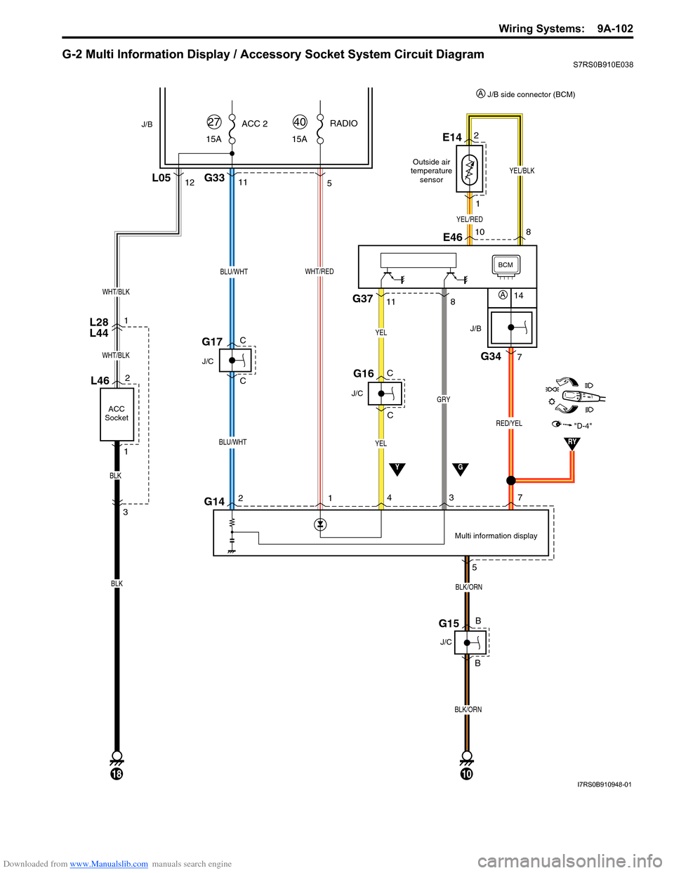
G-2 Multi Information Display / Accessory Socket System Circuit DiagramS7RS0B910E038
11
BLU/WHT
BLU/WHT
15AACC 2
27
J/C
G17
L28
L44
YG
Multi information display
J/B
BCM
J/B
G34
7
14
RED/YEL
10
BLK/ORN
2
BLK/ORN
15A RADIO
40
G335
WHT/RED
G141
3
J/C
YEL
YEL
G16
4
57
G15
J/C
12L05
WHT/BLK
L46
ACC
Socket
2
1
18
WHT/BLK
BLK
BLK
3 1
C
C
B
B
C
C
GRY
G378
11
"D-4"
RY
YEL/RED
YEL/BLK
2E14
1
8
10E46
A
J/B side connector (BCM)
A
Outside air
temperature sensor
I7RS0B910948-01
Page 1306 of 1496
Downloaded from www.Manualslib.com manuals search engine 9C-11 Instrumentation / Driver Info. / Horn:
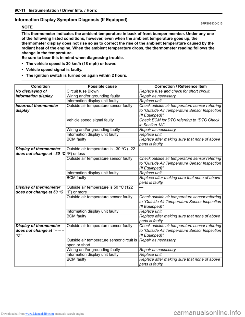
Information Display Symptom Diagnosis (If Equipped)S7RS0B9304015
NOTE
This thermometer indicates the ambient temperature in back of front bumper member. Under any one
of the following listed conditions, however, even when the ambient temperature goes up, the
thermometer display does not rise so as to correct the rise of the ambient temperature caused by the
radiant heat of the engine. When the ambient temperature drops, the thermometer reading follows the
change in the temperature.
Be sure to bear this in mind when diagnosing trouble.
• The vehicle speed is 30 km/h (18 mph) or lower.
• Vehicle speed signal is faulty.
• The ignition switch is turned on again within 2 hours.
ConditionPossible cause Correction / Reference Item
No displaying of
information display Circuit fuse Blown
Replace fuse and check for short circuit.
Wiring and/or grounding faulty Repair as necessary.
Information display unit faulty Replace unit.
Incorrect thermometer
display Outside air temperature sensor faulty
Check outside air temperature sensor referring
to “Outside Air Temperature Sensor Inspection
(If Equipped)”.
Vehicle speed signal faulty Check ECM for DTC referring to “DTC Check
in Section 1A”.
Wiring and/or grounding faulty Repair as necessary.
Information display unit faulty Replace unit.
BCM faulty Replace after making sure that none of above
parts is faulty.
Display of thermometer
does not change at –30
°C Outside air temperature is –30
°C (–22
° F) or less —
Outside air temperature sensor faulty Check outside air temperature sensor referring
to “Outside Air Temperature Sensor Inspection
(If Equipped)”.
Information display unit faulty Replace unit.
BCM faulty Replace after making sure that none of above
parts is faulty.
Display of thermometer
does not change at 50
°C Outside air temperature is 50
°C (122
° F) or more —
Outside air temperature sensor faulty Check outside air temperature sensor referring
to “Outside Air Temperature Sensor Inspection
(If Equipped)”.
Information display unit faulty Replace unit.
BCM faulty Replace after making sure that none of above
parts is faulty.
Display of thermometer
does not change at “– – –
°C” Outside air temperature sensor faulty
Check outside air temperature sensor referring
to “Outside Air Temperature Sensor Inspection
(If Equipped)”.
Outside air temperature sensor circuit is
open or short Repair as necessary.
Wiring and/or grounding faulty Repair as necessary.
Information display unit faulty Replace unit.
BCM faulty Replace after making sure that none of above
parts is faulty.
Page 1312 of 1496
Downloaded from www.Manualslib.com manuals search engine 9C-17 Instrumentation / Driver Info. / Horn:
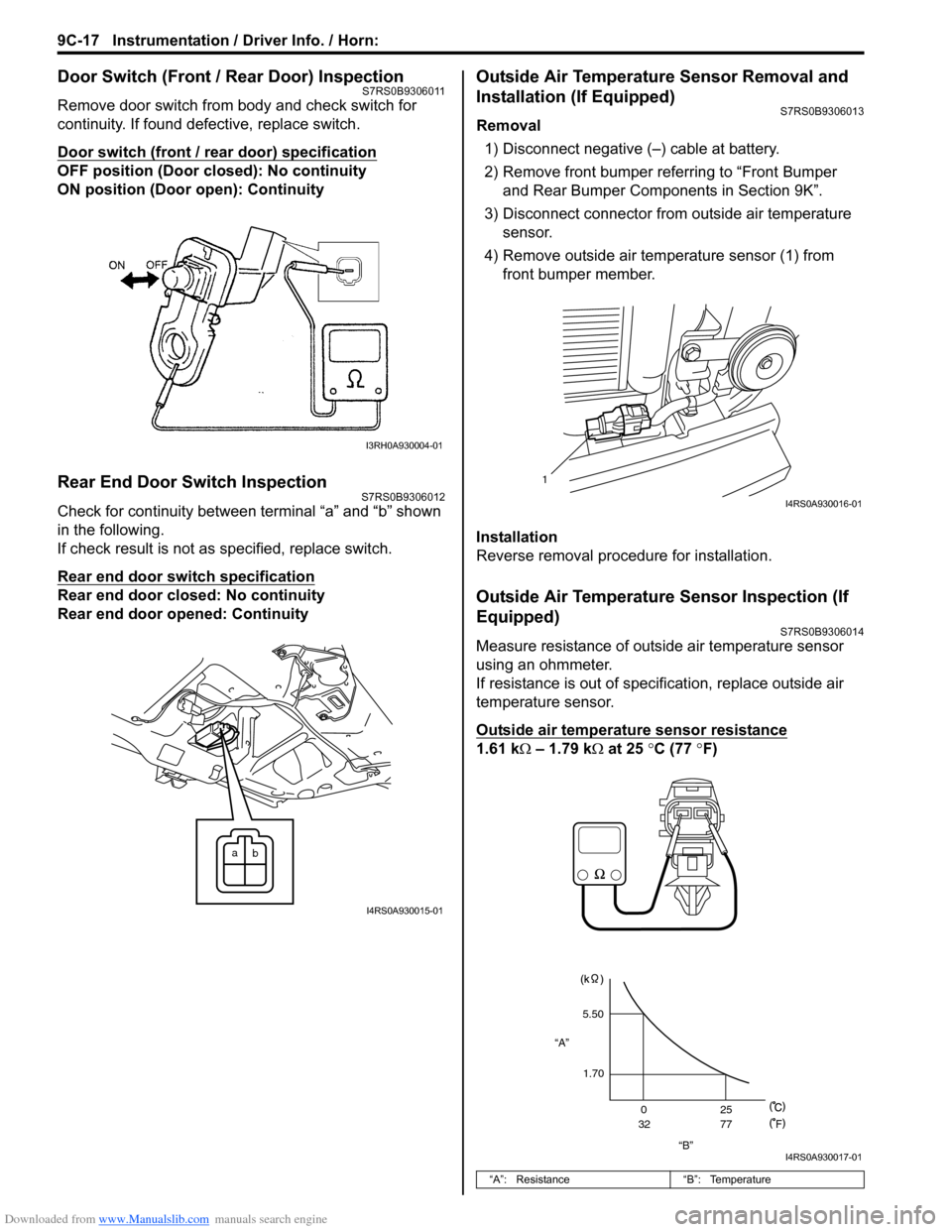
Door Switch (Front / Rear Door) InspectionS7RS0B9306011
Remove door switch from body and check switch for
continuity. If found defective, replace switch.
Door switch (front / rear door) specification
OFF position (Door closed): No continuity
ON position (Door open): Continuity
Rear End Door Switch InspectionS7RS0B9306012
Check for continuity between terminal “a” and “b” shown
in the following.
If check result is not as specified, replace switch.
Rear end door switch specification
Rear end door closed: No continuity
Rear end door opened: Continuity
Outside Air Temperature Sensor Removal and
Installation (If Equipped)
S7RS0B9306013
Removal
1) Disconnect negative (–) cable at battery.
2) Remove front bumper referring to “Front Bumper and Rear Bumper Components in Section 9K”.
3) Disconnect connector from outside air temperature sensor.
4) Remove outside air temperature sensor (1) from front bumper member.
Installation
Reverse removal procedure for installation.
Outside Air Temperature Sensor Inspection (If
Equipped)
S7RS0B9306014
Measure resistance of outside air temperature sensor
using an ohmmeter.
If resistance is out of specif ication, replace outside air
temperature sensor.
Outside air temperature sensor resistance
1.61 kΩ – 1.79 k Ω at 25 °C (77 °F)
I3RH0A930004-01
a
b
I4RS0A930015-01
“A”: Resistance “B”: Temperature
1
I4RS0A930016-01
“B”
“A”
5.50
1.70 0
32 25
77
F
I4RS0A930017-01
Page 1331 of 1496
Downloaded from www.Manualslib.com manuals search engine Glass / Windows / Mirrors: 9E-4
Repair Instructions
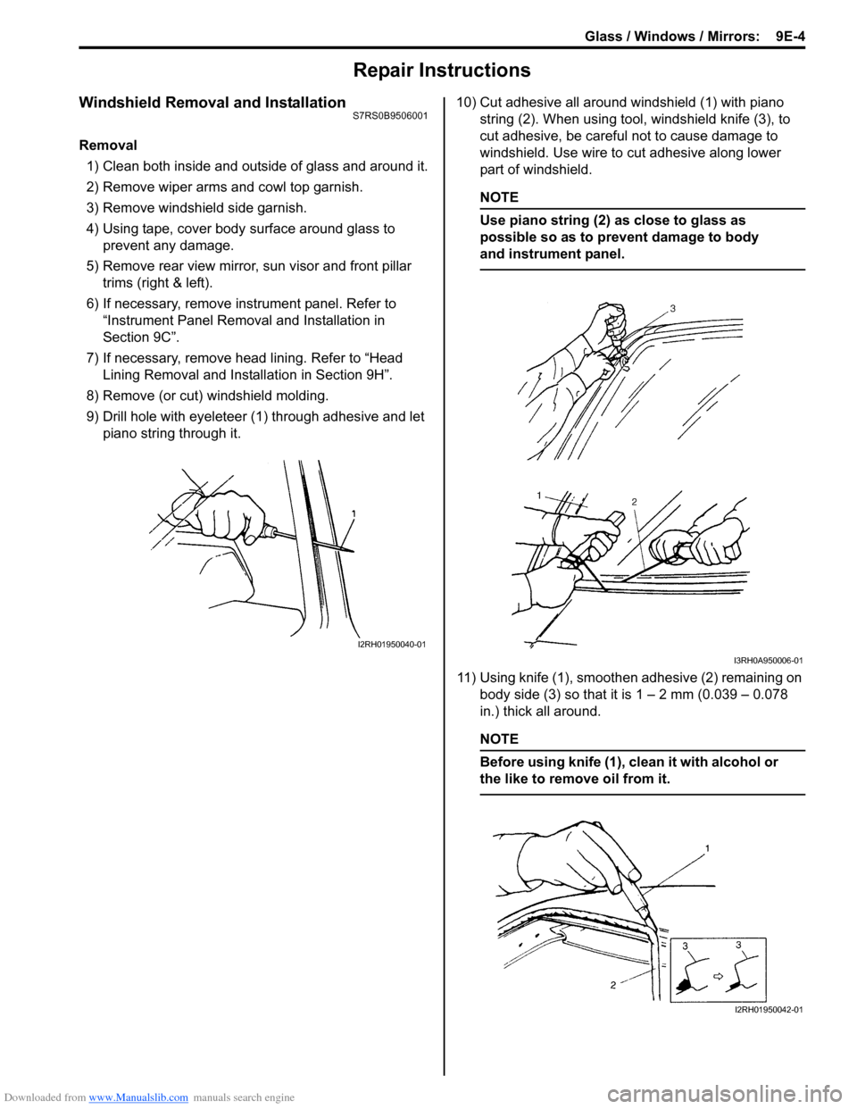
Windshield Removal and InstallationS7RS0B9506001
Removal1) Clean both inside and outside of glass and around it.
2) Remove wiper arms and cowl top garnish.
3) Remove windshield side garnish.
4) Using tape, cover body surface around glass to prevent any damage.
5) Remove rear view mirror , sun visor and front pillar
trims (right & left).
6) If necessary, remove instrument panel. Refer to “Instrument Panel Removal and Installation in
Section 9C”.
7) If necessary, remove he ad lining. Refer to “Head
Lining Removal and Installation in Section 9H”.
8) Remove (or cut) windshield molding.
9) Drill hole with eyeleteer (1 ) through adhesive and let
piano string through it. 10) Cut adhesive all around windshield (1) with piano
string (2). When using tool, windshield knife (3), to
cut adhesive, be careful not to cause damage to
windshield. Use wire to cut adhesive along lower
part of windshield.
NOTE
Use piano string (2) as close to glass as
possible so as to prevent damage to body
and instrument panel.
11) Using knife (1), smoothen adhesive (2) remaining on body side (3) so that it is 1 – 2 mm (0.039 – 0.078
in.) thick all around.
NOTE
Before using knife (1), clean it with alcohol or
the like to remove oil from it.
I2RH01950040-01
I3RH0A950006-01
I2RH01950042-01
Page 1351 of 1496
Downloaded from www.Manualslib.com manuals search engine Security and Locks: 9F-5
Keyless Entry System Operation InspectionS7RS0B9604004
NOTE
When performing the this inspection, make
sure to have any of the door once opened/
closed after the ignition key has been
removed from the ignition key cylinder.
1) Confirm that power door lock system operates normally, refer to “Power Door Lock System
Operation Inspection”.
2) All doors are closed and unlocked.
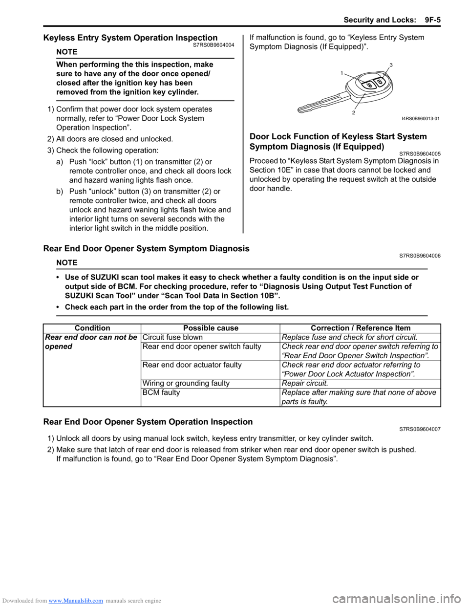
3) Check the following operation: a) Push “lock” button (1 ) on transmitter (2) or
remote controller once, and check all doors lock
and hazard waning lights flash once.
b) Push “unlock” button (3) on transmitter (2) or remote controller twice, and check all doors
unlock and hazard waning lights flash twice and
interior light turns on several seconds with the
interior light switch in the middle position. If malfunction is found, go to “Keyless Entry System
Symptom Diagnosis (If Equipped)”.
Door Lock Function of Keyless Start System
Symptom Diagnosis (If Equipped)
S7RS0B9604005
Proceed to “Keyless Start System Symptom Diagnosis in
Section 10E” in case that doors cannot be locked and
unlocked by operating the request switch at the outside
door handle.
Rear End Door Opener System Symptom DiagnosisS7RS0B9604006
NOTE
• Use of SUZUKI scan tool makes it easy to check wh
ether a faulty condition is on the input side or
output side of BCM. For checking procedure, re fer to “Diagnosis Using Output Test Function of
SUZUKI Scan Tool” under “Scan Tool Data in Section 10B”.
• Check each part in the order from the top of the following list.
Rear End Door Opener System Operation InspectionS7RS0B9604007
1) Unlock all doors by using manu al lock switch, keyless entry transmitter, or key cylinder switch.
2) Make sure that latch of rear end door is released from striker when rear end door opener switch is pushed. If malfunction is found, go to “Rear End Door Opener System Symptom Diagnosis”.
1
3
2I4RS0B960013-01
ConditionPossible cause Correction / Reference Item
Rear end door can not be
opened Circuit fuse blown
Replace fuse and check for short circuit.
Rear end door opener switch faulty Check rear end door opener switch referring to
“Rear End Door Opener Switch Inspection”.
Rear end door actuator faulty Check rear end door actuator referring to
“Power Door Lock Actuator Inspection”.
Wiring or grounding faulty Repair circuit.
BCM faulty Replace after making sure that none of above
parts is faulty.
Page 1352 of 1496
Downloaded from www.Manualslib.com manuals search engine 9F-6 Security and Locks:
Repair Instructions
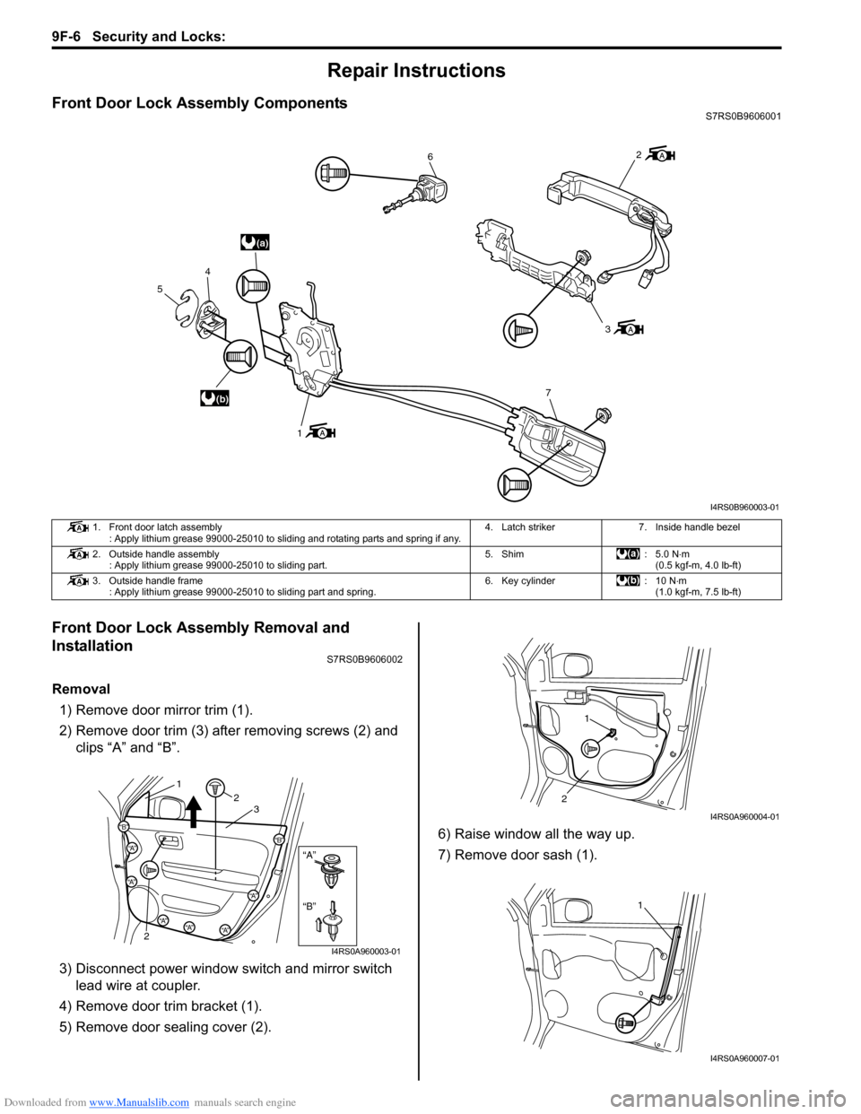
Front Door Lock Assembly ComponentsS7RS0B9606001
Front Door Lock Assembly Removal and
Installation
S7RS0B9606002
Removal1) Remove door mirror trim (1).
2) Remove door trim (3) after removing screws (2) and clips “A” and “B”.
3) Disconnect power window s witch and mirror switch
lead wire at coupler.
4) Remove door trim bracket (1).
5) Remove door sealing cover (2). 6) Raise window all the way up.
7) Remove door sash (1).
(a)
(b)
6
3
7
1
4
5
2
I4RS0B960003-01
1. Front door latch assembly : Apply lithium grease 99000-25010 to sliding and rotating parts and spring if any. 4. Latch striker 7. Inside handle bezel
2. Outside handle assembly : Apply lithium grease 99000-25010 to sliding part. 5. Shim : 5.0 N
⋅m
(0.5 kgf-m, 4.0 lb-ft)
3. Outside handle frame : Apply lithium grease 99000-25010 to sliding part and spring. 6. Key cylinder : 10 N⋅m
(1.0 kgf-m, 7.5 lb-ft)
“B”
“A”
“B”
“A”
“B”“A”
“A”
“A”“A”“A”
12
2 3
I4RS0A960003-01
1
2
I4RS0A960004-01
1
I4RS0A960007-01