WIRE SUZUKI SWIFT 2008 2.G Service Workshop Manual
[x] Cancel search | Manufacturer: SUZUKI, Model Year: 2008, Model line: SWIFT, Model: SUZUKI SWIFT 2008 2.GPages: 1496, PDF Size: 34.44 MB
Page 1414 of 1496
Downloaded from www.Manualslib.com manuals search engine 10B-11 Body Electrical Control System:
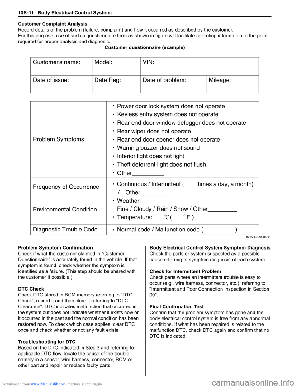
Customer Complaint Analysis
Record details of the problem (failure, complaint) and how it occurred as described by the customer.
For this purpose, use of such a questionnaire form as shown in figure will facilitate collectin g information to the point
required for proper analysis and diagnosis. Customer questionnaire (example)
Problem Symptom Confirmation
Check if what the custom er claimed in “Customer
Questionnaire” is accurately f ound in the vehicle. If that
symptom is found, check whether the symptom is
identified as a failure. (This step should be shared with
the customer if possible.)
DTC Check
Check DTC stored in BCM me mory referring to “DTC
Check”, record it and then clear it referring to “DTC
Clearance”. DTC indicates malfunction that occurred in
the system but does not indicate whether it exists now or
it occurred in the past and the normal condition has been
restored now. To check which case applies, clear DTC
once and check whether or not any fault exists.
Troubleshooting for DTC
Based on the DTC indicated in Step 3 and referring to
applicable DTC flow, locate the cause of the trouble,
namely in a sensor, wire harness, connector, BCM or
other part and repair or replace faulty parts. Body Electrical Control System Symptom Diagnosis
Check the parts or system
suspected as a possible
cause referring to symptom diagnosis of each system.
Check for Intermi ttent Problem
Check parts where an intermit tent trouble is easy to
occur (e.g., wire harness, connector, etc.), referring to
“Intermittent and Poor Connec tion Inspection in Section
00”.
Final Confirmation Test
Confirm that the problem symptom has gone and the
body electrical control system is free from any abnormal
conditions. If what has been repaired is related to the
malfunction DTC, check DTC again and confirm that no
DTC is indicated.
Customers name:
Model:
VIN:
Date of issue:
Date Reg:
Date of problem:
Mileage:
Problem Symptoms
Power door lock system does not operate
Keyless entry system does not operate
Rear end door window defogger does not operate
Rear wiper does not operate
Rear end door opener does not operate
Other
Frequency of Occurrence
Continuous / Intermittent ( times a day, a month)
/ Other
Environmental Condition
Weather:
Fine / Cloudy / Rain / Snow / Other
Temperature: (F )
Diagnostic Trouble Code Normal code / Malfunction code ( )
Warning buzzer does not sound
Interior light does not light
Theft deterrent light does not flush
I5RS0DA20006-01
Page 1422 of 1496
Downloaded from www.Manualslib.com manuals search engine 10B-19 Body Electrical Control System:
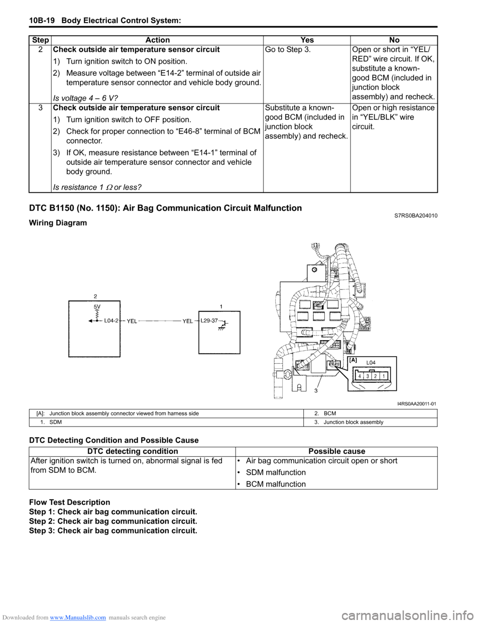
DTC B1150 (No. 1150): Air Bag Communication Circuit MalfunctionS7RS0BA204010
Wiring Diagram
DTC Detecting Condition and Possible Cause
Flow Test Description
Step 1: Check air bag communication circuit.
Step 2: Check air bag communication circuit.
Step 3: Check air bag communication circuit. 2
Check outside air temperature sensor circuit
1) Turn ignition switch to ON position.
2) Measure voltage between “E14-2” terminal of outside air
temperature sensor connector and vehicle body ground.
Is voltage 4 – 6 V? Go to Step 3. Open or short in “YEL/
RED” wire circuit. If OK,
substitute a known-
good BCM (included in
junction block
assembly) and recheck.
3 Check outside air temperature sensor circuit
1) Turn ignition switch to OFF position.
2) Check for proper connection to “E46-8” terminal of BCM
connector.
3) If OK, measure resistance between “E14-1” terminal of outside air temperature sens or connector and vehicle
body ground.
Is resistance 1
Ω or less? Substitute a known-
good BCM (included in
junction block
assembly) and recheck.
Open or high resistance
in “YEL/BLK” wire
circuit.
Step Action Yes No
I4RS0AA20011-01
[A]: Junction block assembly connect
or viewed from harness side 2. BCM
1. SDM 3. Junction block assembly
DTC detecting conditionPossible cause
After ignition switch is turned on, abnormal signal is fed
from SDM to BCM. • Air bag communication circuit open or short
• SDM malfunction
• BCM malfunction
Page 1438 of 1496
Downloaded from www.Manualslib.com manuals search engine 10B-35 Body Electrical Control System:
Junction block connector “L06”
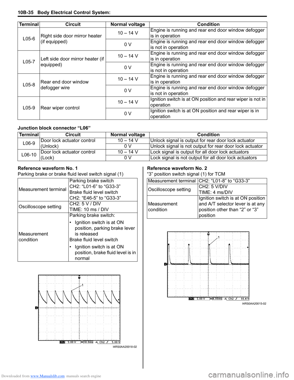
Reference waveform No. 1
Parking brake or brake fluid level switch signal (1)Reference waveform No. 2
“3” position switch signal (1) for TCM
L05-6
Right side door mirror heater
(if equipped) 10 – 14 V
Engine is running and rear end door window defogger
is in operation
0 V Engine is running and rear end door window defogger
is not in operation
L05-7 Left side door mirror heater (if
equipped) 10 – 14 V
Engine is running and rear end door window defogger
is in operation
0 V Engine is running and rear end door window defogger
is not in operation
L05-8 Rear end door window
defogger wire 10 – 14 V
Engine is running and rear end door window defogger
is in operation
0 V Engine is running and rear end door window defogger
is not in operation
L05-9 Rear wiper control 10 – 14 V
Ignition switch is at ON posi
tion and rear wiper is not in
operation
0 V Ignition switch is at ON pos
ition and rear wiper is in
operation
Terminal Circuit Normal voltage Condition
Terminal
CircuitNormal voltage Condition
L06-9 Door lock actuator control
(Unlock) 10 – 14 V Unlock signal is outpu
t for rear door lock actuator
0 V Unlock signal is not output for rear door lock actuator
L06-10 Door lock actuator control
(Lock) 10 – 14 V Lock signal is output for all door lock actuators
0 V Lock signal is not output for all door lock actuators
Measurement terminal Parking brake switch
CH2: “L01-6” to “G33-3”
Brake fluid level switch
CH2: “E46-5” to “G33-3”
Oscilloscope setting CH2: 5 V / DIV
TIME: 10 ms / DIV
Measurement
condition Parking brake switch:
• Ignition switch is at ON
position, parking brake lever
is released
Brake fluid level switch
• Ignition switch is at ON position, brake fluid level is in
normal
I4RS0AA20018-02
Measurement terminal CH2: “L01-8” to “G33-3”
Oscilloscope setting CH2: 5 V/DIV
TIME: 4 ms/DIV
Measurement
condition Ignition switch is at ON position
and A/T selector lever is at any
position other than “2” or “3”
position
I4RS0AA20015-02
Page 1444 of 1496
Downloaded from www.Manualslib.com manuals search engine 10C-1 Immobilizer Control System:
Control Systems
Immobilizer Control System
Precautions
Precautions in Diagnosing TroublesS7RS0BA300001
• Before confirming the diagnostic trouble code (DTC),
do not disconnect connector from ECM, battery cable
from battery, ground wire harness, or main fuse. Such
disconnection will erase DTC stored in ECM.
• DTC stored in ECM memory can be checked as well as cleared by using SUZUKI scan tool. Before using
SUZUKI scan tool, read its operator’s manual
carefully to know how to use it and what functions are
available.
• Be sure to read “Precautions for Electrical Circuit Service in Section 00” before inspection.
• Communication of ECM, BCM, keyless start control module (if equipped), ABS / ESP ® control module,
steering angle sensor (ESP ® model), combination
meter and TCM (A/T model) is established by CAN
(Controller Area Network). Therefore, handle CAN
communication lines with care referring to “Precaution
for CAN Communication System in Section 00”. For
CAN communication system, refer to description on
“CAN Communication System Description in Section
1A”.
Precaution in Replacing ECMS7RS0BA300002
• If ECM is replaced with new or used one without immobilizer control function , the engine will not be
started. In case of the above, check if the newly
installed ECM has immobilizer control function.
• After ECM is replaced with new one or used one, the transponder code in the transponder built in the
ignition key has to be registered with ECM. Or, the
engine cannot be started up. For the registration
procedure, refer to “Procedure after ECM
Replacement”.
Precautions in Handling Immobilizer Control
System
S7RS0BA300003
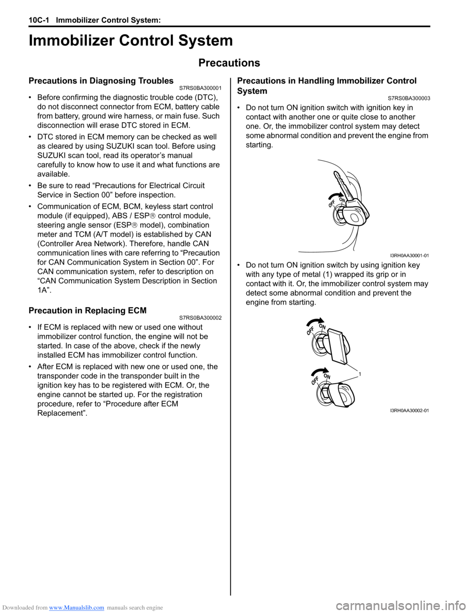
• Do not turn ON ignition sw itch with ignition key in
contact with another one or quite close to another
one. Or, the immobilizer co ntrol system may detect
some abnormal condition and prevent the engine from
starting.
• Do not turn ON ignition switch by using ignition key with any type of metal (1) wrapped its grip or in
contact with it. Or, the i mmobilizer control system may
detect some abnormal condition and prevent the
engine from starting.
I3RH0AA30001-01
1
I3RH0AA30002-01
Page 1453 of 1496
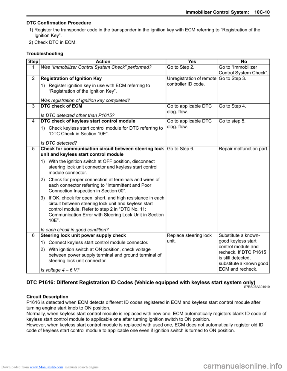
Downloaded from www.Manualslib.com manuals search engine Immobilizer Control System: 10C-10
DTC Confirmation Procedure1) Register the transponder code in the transponder in the ignition key with ECM referring to “Registration of the
Ignition Key”.
2) Check DTC in ECM.
Troubleshooting
DTC P1616: Different Registration ID Codes (Vehicle equipped with keyless start system only)S7RS0BA304010
Circuit Description
P1616 is detected when ECM detects different ID codes registered in ECM and keyless start control module after
turning engine start knob to ON position.
Normally, when keyless start control module is replaced with new one, ECM automatically registers blank ID code of
keyless start control module to applicable one after turning ignition switch to ON position.
However, when keyless start control module is replaced wit h used one, ECM does not automatically register old ID
code of keyless start control module to applicable one ev en if ignition switch is turned to ON position.
Step Action Yes No
1 Was “Immobilizer Control S ystem Check” performed? Go to Step 2. Go to “Immobilizer
Control System Check”.
2 Registration of Ignition Key
1) Register ignition key in use with ECM referring to
“Registration of the Ignition Key”.
Was registration of ignition key completed? Unregistration of remote
controller ID code.
Go to Step 3.
3 DTC check of ECM
Is DTC detected other than P1615? Go to applicable DTC
diag. flow.
Go to Step 4.
4 DTC check of keyless start control module
1) Check keyless start control module for DTC referring to
“DTC Check in Section 10E”.
Is DTC detected? Go to applicable DTC
diag. flow.
Go to step 5.
5 Check for communication circuit between steering lock
unit and keyless start control module
1) With the ignition switch at OFF position, disconnect
steering lock unit connector and keyless start control
module connector.
2) Check for proper connection at terminals and wires of
each connector referring to “Intermittent and Poor
Connection Inspection in Section 00”.
3) If OK, check for open, short, and high resistance in each circuit between steering lock unit and keyless start
control module. Refer to step 2 in “DTC No. 11:
Communication Error with Steeri ng Lock Unit in Section
10E”.
Is each circuit in good condition? Go to Step 6. Repair malfunction part.
6 Steering lock unit power supply check
1) Connect keyless start control module connector.
2) With ignition switch at ON position, check voltage
between power supply terminal and ground terminal of
steering lock unit connector.
Is voltage 4 – 6 V? Replace steering lock
unit.
Substitute a known-
good keyless start
control module and
recheck. If DTC P1615
is still detected,
substitute a known good
ECM and recheck.
Page 1457 of 1496
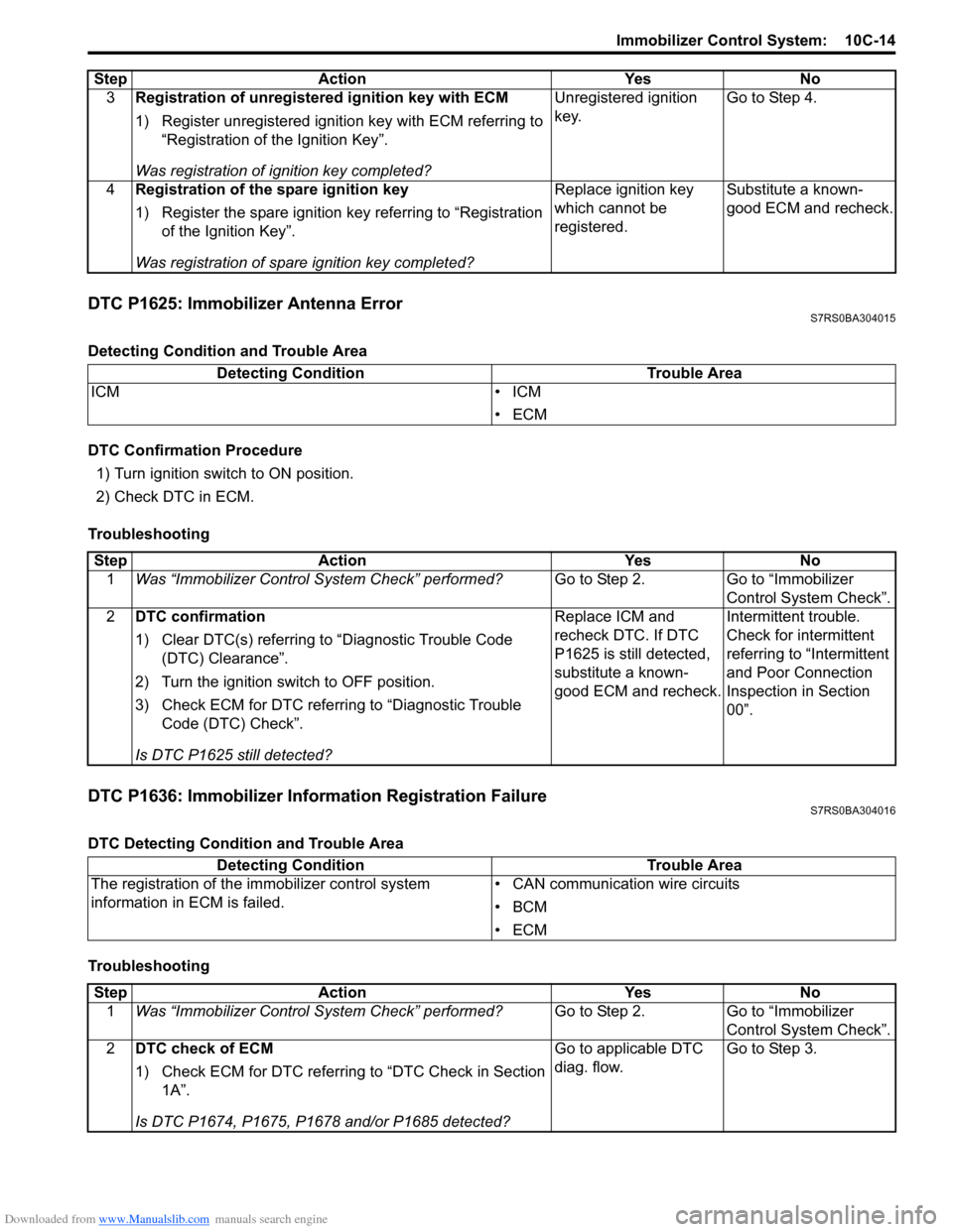
Downloaded from www.Manualslib.com manuals search engine Immobilizer Control System: 10C-14
DTC P1625: Immobilizer Antenna ErrorS7RS0BA304015
Detecting Condition and Trouble Area
DTC Confirmation Procedure1) Turn ignition switch to ON position.
2) Check DTC in ECM.
Troubleshooting
DTC P1636: Immobilizer Information Registration FailureS7RS0BA304016
DTC Detecting Condition and Trouble Area
Troubleshooting 3
Registration of unregistered ignition key with ECM
1) Register unregistered igniti on key with ECM referring to
“Registration of the Ignition Key”.
Was registration of ignition key completed? Unregistered ignition
key.
Go to Step 4.
4 Registration of the spare ignition key
1) Register the spare ignition key referring to “Registration
of the Ignition Key”.
Was registration of spare ignition key completed? Replace ignition key
which cannot be
registered.
Substitute a known-
good ECM and recheck.
Step Action Yes No
Detecting Condition
Trouble Area
ICM • ICM
•ECM
StepAction YesNo
1 Was “Immobilizer Control S ystem Check” performed? Go to Step 2.Go to “Immobilizer
Control System Check”.
2 DTC confirmation
1) Clear DTC(s) referring to “Diagnostic Trouble Code
(DTC) Clearance”.
2) Turn the ignition switch to OFF position.
3) Check ECM for DTC referring to “Diagnostic Trouble Code (DTC) Check”.
Is DTC P1625 still detected? Replace ICM and
recheck DTC. If DTC
P1625 is still detected,
substitute a known-
good ECM and recheck.
Intermittent trouble.
Check for intermittent
referring to “Intermittent
and Poor Connection
Inspection in Section
00”.
Detecting Condition
Trouble Area
The registration of the immobilizer control system
information in ECM is failed. • CAN communication wire circuits
•BCM
•ECM
Step
Action YesNo
1 Was “Immobilizer Control S ystem Check” performed? Go to Step 2.Go to “Immobilizer
Control System Check”.
2 DTC check of ECM
1) Check ECM for DTC referring to “DTC Check in Section
1A”.
Is DTC P1674, P1675, P1678 and/or P1685 detected? Go to applicable DTC
diag. flow.
Go to Step 3.
Page 1483 of 1496
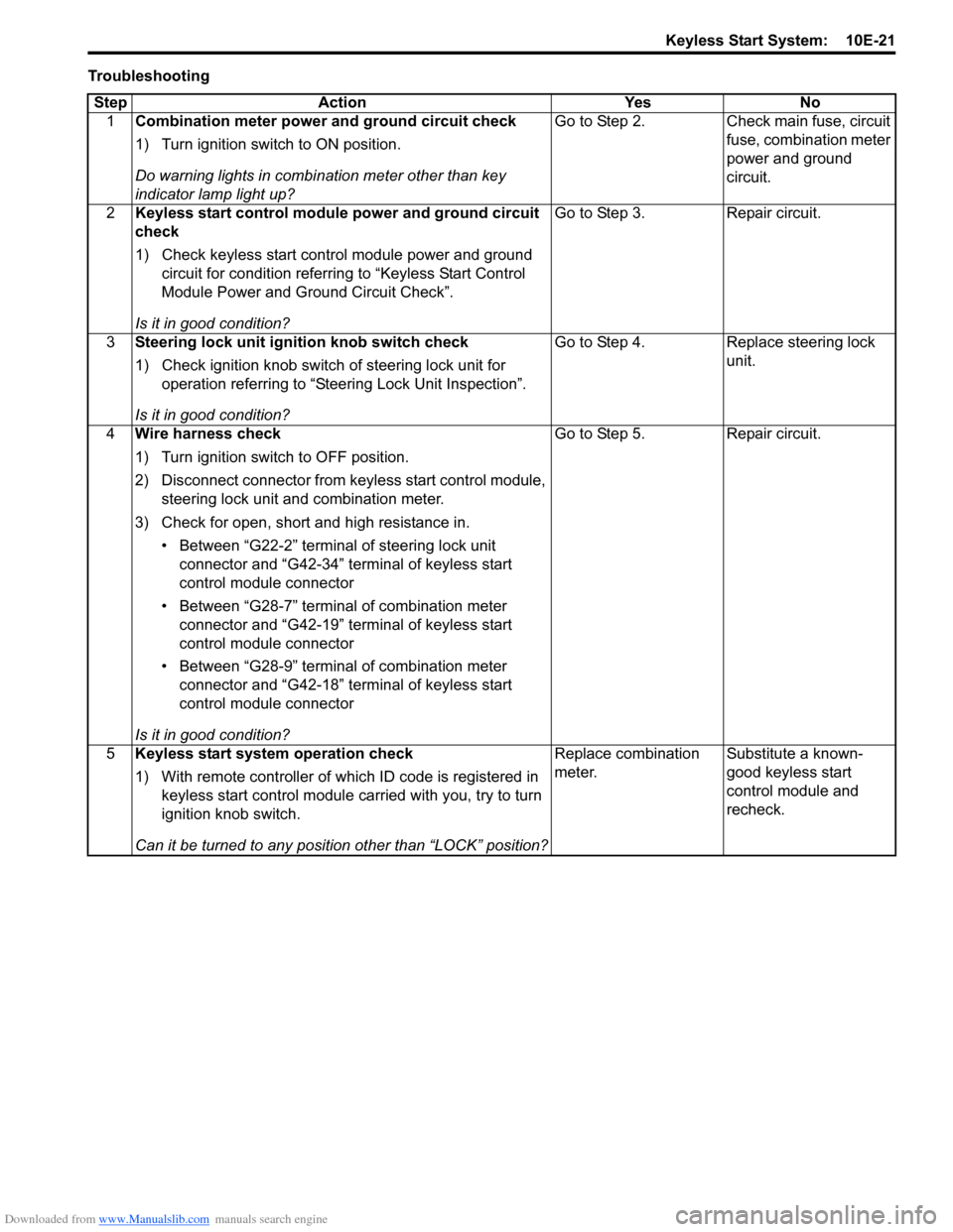
Downloaded from www.Manualslib.com manuals search engine Keyless Start System: 10E-21
TroubleshootingStep Action Yes No 1 Combination meter power and ground circuit check
1) Turn ignition switch to ON position.
Do warning lights in combi nation meter other than key
indicator lamp light up? Go to Step 2. Check main fuse, circuit
fuse, combination meter
power and ground
circuit.
2 Keyless start control module power and ground circuit
check
1) Check keyless start control module power and ground
circuit for condition referrin g to “Keyless Start Control
Module Power and Ground Circuit Check”.
Is it in good condition? Go to Step 3. Repair circuit.
3 Steering lock unit ignition knob switch check
1) Check ignition knob switch of steering lock unit for
operation referring to “Steering Lock Unit Inspection”.
Is it in good condition? Go to Step 4. Replace steering lock
unit.
4 Wire harness check
1) Turn ignition switch to OFF position.
2) Disconnect connector from ke yless start control module,
steering lock unit and combination meter.
3) Check for open, short and high resistance in. • Between “G22-2” terminal of steering lock unit connector and “G42-34” terminal of keyless start
control module connector
• Between “G28-7” terminal of combination meter connector and “G42-19” terminal of keyless start
control module connector
• Between “G28-9” terminal of combination meter connector and “G42-18” terminal of keyless start
control module connector
Is it in good condition? Go to Step 5. Repair circuit.
5 Keyless start system operation check
1) With remote controller of which ID code is registered in
keyless start control module carried with you, try to turn
ignition knob switch.
Can it be turned to any position other than “LOCK” position? Replace combination
meter.
Substitute a known-
good keyless start
control module and
recheck.
Page 1486 of 1496
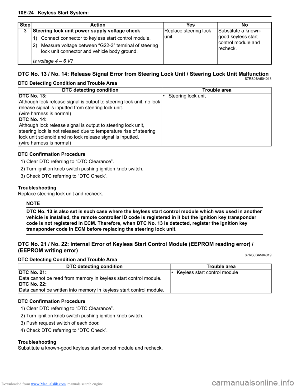
Downloaded from www.Manualslib.com manuals search engine 10E-24 Keyless Start System:
DTC No. 13 / No. 14: Release Signal Error from Steering Lock Unit / Steering Lock Unit MalfunctionS7RS0BA504018
DTC Detecting Condition and Trouble Area
DTC Confirmation Procedure1) Clear DTC referring to “DTC Clearance”.
2) Turn ignition knob switch pushing ignition knob switch.
3) Check DTC referring to “DTC Check”.
Troubleshooting
Replace steering lock unit and recheck.
NOTE
DTC No. 13 is also set is such case where the keyless start control module which was used in another
vehicle is installed, the remote controller ID code is registered in it but the ignition key transponder
code is not registered in ECM. Therefore, when DTC No. 13 is detected, register the ignition key
transponder code in ECM before replacing the steering lock unit.
DTC No. 21 / No. 22: Internal Error of Keyle ss Start Control Module (EEPROM reading error) /
(EEPROM writing error)
S7RS0BA504019
DTC Detecting Condition and Trouble Area
DTC Confirmation Procedure
1) Clear DTC referring to “DTC Clearance”.
2) Turn ignition knob switch pushing ignition knob switch.
3) Push request switch of each door.
4) Check DTC referring to “DTC Check”.
Troubleshooting
Substitute a known-good keyless start control module and recheck. 3
Steering lock unit power supply voltage check
1) Connect connector to keyl ess start control module.
2) Measure voltage between “G22-3” terminal of steering lock unit connector and vehicle body ground.
Is voltage 4 – 6 V? Replace steering lock
unit.
Substitute a known-
good keyless start
control module and
recheck.
Step Action Yes No
DTC detecting condition
Trouble area
DTC No. 13:
Although lock release signal is ou tput to steering lock unit, no lock
release signal is inputted from steering lock unit.
(wire harness is normal)
DTC No. 14:
Although lock release signal is output to steering lock unit,
steering lock is not released due to temperature rise of steering
lock unit solenoid and no lock release signal is inputted.
(wire harness is normal) • Steering lock unit
DTC detecting condition Trouble area
DTC No. 21:
Data cannot be read from memory in keyless start control module.
DTC No. 22:
Data cannot be written into memory in keyless start control module.• Keyless start control module
Page 1491 of 1496
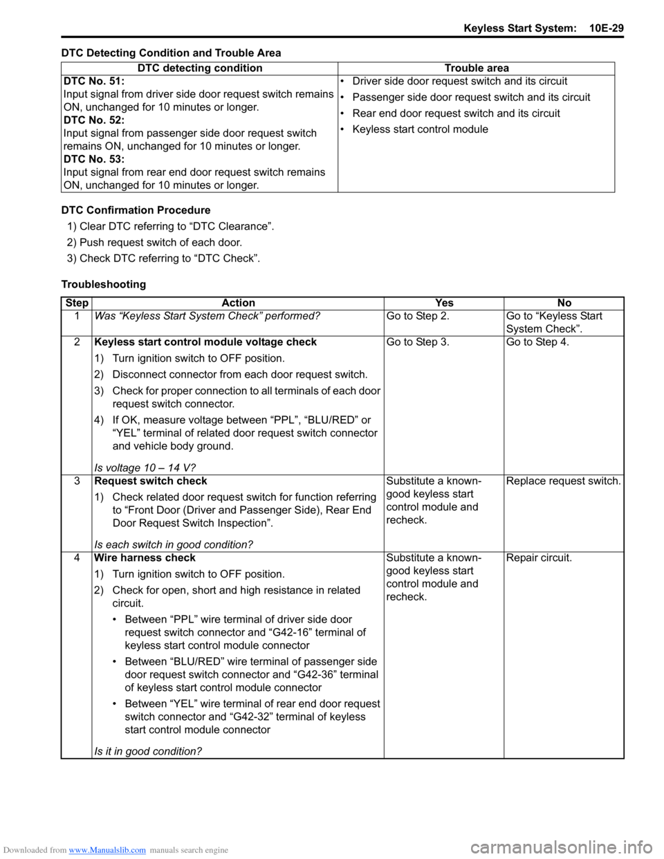
Downloaded from www.Manualslib.com manuals search engine Keyless Start System: 10E-29
DTC Detecting Condition and Trouble Area
DTC Confirmation Procedure1) Clear DTC referring to “DTC Clearance”.
2) Push request switch of each door.
3) Check DTC referring to “DTC Check”.
Troubleshooting DTC detecting condition Trouble area
DTC No. 51:
Input signal from driver side door request switch remains
ON, unchanged for 10 minutes or longer.
DTC No. 52:
Input signal from passenger side door request switch
remains ON, unchanged for 10 minutes or longer.
DTC No. 53:
Input signal from rear end door request switch remains
ON, unchanged for 10 minutes or longer. • Driver side door request switch and its circuit
• Passenger side door request switch and its circuit
• Rear end door request switch and its circuit
• Keyless start control module
Step
Action YesNo
1 Was “Keyless Start System Check” performed? Go to Step 2.Go to “Keyless Start
System Check”.
2 Keyless start control module voltage check
1) Turn ignition switch to OFF position.
2) Disconnect connector from each door request switch.
3) Check for proper connection to all terminals of each door
request switch connector.
4) If OK, measure voltage between “PPL”, “BLU/RED” or “YEL” terminal of related door request switch connector
and vehicle body ground.
Is voltage 10 – 14 V? Go to Step 3.
Go to Step 4.
3 Request switch check
1) Check related door request switch for function referring
to “Front Door (Driver and Passenger Side), Rear End
Door Request Switch Inspection”.
Is each switch in good condition? Substitute a known-
good keyless start
control module and
recheck.
Replace request switch.
4 Wire harness check
1) Turn ignition switch to OFF position.
2) Check for open, short and high resistance in related
circuit.
• Between “PPL” wire terminal of driver side door request switch connector and “G42-16” terminal of
keyless start control module connector
• Between “BLU/RED” wire terminal of passenger side door request switch connector and “G42-36” terminal
of keyless start control module connector
• Between “YEL” wire terminal of rear end door request switch connector and “G42-32” terminal of keyless
start control module connector
Is it in good condition? Substitute a known-
good keyless start
control module and
recheck.
Repair circuit.