Abs install SUZUKI SWIFT 2008 2.G Service Owner's Guide
[x] Cancel search | Manufacturer: SUZUKI, Model Year: 2008, Model line: SWIFT, Model: SUZUKI SWIFT 2008 2.GPages: 1496, PDF Size: 34.44 MB
Page 995 of 1496
Downloaded from www.Manualslib.com manuals search engine Air Conditioning System: Automatic Type 7B-47
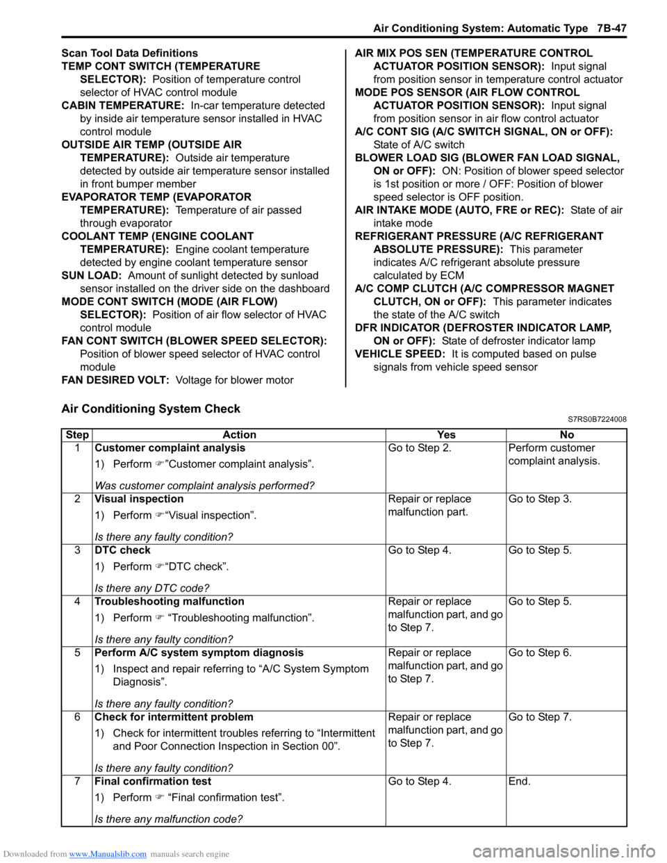
Scan Tool Data Definitions
TEMP CONT SWITCH (TEMPERATURE SELECTOR): Position of temperature control
selector of HVAC control module
CABIN TEMPERATURE: In-car temperature detected
by inside air temperature sensor installed in HVAC
control module
OUTSIDE AIR TEMP (OUTSIDE AIR TEMPERATURE): Outside air temperature
detected by outside air temperature sensor installed
in front bumper member
EVAPORATOR TEMP (EVAPORATOR TEMPERATURE): Temperature of air passed
through evaporator
COOLANT TEMP (ENGINE COOLANT TEMPERATURE): Engine coolant temperature
detected by engine coolant temperature sensor
SUN LOAD: Amount of sunlight detected by sunload
sensor installed on the driver side on the dashboard
MODE CONT SWITCH (MODE (AIR FLOW) SELECTOR): Position of air flow selector of HVAC
control module
FAN CONT SWITCH (BLOWER SPEED SELECTOR): Position of blower speed selector of HVAC control
module
FAN DESIRED VOLT: Voltage for blower motor AIR MIX POS SEN (TEMPERATURE CONTROL
ACTUATOR POSITI ON SENSOR): Input signal
from position sensor in temperature control actuator
MODE POS SENSOR (AIR FLOW CONTROL ACTUATOR POSITI ON SENSOR): Input signal
from position sensor in air flow control actuator
A/C CONT SIG (A/C SWITCH SIGNAL, ON or OFF): State of A/C switch
BLOWER LOAD SIG (BLO WER FAN LOAD SIGNAL,
ON or OFF): ON: Position of blower speed selector
is 1st position or more / OFF: Position of blower
speed selector is OFF position.
AIR INTAKE MODE (AUTO, FRE or REC): State of air
intake mode
REFRIGERANT PRESSURE (A/C REFRIGERANT ABSOLUTE PRESSURE): This parameter
indicates A/C refrigerant absolute pressure
calculated by ECM
A/C COMP CLUTCH (A/C COMPRESSOR MAGNET CLUTCH, ON or OFF): This parameter indicates
the state of the A/C switch
DFR INDICATOR (DEFROSTER INDICATOR LAMP, ON or OFF): State of defroster indicator lamp
VEHICLE SPEED: It is computed based on pulse
signals from vehicle speed sensor
Air Conditioning System CheckS7RS0B7224008
Step Action YesNo
1 Customer complaint analysis
1) Perform �)”Customer complaint analysis”.
Was customer complaint analysis performed? Go to Step 2.
Perform customer
complaint analysis.
2 Visual inspection
1) Perform �)“Visual inspection”.
Is there any faulty condition? Repair or replace
malfunction part.
Go to Step 3.
3 DTC check
1) Perform �)“DTC check”.
Is there any DTC code? Go to Step 4.
Go to Step 5.
4 Troubleshooting malfunction
1) Perform �) “Troubleshooting malfunction”.
Is there any faulty condition? Repair or replace
malfunction part, and go
to Step 7.
Go to Step 5.
5 Perform A/C system symptom diagnosis
1) Inspect and repair referri ng to “A/C System Symptom
Diagnosis”.
Is there any faulty condition? Repair or replace
malfunction part, and go
to Step 7.
Go to Step 6.
6 Check for intermittent problem
1) Check for intermittent troubles referring to “Intermittent
and Poor Connection Inspection in Section 00”.
Is there any faulty condition? Repair or replace
malfunction part, and go
to Step 7.
Go to Step 7.
7 Final confirmation test
1) Perform �) “Final confirmation test”.
Is there any malfunction code? Go to Step 4.
End.
Page 1388 of 1496
Downloaded from www.Manualslib.com manuals search engine 9L-1 Paint / Coatings:
Body, Cab and Accessories
Paint / Coatings
General Description
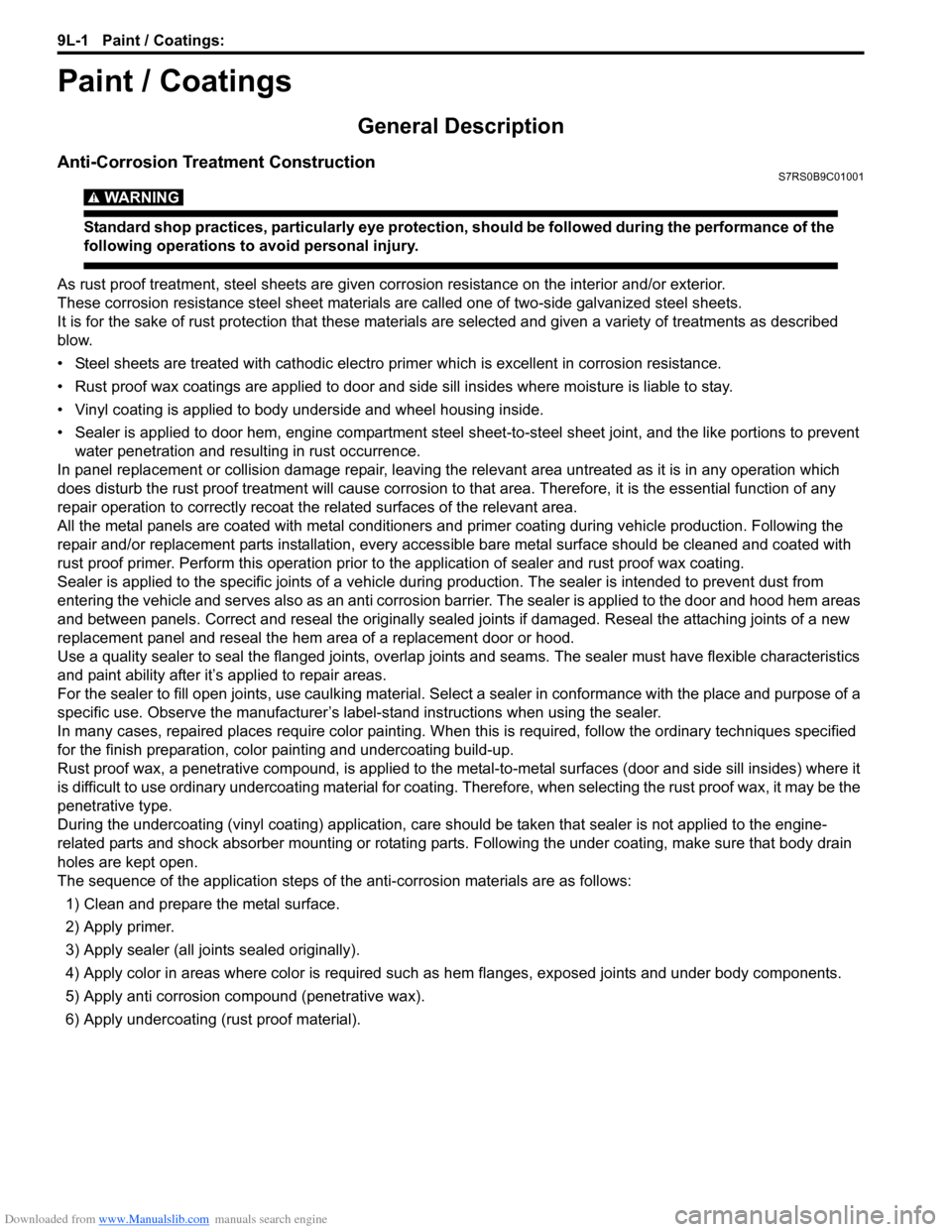
Anti-Corrosion Treatment ConstructionS7RS0B9C01001
WARNING!
Standard shop practices, particularly eye protection, should be followed during the performance of the
following operations to avoid personal injury.
As rust proof treatment, steel sheets are given corrosion resistance on the interior and/or exterior.
These corrosion resistance steel sheet materials ar e called one of two-side galvanized steel sheets.
It is for the sake of rust protection that these materials are selected and given a variety of treatments as described
blow.
• Steel sheets are treated with cathodic electro primer which is excellent in corrosion resistance.
• Rust proof wax coatings are applied to door and side sill insides where mois ture is liable to stay.
• Vinyl coating is applied to body underside and wheel housing inside.
• Sealer is applied to door hem, engine compartment steel sheet-to-steel sheet joint, and the like portions to prevent water penetration and resulting in rust occurrence.
In panel replacement or collision damage repair, leaving the relevant area untreated as it is in any operation which
does disturb the rust proof treatment will cause corrosion to th at area. Therefore, it is the essential function of any
repair operation to correctly recoat t he related surfaces of the relevant area.
All the metal panels are coated with metal conditioners an d primer coating during vehicle production. Following the
repair and/or replacement parts installation, every access ible bare metal surface should be cleaned and coated with
rust proof primer. Perform this operation prior to the application of sealer and rust proof wax coating.
Sealer is applied to the spec ific joints of a vehicle during production. The sealer is intended to prevent dust from
entering the vehicle and serves also as an anti corrosion barrier. The sealer is applied to the door and hood hem areas
and between panels. Correct and reseal the originally sealed joints if damaged. Reseal the attaching joints of a new
replacement panel and reseal the hem area of a replacement door or hood.
Use a quality sealer to seal the flanged joints, overlap joints and seams. The sealer must have flexible characteristics
and paint ability after it’s applied to repair areas.
For the sealer to fill open joints, use caulking material. Select a sealer in conf ormance with the place and purpose of a
specific use. Observe the ma nufacturer’s label-stand instructions when using the sealer.
In many cases, repaired places require color painting. When this is required, follow the ordinary techniques specified
for the finish preparation, color painting and undercoating build-up.
Rust proof wax, a penetrative compound, is applied to the metal-to-metal surfaces (door and side sill insides) where it
is difficult to use ordinary undercoating material for coating. Therefore, when selecting the rust proof wax, it may be the
penetrative type.
During the undercoating (vinyl coating) application, care should be taken that sealer is not applied to the engine-
related parts and shock absorber mounting or rotating parts. Following the under coating, make sure that body drain
holes are kept open.
The sequence of the application steps of the anti-corrosion materials are as follows:
1) Clean and prepare the metal surface.
2) Apply primer.
3) Apply sealer (all joints sealed originally).
4) Apply color in areas where color is required such as hem flanges, exposed joints and under body components.
5) Apply anti corrosion compound (penetrative wax).
6) Apply undercoating (rust proof material).
Page 1444 of 1496
Downloaded from www.Manualslib.com manuals search engine 10C-1 Immobilizer Control System:
Control Systems
Immobilizer Control System
Precautions
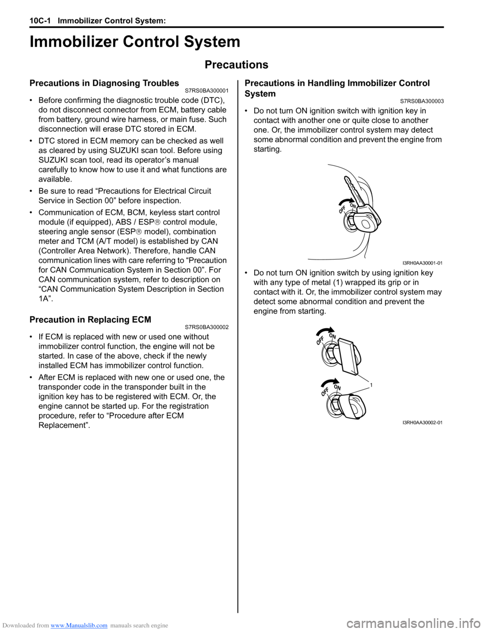
Precautions in Diagnosing TroublesS7RS0BA300001
• Before confirming the diagnostic trouble code (DTC),
do not disconnect connector from ECM, battery cable
from battery, ground wire harness, or main fuse. Such
disconnection will erase DTC stored in ECM.
• DTC stored in ECM memory can be checked as well as cleared by using SUZUKI scan tool. Before using
SUZUKI scan tool, read its operator’s manual
carefully to know how to use it and what functions are
available.
• Be sure to read “Precautions for Electrical Circuit Service in Section 00” before inspection.
• Communication of ECM, BCM, keyless start control module (if equipped), ABS / ESP ® control module,
steering angle sensor (ESP ® model), combination
meter and TCM (A/T model) is established by CAN
(Controller Area Network). Therefore, handle CAN
communication lines with care referring to “Precaution
for CAN Communication System in Section 00”. For
CAN communication system, refer to description on
“CAN Communication System Description in Section
1A”.
Precaution in Replacing ECMS7RS0BA300002
• If ECM is replaced with new or used one without immobilizer control function , the engine will not be
started. In case of the above, check if the newly
installed ECM has immobilizer control function.
• After ECM is replaced with new one or used one, the transponder code in the transponder built in the
ignition key has to be registered with ECM. Or, the
engine cannot be started up. For the registration
procedure, refer to “Procedure after ECM
Replacement”.
Precautions in Handling Immobilizer Control
System
S7RS0BA300003
• Do not turn ON ignition sw itch with ignition key in
contact with another one or quite close to another
one. Or, the immobilizer co ntrol system may detect
some abnormal condition and prevent the engine from
starting.
• Do not turn ON ignition switch by using ignition key with any type of metal (1) wrapped its grip or in
contact with it. Or, the i mmobilizer control system may
detect some abnormal condition and prevent the
engine from starting.
I3RH0AA30001-01
1
I3RH0AA30002-01
Page 1451 of 1496
Downloaded from www.Manualslib.com manuals search engine Immobilizer Control System: 10C-8
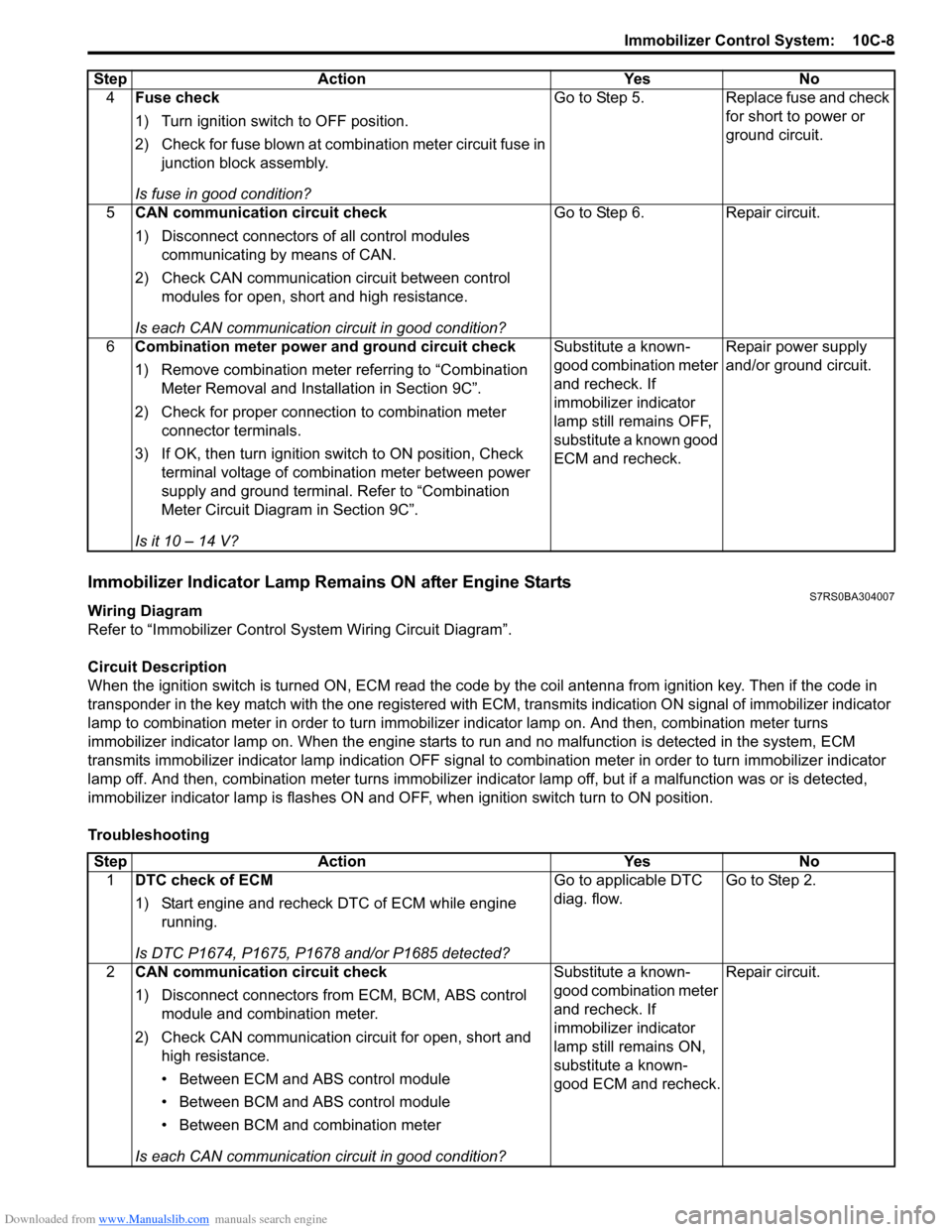
Immobilizer Indicator Lamp Remains ON after Engine StartsS7RS0BA304007
Wiring Diagram
Refer to “Immobilizer Control S ystem Wiring Circuit Diagram”.
Circuit Description
When the ignition switch is turned ON, ECM read the code by the coil antenna from ignition key. Then if the code in
transponder in the key match with the one registered with ECM, transmits indication ON signal of immobilizer indicator
lamp to combination meter in order to turn immobilizer indicator lamp on. And then, combination meter turns
immobilizer indicator lamp on. When th e engine starts to run and no malfunction is detected in the system, ECM
transmits immobilizer indicator lamp indication O FF signal to combination meter in order to turn immobilizer indicator
lamp off. And then, comb ination meter turns immobilizer indicator lamp off, but if a malfunction was or is detected,
immobilizer indicator lamp is flashes ON and OF F, when ignition switch turn to ON position.
Troubleshooting 4
Fuse check
1) Turn ignition switch to OFF position.
2) Check for fuse blown at combination meter circuit fuse in
junction block assembly.
Is fuse in good condition? Go to Step 5. Replace fuse and check
for short to power or
ground circuit.
5 CAN communication circuit check
1) Disconnect connectors of all control modules
communicating by means of CAN.
2) Check CAN communication circuit between control modules for open, short and high resistance.
Is each CAN communication circuit in good condition? Go to Step 6. Repair circuit.
6 Combination meter power and ground circuit check
1) Remove combination meter referring to “Combination
Meter Removal and Installation in Section 9C”.
2) Check for proper connection to combination meter connector terminals.
3) If OK, then turn ignition switch to ON position, Check terminal voltage of combination meter between power
supply and ground terminal. Refer to “Combination
Meter Circuit Diagram in Section 9C”.
Is it 10 – 14 V? Substitute a known-
good combination meter
and recheck. If
immobilizer indicator
lamp still remains OFF,
substitute a known good
ECM and recheck.
Repair power supply
and/or ground circuit.
Step Action Yes No
Step
Action YesNo
1 DTC check of ECM
1) Start engine and recheck DTC of ECM while engine
running.
Is DTC P1674, P1675, P1678 and/or P1685 detected? Go to applicable DTC
diag. flow.
Go to Step 2.
2 CAN communication circuit check
1) Disconnect connectors from ECM, BCM, ABS control
module and combination meter.
2) Check CAN communication circuit for open, short and high resistance.
• Between ECM and ABS control module
• Between BCM and ABS control module
• Between BCM and combination meter
Is each CAN communication circuit in good condition? Substitute a known-
good combination meter
and recheck. If
immobilizer indicator
lamp still remains ON,
substitute a known-
good ECM and recheck.
Repair circuit.
Page 1458 of 1496
Downloaded from www.Manualslib.com manuals search engine 10C-15 Immobilizer Control System:
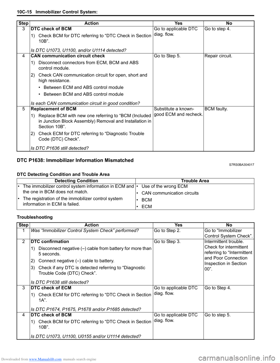
DTC P1638: Immobilizer Information MismatchedS7RS0BA304017
DTC Detecting Condition and Trouble Area
Troubleshooting3
DTC check of BCM
1) Check BCM for DTC referring to “DTC Check in Section
10B”.
Is DTC U1073, U1100, and/or U1114 detected? Go to applicable DTC
diag. flow.
Go to step 4.
4 CAN communication circuit check
1) Disconnect connectors from ECM, BCM and ABS
control module.
2) Check CAN communication circuit for open, short and high resistance.
• Between ECM and ABS control module
• Between BCM and ABS control module
Is each CAN communication circuit in good condition? Go to Step 5. Repair circuit.
5 Replacement of BCM
1) Replace BCM with new one referring to “BCM (Included
in Junction Block Assembly) Removal and Installation in
Section 10B”.
2) Check ECM for DTC referring to “Diagnostic Trouble Code (DTC) Check”.
Is DTC P1636 still detected? Substitute a known-
good ECM and recheck.
BCM faulty.
Step Action Yes No
Detecting Condition
Trouble Area
• The immobilizer control sys tem information in ECM and
the one in BCM does not match.
• The registration of the immobilizer control system
information in ECM is failed. • Use of the wrong ECM
• CAN communication circuits
•BCM
•ECM
Step
Action YesNo
1 Was “Immobilizer Control S ystem Check” performed? Go to Step 2.Go to “Immobilizer
Control System Check”.
2 DTC confirmation
1) Disconnect negative (–) cable from battery for more than
5 seconds.
2) Connect negative (–) cable to battery.
3) Check if any DTC is detecte d referring to “Diagnostic
Trouble Code (DTC) Check”.
Is DTC P1638 still detected? Go to Step 3.
Intermittent trouble.
Check for intermittent
referring to “Intermittent
and Poor Connection
Inspection in Section
00”.
3 DTC check of ECM
1) Check ECM for DTC referring to “DTC Check in Section
1A”.
Is DTC P1674, P1675, P1678 and/or P1685 detected? Go to applicable DTC
diag. flow.
Go to Step 4.
4 DTC check of BCM
1) Check BCM for DTC referring to “DTC Check in Section
10B”.
Is DTC U1073, U1100, U0155 and/or U1114 detected? Go to applicable DTC
diag. flow.
Go to step 5.
Page 1459 of 1496
Downloaded from www.Manualslib.com manuals search engine Immobilizer Control System: 10C-16
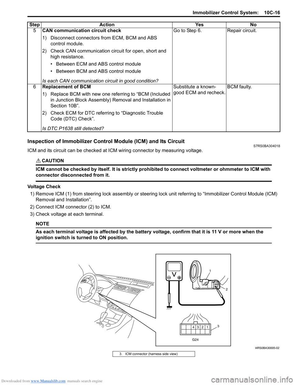
Inspection of Immobilizer Control Module (ICM) and Its CircuitS7RS0BA304018
ICM and its circuit can be checked at ICM wiring connector by measuring voltage.
CAUTION!
ICM cannot be checked by itself. It is strictly prohibited to connect voltmeter or ohmmeter to ICM with
connector disconnected from it.
Voltage Check
1) Remove ICM (1) from steering lock assembly or steering lock unit referrin g to “Immobilizer Control Module (ICM)
Removal and Installation”.
2) Connect ICM connector (2) to ICM.
3) Check voltage at each terminal.
NOTE
As each terminal voltage is affected by the battery voltage, confirm that it is 11 V or more when the
ignition switch is turned to ON position.
5 CAN communication circuit check
1) Disconnect connectors from ECM, BCM and ABS
control module.
2) Check CAN communication circuit for open, short and high resistance.
• Between ECM and ABS control module
• Between BCM and ABS control module
Is each CAN communication circuit in good condition? Go to Step 6. Repair circuit.
6 Replacement of BCM
1) Replace BCM with new one referring to “BCM (Included
in Junction Block Assembly) Removal and Installation in
Section 10B”.
2) Check ECM for DTC referring to “Diagnostic Trouble Code (DTC) Check”.
Is DTC P1638 still detected? Substitute a known-
good ECM and recheck.
BCM faulty.
Step Action Yes No
12
3
4
G24
1
2
3
I4RS0BA30005-02
3. ICM connector (harness side view)
Page 1470 of 1496
Downloaded from www.Manualslib.com manuals search engine 10E-8 Keyless Start System:
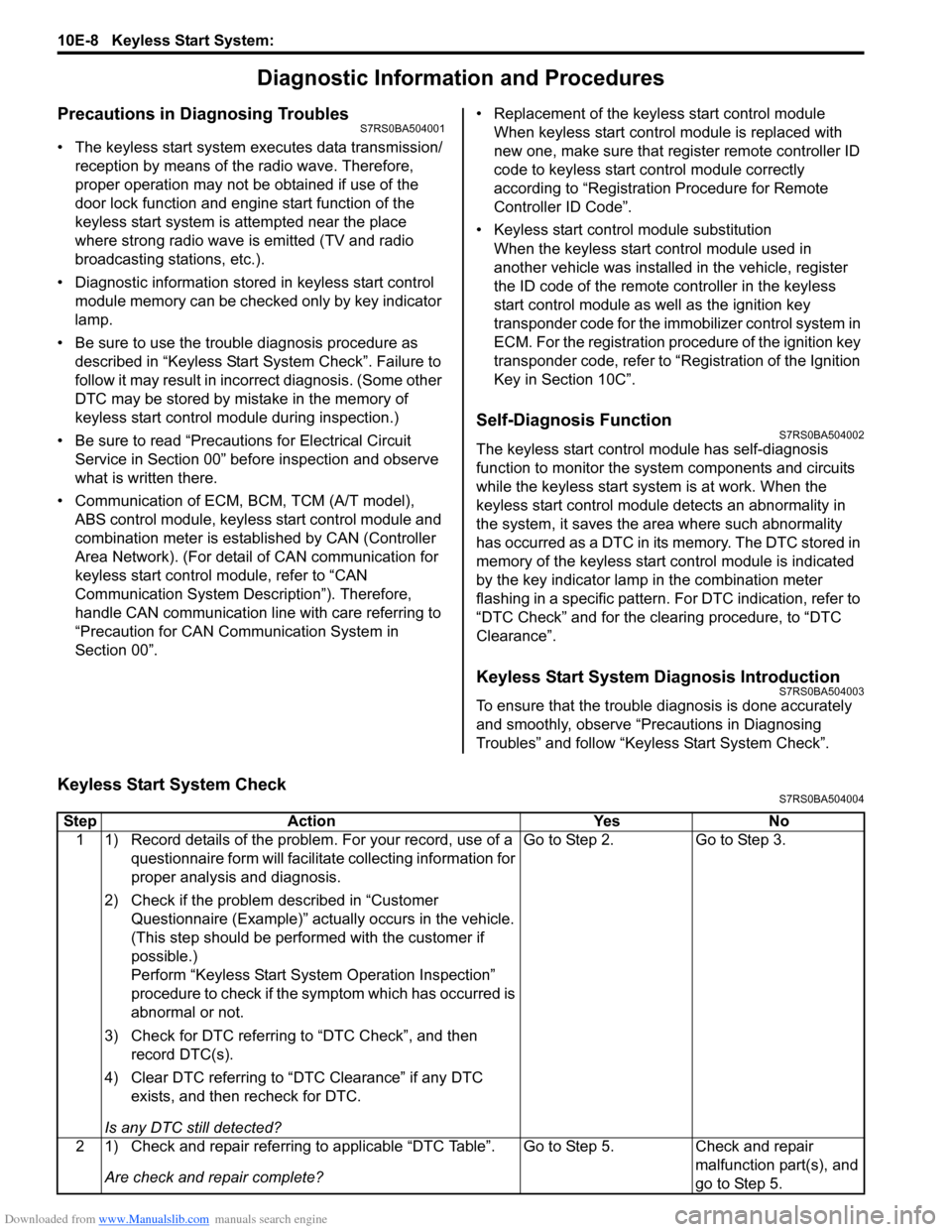
Diagnostic Information and Procedures
Precautions in Diagnosing TroublesS7RS0BA504001
• The keyless start system executes data transmission/reception by means of th e radio wave. Therefore,
proper operation may not be obtained if use of the
door lock function and engine start function of the
keyless start system is attempted near the place
where strong radio wave is emitted (TV and radio
broadcasting stations, etc.).
• Diagnostic information stored in keyless start control
module memory can be checked only by key indicator
lamp.
• Be sure to use the trouble diagnosis procedure as described in “Keyless Start System Check”. Failure to
follow it may result in incorrect diagnosis. (Some other
DTC may be stored by mistake in the memory of
keyless start control module during inspection.)
• Be sure to read “Precautions for Electrical Circuit Service in Section 00” befo re inspection and observe
what is written there.
• Communication of ECM, BCM, TCM (A/T model), ABS control module, keyless start control module and
combination meter is estab lished by CAN (Controller
Area Network). (For detail of CAN communication for
keyless start control module, refer to “CAN
Communication System Description”). Therefore,
handle CAN communication line with care referring to
“Precaution for CAN Communication System in
Section 00”. • Replacement of the keyless start control module
When keyless start control module is replaced with
new one, make sure that r egister remote controller ID
code to keyless start co ntrol module correctly
according to “Registration Procedure for Remote
Controller ID Code”.
• Keyless start control module substitution When the keyless start control module used in
another vehicle was installed in the vehicle, register
the ID code of the remote controller in the keyless
start control module as well as the ignition key
transponder code fo r the immobilizer control system in
ECM. For the registration procedure of the ignition key
transponder code, refer to “Registration of the Ignition
Key in Section 10C”.
Self-Diagnosis FunctionS7RS0BA504002
The keyless start control module has self-diagnosis
function to monitor the system components and circuits
while the keyless start system is at work. When the
keyless start control module detects an abnormality in
the system, it saves the ar ea where such abnormality
has occurred as a DTC in its memory. The DTC stored in
memory of the keyless start control module is indicated
by the key indicator lamp in the combination meter
flashing in a specific pattern. For DTC indication, refer to
“DTC Check” and for the clearing procedure, to “DTC
Clearance”.
Keyless Start System Diagnosis IntroductionS7RS0BA504003
To ensure that the trouble diagnosis is done accurately
and smoothly, observe “Precautions in Diagnosing
Troubles” and follow “Keyless Start System Check”.
Keyless Start System CheckS7RS0BA504004
Step Action YesNo
1 1) Record details of the problem. For your record, use of a questionnaire form will facilit ate collecting information for
proper analysis and diagnosis.
2) Check if the problem described in “Customer Questionnaire (Example)” actually occurs in the vehicle.
(This step should be performed with the customer if
possible.)
Perform “Keyless Start System Operation Inspection”
procedure to check if the symptom which has occurred is
abnormal or not.
3) Check for DTC referring to “DTC Check”, and then record DTC(s).
4) Clear DTC referring to “DTC Clearance” if any DTC exists, and then recheck for DTC.
Is any DTC still detected? Go to Step 2.
Go to Step 3.
2 1) Check and repair referring to applicable “DTC Table”. Are check and repair complete? Go to Step 5.
Check and repair
malfunction part(s), and
go to Step 5.