Washer SUZUKI SWIFT 2008 2.G Service Owner's Guide
[x] Cancel search | Manufacturer: SUZUKI, Model Year: 2008, Model line: SWIFT, Model: SUZUKI SWIFT 2008 2.GPages: 1496, PDF Size: 34.44 MB
Page 826 of 1496
Downloaded from www.Manualslib.com manuals search engine 5B-12 Manual Transmission/Transaxle:
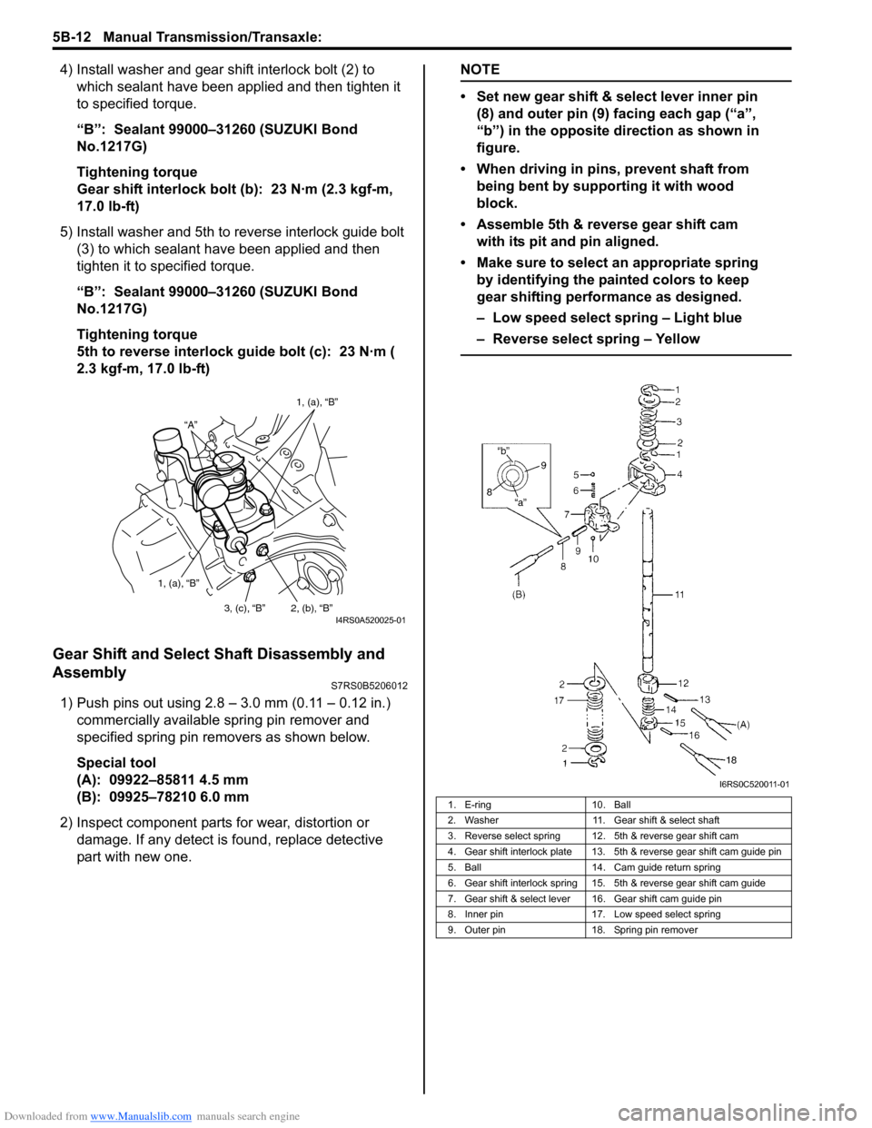
4) Install washer and gear shift interlock bolt (2) to which sealant have been app lied and then tighten it
to specified torque.
“B”: Sealant 99000–31260 (SUZUKI Bond
No.1217G)
Tightening torque
Gear shift interlock bolt (b): 23 N·m (2.3 kgf-m,
17.0 lb-ft)
5) Install washer and 5th to reverse interlock guide bolt (3) to which sealant have been applied and then
tighten it to specified torque.
“B”: Sealant 99000–31260 (SUZUKI Bond
No.1217G)
Tightening torque
5th to reverse interlock guide bolt (c): 23 N·m (
2.3 kgf-m, 17.0 lb-ft)
Gear Shift and Select Shaft Disassembly and
Assembly
S7RS0B5206012
1) Push pins out using 2.8 – 3.0 mm (0.11 – 0.12 in.) commercially available spring pin remover and
specified spring pin removers as shown below.
Special tool
(A): 09922–85811 4.5 mm
(B): 09925–78210 6.0 mm
2) Inspect component parts for wear, distortion or
damage. If any detect is found, replace detective
part with new one.
NOTE
• Set new gear shift & select lever inner pin (8) and outer pin (9) facing each gap (“a”,
“b”) in the opposite direction as shown in
figure.
• When driving in pins, prevent shaft from being bent by supporting it with wood
block.
• Assemble 5th & reverse gear shift cam with its pit and pin aligned.
• Make sure to select an appropriate spring by identifying the painted colors to keep
gear shifting performance as designed.
– Low speed select spring – Light blue
– Reverse select spring – Yellow
“A” 1, (a), “B”
1, (a), “B” 2, (b), “B”
3, (c), “B”
I4RS0A520025-01
1. E-ring 10. Ball
2. Washer 11. Gear shift & select shaft
3. Reverse select spring 12. 5th & reverse gear shift cam
4. Gear shift interlock plate 13. 5th & reverse gear shift cam guide pin
5. Ball 14. Cam guide return spring
6. Gear shift interlock spring 15. 5th & reverse gear shift cam guide
7. Gear shift & select lever 16. Gear shift cam guide pin
8. Inner pin 17. Low speed select spring
9. Outer pin 18. Spring pin remover
I6RS0C520011-01
Page 827 of 1496
Downloaded from www.Manualslib.com manuals search engine Manual Transmission/Transaxle: 5B-13
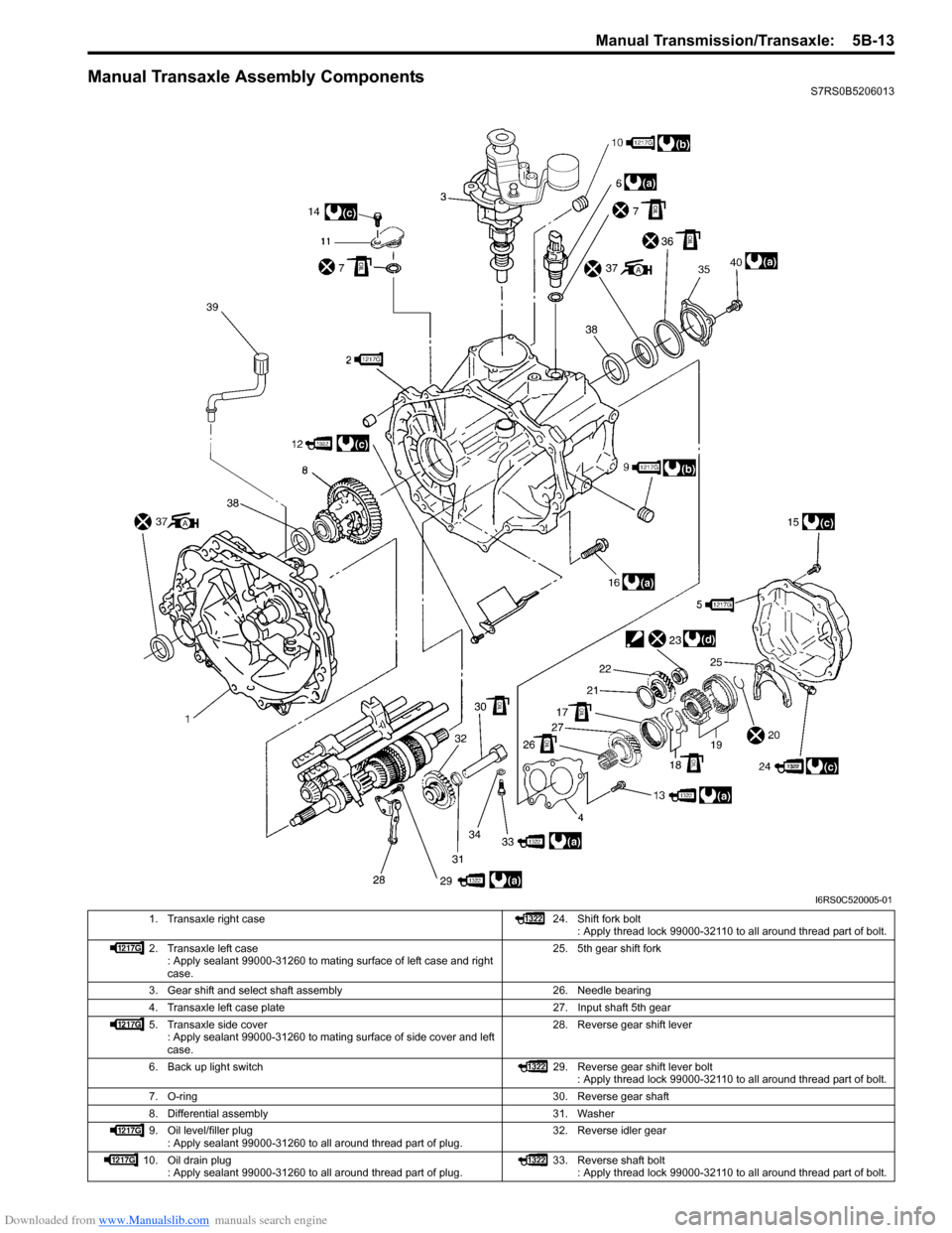
Manual Transaxle Assembly ComponentsS7RS0B5206013
I6RS0C520005-01
1. Transaxle right case 24. Shift fork bolt
: Apply thread lock 99000-32110 to all around thread part of bolt.
2. Transaxle left case : Apply sealant 99000-31260 to mating surface of left case and right
case. 25. 5th gear shift fork
3. Gear shift and select shaft assembly 26. Needle bearing
4. Transaxle left case plate 27. Input shaft 5th gear
5. Transaxle side cover : Apply sealant 99000-31260 to mating surface of side cover and left
case. 28. Reverse gear shift lever
6. Back up light switch 29. Reverse gear shift lever bolt
: Apply thread lock 99000-32110 to all around thread part of bolt.
7. O-ring 30. Reverse gear shaft
8. Differential assembly 31. Washer
9. Oil level/filler plug : Apply sealant 99000-31260 to all around thread part of plug. 32. Reverse idler gear
10. Oil drain plug : Apply sealant 99000-31260 to all around thread part of plug. 33. Reverse shaft bolt
: Apply thread lock 99000-32110 to all around thread part of bolt.
Page 828 of 1496
Downloaded from www.Manualslib.com manuals search engine 5B-14 Manual Transmission/Transaxle:
Fifth Gear Disassembly and AssemblyS7RS0B5206014
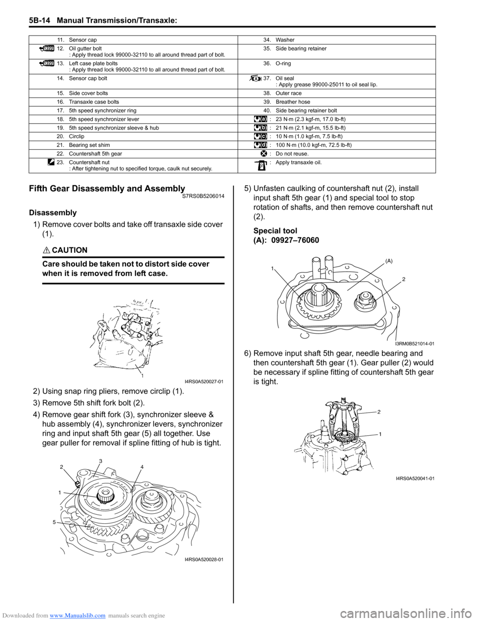
Disassembly1) Remove cover bolts and take off transaxle side cover (1).
CAUTION!
Care should be taken not to distort side cover
when it is removed from left case.
2) Using snap ring pliers, remove circlip (1).
3) Remove 5th shift fork bolt (2).
4) Remove gear shift fork (3), synchronizer sleeve &
hub assembly (4), synchron izer levers, synchronizer
ring and input shaft 5th gear (5) all together. Use
gear puller for removal if spline fitting of hub is tight. 5) Unfasten caulking of countershaft nut (2), install
input shaft 5th gear (1) and special tool to stop
rotation of shafts, and then remove countershaft nut
(2).
Special tool
(A): 09927–76060
6) Remove input shaft 5th gear, needle bearing and then countershaft 5th gear (1). Gear puller (2) would
be necessary if spline fitting of countershaft 5th gear
is tight.
11. Sensor cap 34. Washer
12. Oil gutter bolt : Apply thread lock 99000-32110 to all around thread part of bolt. 35. Side bearing retainer
13. Left case plate bolts : Apply thread lock 99000-32110 to all around thread part of bolt. 36. O-ring
14. Sensor cap bolt 37. Oil seal
: Apply grease 99000-25011 to oil seal lip.
15. Side cover bolts 38. Outer race
16. Transaxle case bolts 39. Breather hose
17. 5th speed synchronizer ring 40. Side bearing retainer bolt
18. 5th speed synchronizer lever : 23 N⋅m (2.3 kgf-m, 17.0 lb-ft)
19. 5th speed synchronizer sleeve & hub : 21 N⋅m (2.1 kgf-m, 15.5 lb-ft)
20. Circlip :10 N⋅m (1.0 kgf-m, 7.5 lb-ft)
21. Bearing set shim : 100 N⋅m (10.0 kgf-m, 72.5 lb-ft)
22. Countershaft 5th gear : Do not reuse.
23. Countershaft nut : After tightening nut to specified torque, caulk nut securely. : Apply transaxle oil.
I4RS0A520027-01
342
1
5
I4RS0A520028-01
1(A)
2
I3RM0B521014-01
I4RS0A520041-01
Page 831 of 1496
Downloaded from www.Manualslib.com manuals search engine Manual Transmission/Transaxle: 5B-17
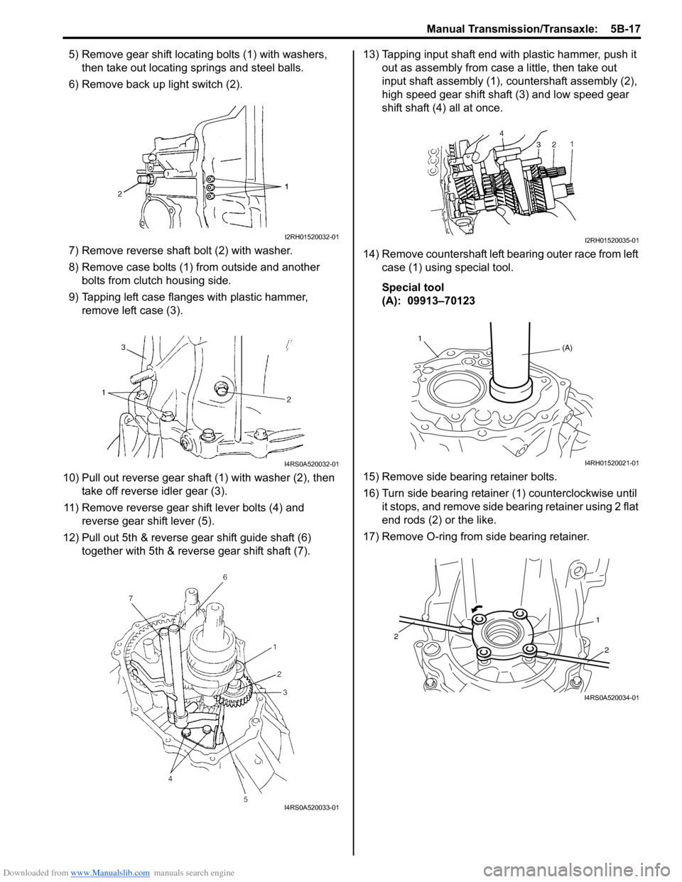
5) Remove gear shift locating bolts (1) with washers,
then take out locating springs and steel balls.
6) Remove back up light switch (2).
7) Remove reverse shaft bolt (2) with washer.
8) Remove case bolts (1) from outside and another bolts from clutch housing side.
9) Tapping left case flanges with plastic hammer, remove left case (3).
10) Pull out reverse gear shaft (1) with washer (2), then take off reverse idler gear (3).
11) Remove reverse gear shift lever bolts (4) and reverse gear shift lever (5).
12) Pull out 5th & reverse gear shift guide shaft (6) together with 5th & reverse gear shift shaft (7). 13) Tapping input shaft end with plastic hammer, push it
out as assembly from case a little, then take out
input shaft assembly (1), countershaft assembly (2),
high speed gear shift shaft (3) and low speed gear
shift shaft (4) all at once.
14) Remove countershaft left bearing outer race from left case (1) using special tool.
Special tool
(A): 09913–70123
15) Remove side bearing retainer bolts.
16) Turn side bearing retainer (1) counterclockwise until it stops, and remove side bearing retainer using 2 flat
end rods (2) or the like.
17) Remove O-ring from side bearing retainer.
I2RH01520032-01
I4RS0A520032-01
I4RS0A520033-01
I2RH01520035-01
(A)
1
I4RH01520021-01
1
2
2
I4RS0A520034-01
Page 833 of 1496
Downloaded from www.Manualslib.com manuals search engine Manual Transmission/Transaxle: 5B-19
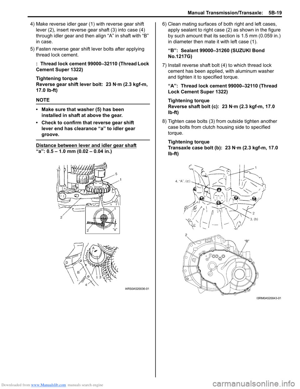
4) Make reverse idler gear (1) with reverse gear shift lever (2), insert reverse gear shaft (3) into case (4)
through idler gear and then align “A” in shaft with “B”
in case.
5) Fasten reverse gear shift lever bolts after applying thread lock cement.
: Thread lock cement 99000–32110 (Thread Lock
Cement Super 1322)
Tightening torque
Reverse gear shift lever bolt: 23 N·m (2.3 kgf-m,
17.0 lb-ft)
NOTE
• Make sure that washer (5) has been installed in shaft at above the gear.
• Check to confirm that reverse gear shift lever end has clearance “a” to idler gear
groove.
Distance between lever and idler gear shaft
“a”: 0.5 – 1.0 mm (0.02 – 0.04 in.) 6) Clean mating surfaces of both right and left cases,
apply sealant to right case (2) as shown in the figure
by such amount that its section is 1.5 mm (0.059 in.)
in diameter then mate it with left case (1).
“B”: Sealant 99000–31260 (SUZUKI Bond
No.1217G)
7) Install reverse shaft bolt (4) to which thread lock cement has been applied, with aluminum washer
and tighten it to specified torque.
“A”: Thread lock cement 99000–32110 (Thread
Lock Cement Super 1322)
Tightening torque
Reverse shaft bolt (c): 23 N·m (2.3 kgf-m, 17.0
lb-ft)
8) Tighten case bolts (3) from outside tighten another case bolts from clutch housing side to specified
torque.
Tightening torque
Transaxle case bolt (b): 23 N·m (2.3 kgf-m, 17.0
lb-ft)
I4RS0A520036-01
I3RM0A520043-01
Page 847 of 1496
Downloaded from www.Manualslib.com manuals search engine Manual Transmission/Transaxle: 5B-33
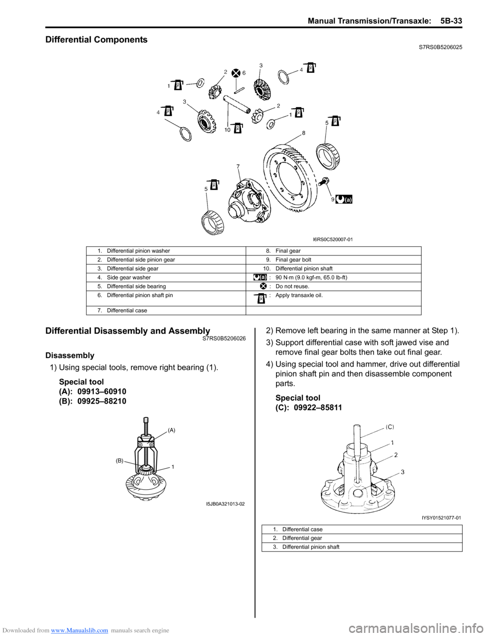
Differential ComponentsS7RS0B5206025
Differential Disassembly and AssemblyS7RS0B5206026
Disassembly1) Using special tools, remove right bearing (1).
Special tool
(A): 09913–60910
(B): 09925–88210 2) Remove left bearing in the same manner at Step 1).
3) Support differential case with soft jawed vise and
remove final gear bolts then take out final gear.
4) Using special tool and hammer, drive out differential pinion shaft pin and then disassemble component
parts.
Special tool
(C): 09922–85811
1. Differential pinion washer 8. Final gear
2. Differential side pinion gear 9. Final gear bolt
3. Differential side gear 10. Differential pinion shaft
4. Side gear washer : 90 N⋅m (9.0 kgf-m, 65.0 lb-ft)
5. Differential side bearing : Do not reuse.
6. Differential pinion shaft pin : Apply transaxle oil.
7. Differential case
I6RS0C520007-01
1(B)
(A)
I5JB0A321013-02
1. Differential case
2. Differential gear
3. Differential pinion shaft
IYSY01521077-01
Page 848 of 1496
Downloaded from www.Manualslib.com manuals search engine 5B-34 Manual Transmission/Transaxle:
Assembly
Judging from abnormality noted before disassembly and
what is found through visual check of component parts
after disassembly, prepare replacing parts and proceed
to reassembly. Make sure that all parts are clean.
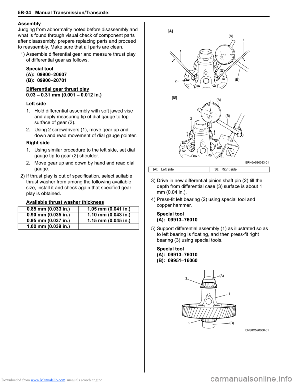
1) Assemble differential gear and measure thrust play
of differential gear as follows.
Special tool
(A): 09900–20607
(B): 09900–20701
Differential gear thrust play
0.03 – 0.31 mm (0.001 – 0.012 in.)
Left side
1. Hold differential assembly with soft jawed vise and apply measuring tip of dial gauge to top
surface of gear (2).
2. Using 2 screwdrivers (1), move gear up and down and read movement of dial gauge pointer.
Right side
1. Using similar procedure to the left side, set dial gauge tip to gear (2) shoulder.
2. Move gear up and down by hand and read dial gauge.
2) If thrust play is out of sp ecification, select suitable
thrust washer from among the following available
size, install it and check again that specified gear
play is obtained.
Available thrust washer thickness
3) Drive in new differential pinion shaft pin (2) till the depth from differential case (3) surface is about 1
mm (0.04 in.).
4) Press-fit left bearing (2) using special tool and copper hammer.
Special tool
(A): 09913–76010
5) Support differential assembly (1) as illustrated so as to left bearing is floating , and then press-fit right
bearing (3) using special tools.
Special tool
(A): 09913–76010
(B): 09951–16060
0.85 mm (0.033 in.) 1.05 mm (0.041 in.)
0.90 mm (0.035 in.) 1.10 mm (0.043 in.)
0.95 mm (0.037 in.) 1.15 mm (0.045 in.)
1.00 mm (0.039 in.)
[A]: Left side
[B]: Right side
I3RH0A520083-01
1
(A)
3
2 (B)
I6RS0C520008-01
Page 922 of 1496
Downloaded from www.Manualslib.com manuals search engine 6C-40 Power Assisted Steering System:
Repair Instructions
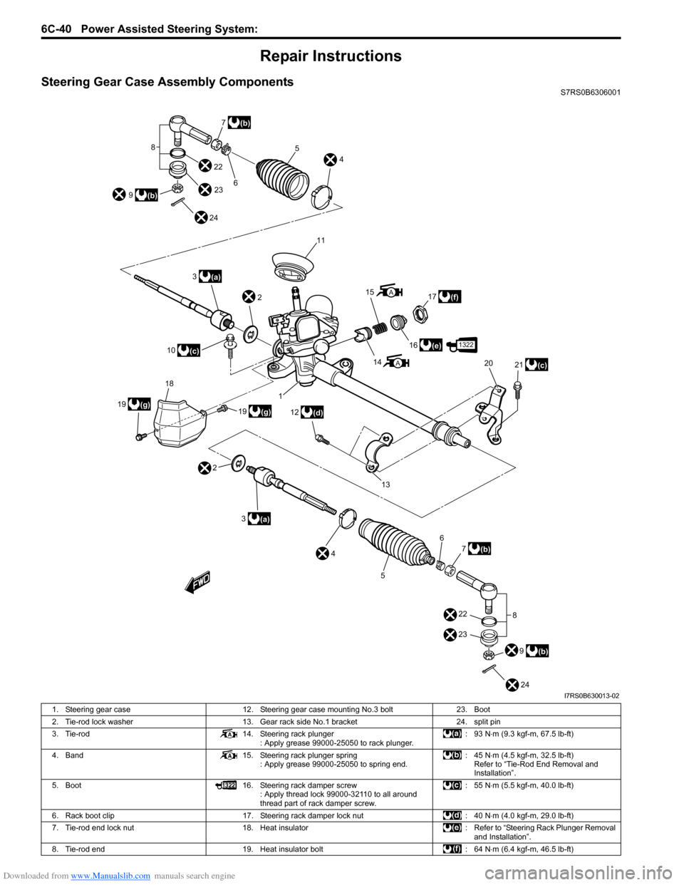
Steering Gear Case Assembly ComponentsS7RS0B6306001
3(a)
10
(c) 2
3
(a)
2 1
19
(g)
19 18(g) 6
11
8
9
(b) 7
(b)
22 23
24 4
5
14
15
16
(e)
17
(f)
12
(d) 21
(c)
20
4 6
5 7
(b)
9
(b)
8
13
22
23
24
A
A
1322
I7RS0B630013-02
1. Steering gear case 12. Steering gear case mounting No.3 bolt 23. Boot
2. Tie-rod lock washer 13. Gear rack side No.1 bracket 24. split pin
3. Tie-rod 14. Steering rack plunger
: Apply grease 99000-25050 to rack plunger. : 93 N
⋅m (9.3 kgf-m, 67.5 lb-ft)
4. Band 15. Steering rack plunger spring
: Apply grease 99000-25050 to spring end. : 45 N
⋅m (4.5 kgf-m, 32.5 lb-ft)
Refer to “Tie-Rod End Removal and
Installation”.
5. Boot 16. Steering rack damper screw
: Apply thread lock 99000-32110 to all around
thread part of rack damper screw. : 55 N
⋅m (5.5 kgf-m, 40.0 lb-ft)
6. Rack boot clip 17. Steering rack damper lock nut : 40 N⋅m (4.0 kgf-m, 29.0 lb-ft)
7. Tie-rod end lock nut 18. Heat insulator : Refer to “Steering Rack Plunger Removal
and Installation”.
8. Tie-rod end 19. Heat insulator bolt : 64 N⋅m (6.4 kgf-m, 46.5 lb-ft)
Page 926 of 1496
Downloaded from www.Manualslib.com manuals search engine 6C-44 Power Assisted Steering System:
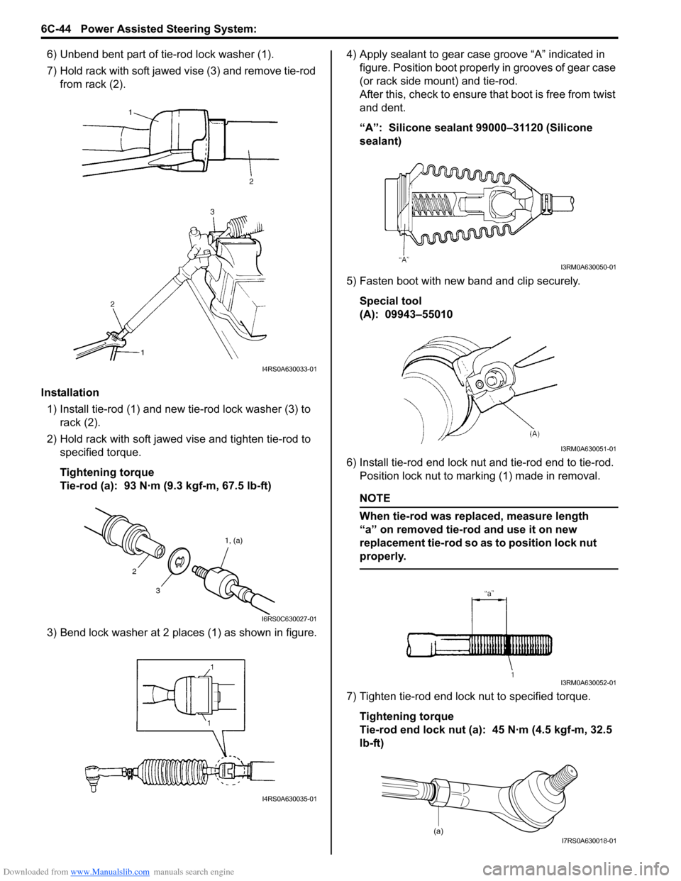
6) Unbend bent part of tie-rod lock washer (1).
7) Hold rack with soft jawed vise (3) and remove tie-rod
from rack (2).
Installation 1) Install tie-rod (1) and new tie-rod lock washer (3) to rack (2).
2) Hold rack with soft jawed vise and tighten tie-rod to specified torque.
Tightening torque
Tie-rod (a): 93 N·m (9.3 kgf-m, 67.5 lb-ft)
3) Bend lock washer at 2 places (1) as shown in figure. 4) Apply sealant to gear case groove “A” indicated in
figure. Position boot properly in grooves of gear case
(or rack side mount) and tie-rod.
After this, check to ensure that boot is free from twist
and dent.
“A”: Silicone sealant 99000–31120 (Silicone
sealant)
5) Fasten boot with new band and clip securely. Special tool
(A): 09943–55010
6) Install tie-rod end lock nut and tie-rod end to tie-rod. Position lock nut to marking (1) made in removal.
NOTE
When tie-rod was replaced, measure length
“a” on removed tie-rod and use it on new
replacement tie-rod so as to position lock nut
properly.
7) Tighten tie-rod end lock nut to specified torque.
Tightening torque
Tie-rod end lock nut (a): 45 N·m (4.5 kgf-m, 32.5
lb-ft)
I4RS0A630033-01
3 1, (a)
2
I6RS0C630027-01
I4RS0A630035-01
I3RM0A630050-01
I3RM0A630051-01
I3RM0A630052-01
(a)I7RS0A630018-01
Page 1034 of 1496
Downloaded from www.Manualslib.com manuals search engine 8A-3 Seat Belts:
Repair Instructions
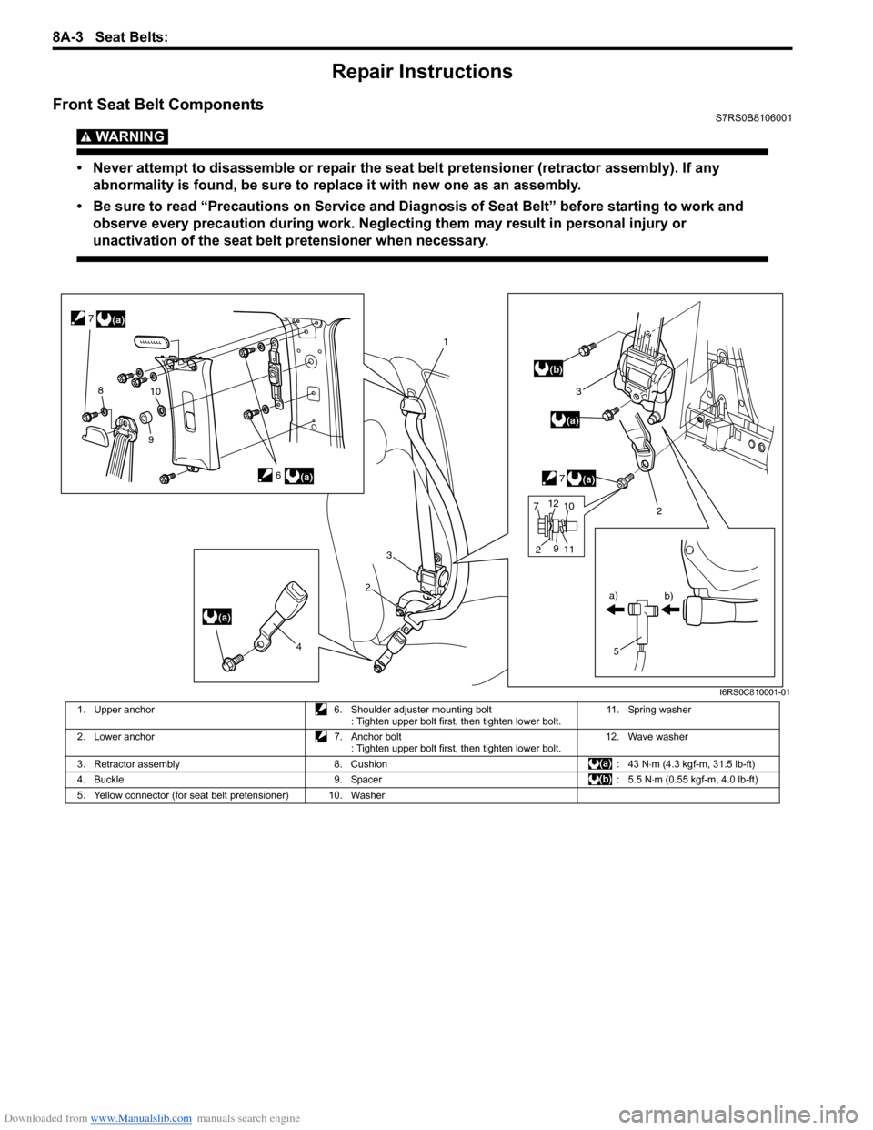
Front Seat Belt ComponentsS7RS0B8106001
WARNING!
• Never attempt to disassemble or repair the seat belt pretensioner (retractor assembly). If any abnormality is found, be sure to replace it with new one as an assembly.
• Be sure to read “Precautions on Service and Diagnosis of Seat Belt” before starting to work and observe every precaution during work. Neglecting them may result in personal injury or
unactivation of the seat belt pretensioner when necessary.
(a)
(a)
(a)
1
2
3
5
a)
b)
(a)
3
7
(b)
6
2
4
(a)
7
810
9
7 2 11
9
1012
I6RS0C810001-01
1. Upper anchor
6. Shoulder adjuster mounting bolt
: Tighten upper bolt first, then tighten lower bolt. 11. Spring washer
2. Lower anchor 7. Anchor bolt
: Tighten upper bolt first, then tighten lower bolt. 12. Wave washer
3. Retractor assembly 8. Cushion : 43 N⋅m (4.3 kgf-m, 31.5 lb-ft)
4. Buckle 9. Spacer : 5.5 N⋅m (0.55 kgf-m, 4.0 lb-ft)
5. Yellow connector (for seat belt pretensioner) 10. Washer