001 SUZUKI SWIFT 2008 2.G Service Workshop Manual
[x] Cancel search | Manufacturer: SUZUKI, Model Year: 2008, Model line: SWIFT, Model: SUZUKI SWIFT 2008 2.GPages: 1496, PDF Size: 34.44 MB
Page 1094 of 1496
Downloaded from www.Manualslib.com manuals search engine 8B-56 Air Bag System:
NOTE
Upon completion of inspection and repair work, perform the following items.
• Reconnect all air bag system components and ensure all components are properly mounted.
• Clear DTCs referring to “DTC Clearance”, if any.
• Repeat “Air Bag Diagnostic System Check” to confirm that the trouble has been corrected.
DTC B1051 / B1055: Driver / Passenger Pretensioner Initiator Circuit Resistance HighS7RS0B8204026
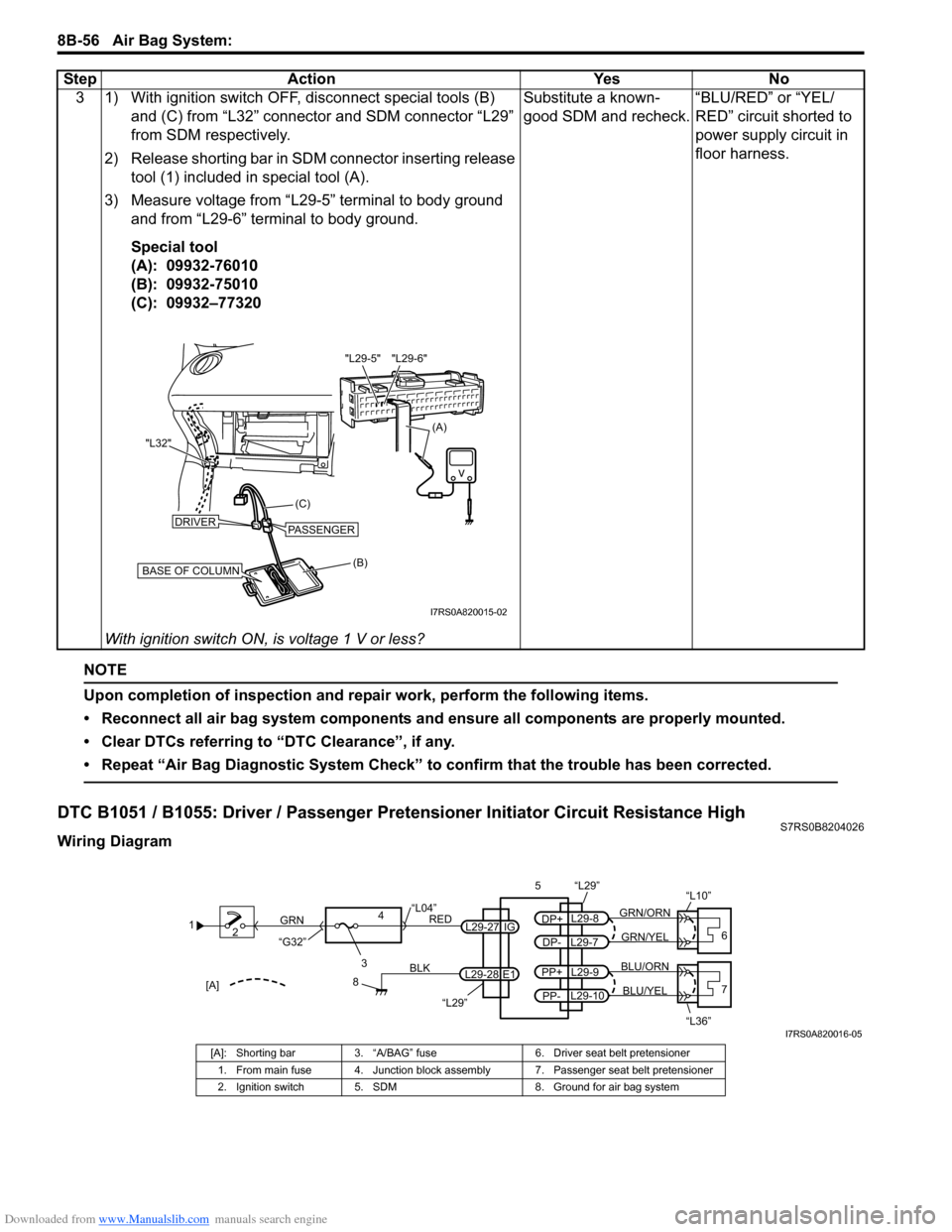
Wiring Diagram3 1) With ignition switch OFF, disconnect special tools (B)
and (C) from “L32” connector and SDM connector “L29”
from SDM respectively.
2) Release shorting bar in SDM connector inserting release tool (1) included in special tool (A).
3) Measure voltage from “L29-5” terminal to body ground and from “L29-6” terminal to body ground.
Special tool
(A): 09932-76010
(B): 09932-75010
(C): 09932–77320
With ignition switch ON, is voltage 1 V or less? Substitute a known-
good SDM and recheck.
“BLU/RED” or “YEL/
RED” circuit shorted to
power supply circuit in
floor harness.
Step Action Yes No
(B)
(C)
"L32"
BASE OF COLUMN
DRIVERPASSENGER
(A)
"L29-6"
"L29-5"
I7RS0A820015-02
1
2
3
GRN
RED
8
BLK
L29-27
L29-28 IG
E1
4
“L29”
“L04”
“G32”
“L29”
L29-8
DP+
L29-7
DP-GRN/YEL
GRN/ORN
56
“L10”
L29-9
PP+
L29-10
PP-BLU/YEL
BLU/ORN7
“L36”[A]
I7RS0A820016-05
[A]: Shorting bar 3. “A/BAG” fuse 6. Driver seat belt pretensioner
1. From main fuse 4. Junction block assembly 7. Passenger seat belt pretensioner
2. Ignition switch 5. SDM 8. Ground for air bag system
Page 1096 of 1496

Downloaded from www.Manualslib.com manuals search engine 8B-58 Air Bag System:
NOTE
Upon completion of inspection and repair work, perform the following items.
• Reconnect all air bag system components and ensure all components are properly mounted.
• Clear DTCs referring to “DTC Clearance”, if any.
• Repeat “Air Bag Diagnostic System Check” to confirm that the trouble has been corrected.
DTC B1052 / B1056: Driver / Passenger Pretensioner Initiator Circuit Resistance LowS7RS0B8204027
Wiring Diagram2 1) With ignition switch OFF, disconnect SDM connector
“29”.
2) Check proper connection to SDM at terminals in “L29-7” and “L29-8” (for DTC B1051) or “L29-9” and “L29-10”
(for DTC B1055).
3) If OK, release shorting bar in SDM connector inserting
release tool (1) included in special tool (A).
4) Measure resistance between “L29-7” and “L29-8” terminals (for DTC B1051) or “L29-9” and “L29-10”
terminals (for DTC B1055) with connected special tools
(B) and (C).
Special tool
(A): 09932-76010
(B): 09932-75010
(C): 09932–78310
Is resistance 2.91
Ω or less? Substitute a known-
good SDM and recheck.
DTC B1051: High
resistance or open wire
in “GRN/ORN” or “GRN/
YEL” circuit.
DTC B1055: High
resistance or open wire
in “BLU/ORN” or “BLU/
YEL” circuit.
Step Action Yes No
(A)
"L29-8" "L29-9" "L29-10"
"L29-7"
STEERING WHEEL(B)
(C)
(A)
"L10", "L36"
I7RS0A820017-03
1
2
3
GRN
RED
8
BLK
L29-27
L29-28 IG
E1
4
“L29”
“L04”
“G32”
“L29”
L29-8
DP+
L29-7
DP-GRN/YEL
GRN/ORN
56
“L10”
L29-9
PP+
L29-10
PP-BLU/YEL
BLU/ORN7
“L36”[A]
I7RS0A820016-05
[A]: Shorting bar 3. “A/BAG” fuse 6. Driver seat belt pretensioner
1. From main fuse 4. Junction block assembly 7. Passenger seat belt pretensioner
2. Ignition switch 5. SDM 8. Ground for air bag system
Page 1098 of 1496

Downloaded from www.Manualslib.com manuals search engine 8B-60 Air Bag System:
NOTE
Upon completion of inspection and repair work, perform the following items.
• Reconnect all air bag system components and ensure all components are properly mounted.
• Clear DTCs referring to “DTC Clearance”, if any.
• Repeat “Air Bag Diagnostic System Check” to confirm that the trouble has been corrected.
DTC B1053 / B1057: Driver / Passenger Pretensioner Initiator Circuit Short to GroundS7RS0B8204028
Wiring Diagram2 1) With ignition switch OFF, disconnect SDM connector
“29”.
2) Check proper connection to SDM at terminals in “L29-7” and “L29-8” (for DTC B1052) or “L29-9” and “L29-10”
(for DTC B1056).
3) If OK, release shorting bar in SDM connector inserting
release tool (1) included in special tool (A).
4) If OK, then measure resistance between “L29-7” and “L29-8” terminals (for DTC B1052) or “L29-9” and “L29-
10” terminals (for DTC B1056) with connected special
tools (B) and (C).
Special tool
(A): 09932-76010
(B): 09932-75010
(C): 09932–78310
Is resistance 1.8
Ω or more? Substitute a known-
good SDM and recheck.
DTC B1052: “GRN/
ORN” circuit shorted to
“GRN/YEL” circuit,
“GRN/ORN” circuit or
“GRN/YEL” circuit
shorted to other circuit.
DTC B1056: “BLU/
ORN” circuit shorted to
“BLU/YEL” circuit, “BLU/
ORN” circuit or “BLU/
YEL” circuit shorted to
other circuit.
Step Action Yes No
(A)
"L29-8" "L29-9" "L29-10"
"L29-7"
STEERING WHEEL(B)
(C)
(A)
"L10", "L36"
I7RS0A820017-03
1
2
3
GRN
RED
8
BLK
L29-27
L29-28 IG
E1
4
“L29”
“L04”
“G32”
“L29”
L29-8
DP+
L29-7
DP-GRN/YEL
GRN/ORN
56
“L10”
L29-9
PP+
L29-10
PP-BLU/YEL
BLU/ORN7
“L36”[A]
I7RS0A820016-05
[A]: Shorting bar 3. “A/BAG” fuse 6. Driver seat belt pretensioner
1. From main fuse 4. Junction block assembly 7. Passenger seat belt pretensioner
2. Ignition switch 5. SDM 8. Ground for air bag system
Page 1100 of 1496
Downloaded from www.Manualslib.com manuals search engine 8B-62 Air Bag System:
NOTE
Upon completion of inspection and repair work, perform the following items.
• Reconnect all air bag system components and ensure all components are properly mounted.
• Clear DTCs referring to “DTC Clearance”, if any.
• Repeat “Air Bag Diagnostic System Check” to confirm that the trouble has been corrected.
DTC B1054 / B1058: Driver / Passenger Pretensioner Initiator Circuit Short to Power CircuitS7RS0B8204029
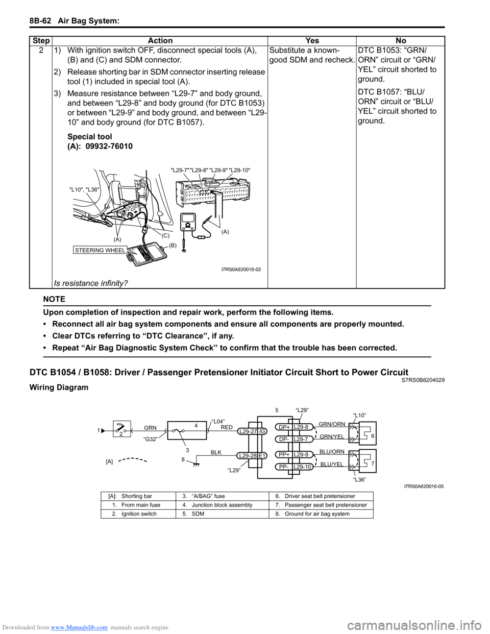
Wiring Diagram2 1) With ignition switch OFF, disconnect special tools (A),
(B) and (C) and SDM connector.
2) Release shorting bar in SDM connector inserting release tool (1) included in special tool (A).
3) Measure resistance between “L29-7” and body ground, and between “L29-8” and body ground (for DTC B1053)
or between “L29-9” and body ground, and between “L29-
10” and body ground (for DTC B1057).
Special tool
(A): 09932-76010
Is resistance infinity? Substitute a known-
good SDM and recheck.
DTC B1053: “GRN/
ORN” circuit or “GRN/
YEL” circuit shorted to
ground.
DTC B1057: “BLU/
ORN” circuit or “BLU/
YEL” circuit shorted to
ground.
Step Action Yes No
"L29-8" "L29-9" "L29-10"
"L29-7"
(A)
STEERING WHEEL(B)
(C)
(A)
"L10", "L36"
I7RS0A820018-02
1
2
3
GRN
RED
8
BLK
L29-27
L29-28 IG
E1
4
“L29”
“L04”
“G32”
“L29”
L29-8
DP+
L29-7
DP-GRN/YEL
GRN/ORN
56
“L10”
L29-9
PP+
L29-10
PP-BLU/YEL
BLU/ORN7
“L36”[A]
I7RS0A820016-05
[A]: Shorting bar 3. “A/BAG” fuse 6. Driver seat belt pretensioner
1. From main fuse 4. Junction block assembly 7. Passenger seat belt pretensioner
2. Ignition switch 5. SDM 8. Ground for air bag system
Page 1102 of 1496
Downloaded from www.Manualslib.com manuals search engine 8B-64 Air Bag System:
NOTE
Upon completion of inspection and repair work, perform the following items.
• Reconnect all air bag system components and ensure all components are properly mounted.
• Clear DTCs referring to “DTC Clearance”, if any.
• Repeat “Air Bag Diagnostic System Check” to confirm that the trouble has been corrected.
DTC B1061 / B1065: Driver / Passenger Side-Air Bag Initiator Circuit Resistance HighS7RS0B8204030
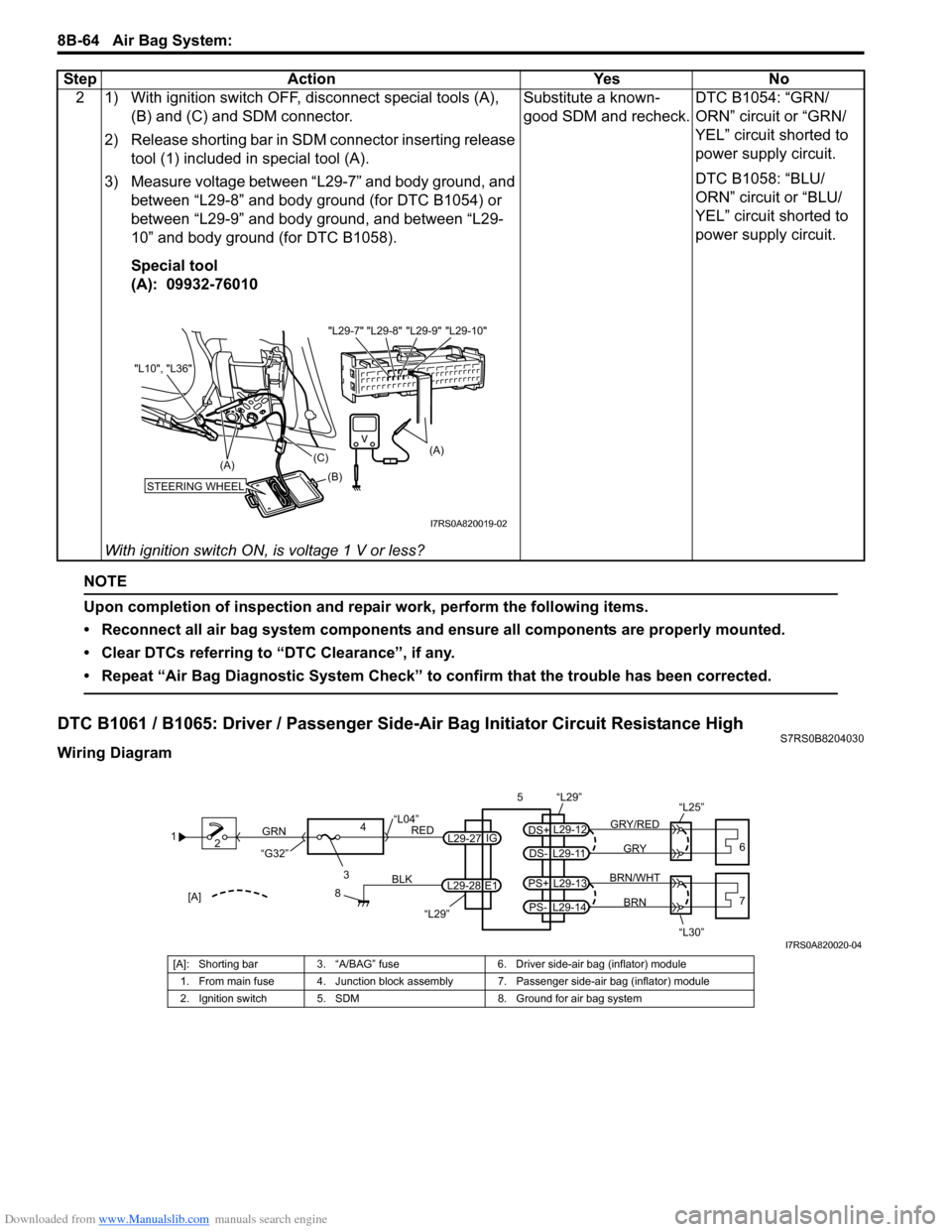
Wiring Diagram2 1) With ignition switch OFF, disconnect special tools (A),
(B) and (C) and SDM connector.
2) Release shorting bar in SDM connector inserting release tool (1) included in special tool (A).
3) Measure voltage between “L29-7” and body ground, and between “L29-8” and body ground (for DTC B1054) or
between “L29-9” and body ground, and between “L29-
10” and body ground (for DTC B1058).
Special tool
(A): 09932-76010
With ignition switch ON, is voltage 1 V or less? Substitute a known-
good SDM and recheck.
DTC B1054: “GRN/
ORN” circuit or “GRN/
YEL” circuit shorted to
power supply circuit.
DTC B1058: “BLU/
ORN” circuit or “BLU/
YEL” circuit shorted to
power supply circuit.
Step Action Yes No
"L29-8" "L29-9" "L29-10"
"L29-7"
(A)
STEERING WHEEL(B)
(C)
(A)
"L10", "L36"
I7RS0A820019-02
1
2
3
GRN
RED
8
BLK
L29-27
L29-28 IG
E1
4
“L29”
“L04”
“G32”
“L29”
L29-12
DS+
L29-11
DS-GRY
GRY/RED
56
“L25”
L29-13
PS+
L29-14
PS-BRN
BRN/WHT7
“L30”[A]
I7RS0A820020-04
[A]: Shorting bar 3. “A/BAG” fuse 6. Driver side-air bag (inflator) module
1. From main fuse 4. Junction block assembly 7. Passenger side-air bag (inflator) module
2. Ignition switch 5. SDM 8. Ground for air bag system
Page 1132 of 1496
Downloaded from www.Manualslib.com manuals search engine 8B-94 Air Bag System:
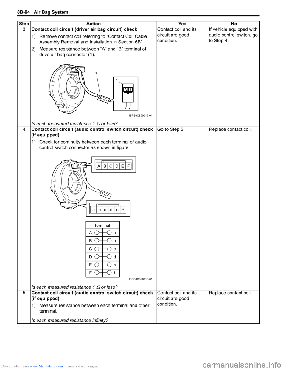
3Contact coil circuit (driver air bag circuit) check
1) Remove contact coil referr ing to “Contact Coil Cable
Assembly Removal and Inst allation in Section 6B”.
2) Measure resistance between “A” and “B” terminal of drive air bag connector (1).
Is each measured resistance 1
Ω or less? Contact coil and its
circuit are good
condition.
If vehicle equipped with
audio control switch, go
to Step 4.
4 Contact coil circuit (audio control switch circuit) check
(if equipped)
1) Check for continuity between each terminal of audio
control switch connector as shown in figure.
Is each measured resistance 1
Ω or less? Go to Step 5. Replace contact coil.
5 Contact coil circuit (audio control switch circuit) check
(if equipped)
1) Measure resistance between each terminal and other
terminal.
Is each measured resistance infinity? Contact coil and its
circuit are good
condition.
Replace contact coil.
Step Action Yes No
1
1
AB
I6RS0C820012-01
ABCDEF
abc de
f
A
Ba
b
C
D c
d
E F e
f
Terminal
I6RS0C820013-01
Page 1136 of 1496
Downloaded from www.Manualslib.com manuals search engine 8B-98 Air Bag System:
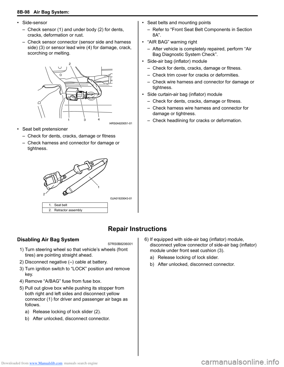
• Side-sensor– Check sensor (1) and under body (2) for dents, cracks, deformation or rust.
– Check sensor connector (sensor side and harness side) (3) or sensor lead wire (4) for damage, crack,
scorching or melting.
• Seat belt pretensioner – Check for dents, cracks , damage or fitness
– Check harness and connector for damage or tightness. • Seat belts and mounting points
– Refer to “Front Seat Belt Components in Section 8A”.
• “AIR BAG” warning right
– After vehicle is completely repaired, perform “Air Bag Diagnostic System Check”.
• Side-air bag (inflator) module – Check for dents, cra cks, damage or fitness.
– Check trim cover for cracks or deformities.
– Check wire harness and connector for damage or tightness.
• Side curtain-air bag (inflator) module – Check for dents, cra cks, damage or fitness.
– Check harness wire harness and connector for damage or tightness.
– Check headlining for cracks or deformation.
Repair Instructions
Disabling Air Bag SystemS7RS0B8206001
1) Turn steering wheel so that vehicle’s wheels (front tires) are pointing straight ahead.
2) Disconnect negative (–) cable at battery.
3) Turn ignition switch to “LOCK” position and remove key.
4) Remove “A/BAG” fu se from fuse box.
5) Pull out glove box while pushing its stopper from
both right and left sides and disconnect yellow
connector (1) for driver and passenger air bags as
follows.
a) Release locking of lock slider (2).
b) After unlocked, disconnect connector. 6) If equipped with side-air bag (inflator) module,
disconnect yellow connector of side-air bag (inflator)
module under front seat cushion (3).
a) Release locking of lock slider.
b) After unlocked, disconnect connector.
1. Seat belt
2. Retractor assembly
13 4
2I4RS0A820051-01
I3JA01820043-01
Page 1155 of 1496
Downloaded from www.Manualslib.com manuals search engine Air Bag System: 8B-117
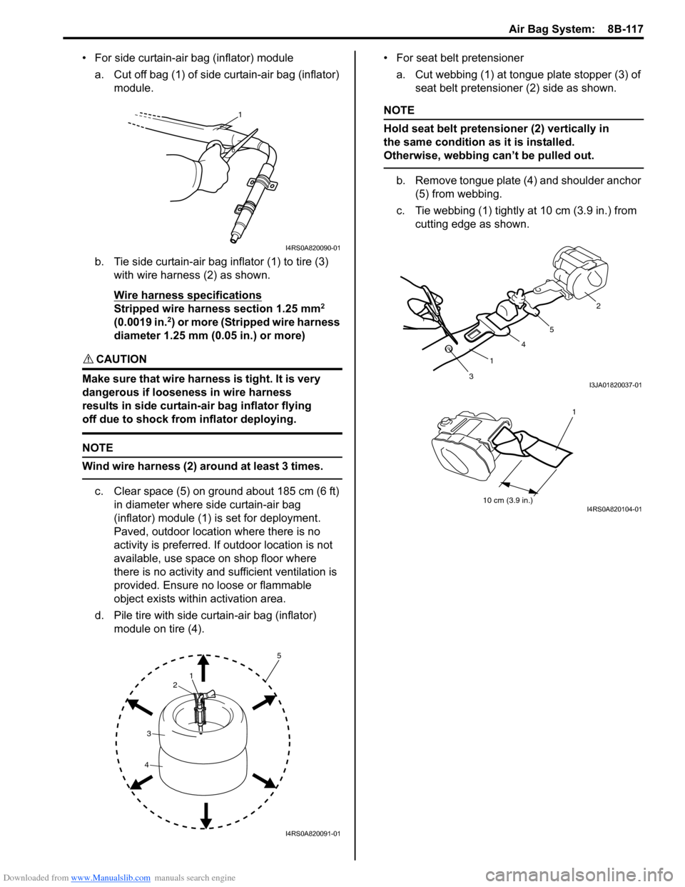
• For side curtain-air bag (inflator) modulea. Cut off bag (1) of side curtain-air bag (inflator) module.
b. Tie side curtain-air bag inflator (1) to tire (3) with wire harness (2) as shown.
Wire harness specifications
Stripped wire harness section 1.25 mm2
(0.0019 in.2) or more (Stripped wire harness
diameter 1.25 mm (0.05 in.) or more)
CAUTION!
Make sure that wire harness is tight. It is very
dangerous if looseness in wire harness
results in side curtain-air bag inflator flying
off due to shock from inflator deploying.
NOTE
Wind wire harness (2) around at least 3 times.
c. Clear space (5) on ground about 185 cm (6 ft) in diameter where side curtain-air bag
(inflator) module (1) is set for deployment.
Paved, outdoor location where there is no
activity is preferred. If outdoor location is not
available, use space on shop floor where
there is no activity and sufficient ventilation is
provided. Ensure no loose or flammable
object exists within activation area.
d. Pile tire with side curtain-air bag (inflator) module on tire (4). • For seat belt pretensioner
a. Cut webbing (1) at tongue plate stopper (3) of seat belt pretensioner (2) side as shown.
NOTE
Hold seat belt pretensioner (2) vertically in
the same condition as it is installed.
Otherwise, webbing can’t be pulled out.
b. Remove tongue plate (4) and shoulder anchor (5) from webbing.
c. Tie webbing (1) tightly at 10 cm (3.9 in.) from
cutting edge as shown.
1
I4RS0A820090-01
1
2
3
4
5
I4RS0A820091-01
3 1 4
5 2I3JA01820037-01
10 cm (3.9 in.)
1
I4RS0A820104-01
Page 1156 of 1496
Downloaded from www.Manualslib.com manuals search engine 8B-118 Air Bag System:
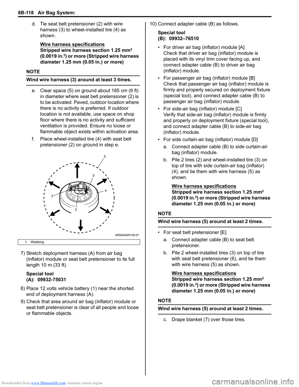
d. Tie seat belt pretensioner (2) with wire harness (3) to wheel-installed tire (4) as
shown.
Wire harness specifications
Stripped wire harness section 1.25 mm2
(0.0019 in.2) or more (Stripped wire harness
diameter 1.25 mm (0.05 in.) or more)
NOTE
Wind wire harness (3) around at least 3 times.
e. Clear space (5) on ground about 185 cm (6 ft) in diameter where seat belt pretensioner (2) is
to be activated. Paved, outdoor location where
there is no activity is preferred. If outdoor
location is not available, use space on shop
floor where there is no activity and sufficient
ventilation is provided. Ensure no loose or
flammable object exists within activation area.
f. Place wheel-installed tire (4) with seat belt pretensioner (2) on ground in step e.
7) Stretch deployment harness (A) from air bag (inflator) module or seat belt pretensioner to its full
length 10 m (33 ft).
Special tool
(A): 09932-75031
8) Place 12 volts vehicle battery (1) near the shorted end of deployment harness (A).
9) Check that area around air bag (inflator) module or seat belt pretensioner is clear of all people and loose
or flammable objects. 10) Connect adapter cable (B) as follows.
Special tool
(B): 09932–76510
• For driver air bag (inflator) module [A]Check that driver air bag (inflator) module is
placed with its vinyl trim cover facing up, and
connect adapter cable (B) to driver air bag
(inflator) module.
• For passenger air bag (inflator) module [B] Check that passenger air bag (inflator) module is
firmly and properly secured on deployment fixture
(special tool), and connect adapter cable (B) to
passenger air bag (inflator) module.
• For side-air bag (inflator) module [C] Verify that side-air bag (inflator) module is firmly
and properly on deployment fixture (special tool),
and connect adapter cable (B) to side-air bag
(inflator) module.
• For side curtain-air bag (inflator) module [D] a. Connect adapter cable (B) to side curtain-air bag (inflator) module.
b. Pile 2 tires (2) and wheel-installed tire (3) on top of tire with side curtain-air bag (inflator)
(4), and tie them with wire harness (5) as
shown.
Wire harness specifications
Stripped wire harness section 1.25 mm2
(0.0019 in.2) or more (Stripped wire harness
diameter 1.25 mm (0.05 in.) or more)
NOTE
Wind wire harness (5) around at least 2 times.
• For seat belt pretensioner [E]
a. Connect adapter cable (B) to seat belt pretensioner.
b. Pile 2 wheel-installed tires (3) on top of tire with seat belt pretensioner (6), and tie them
with wire harness (5) as shown.
Wire harness specifications
Stripped wire harness section 1.25 mm2
(0.0019 in.2) or more (Stripped wire harness
diameter 1.25 mm (0.05 in.) or more)
NOTE
Wind wire harness (5) around at least 2 times.
c. Drape blanket (7) over those tires.
1. Webbing
4
3
3 2 5
I4RS0A820105-01
Page 1163 of 1496
Downloaded from www.Manualslib.com manuals search engine Air Bag System: 8B-125
Specifications
Tightening Torque SpecificationsS7RS0B8207001
NOTE
The specified tightening torque is also described in the following.
“Air Bag System Components, Wiring and Connectors Location”
Reference:
For the tightening torque of fastener not specified in this section, refer to “Fasteners Information in Section 0A”.
Special Tools and Equipment
Use of Special ToolsS7RS0B8208001
WARNING!
To avoid deployment when troubleshooting
the air bag system, do not use electrical test
equipment such as a battery powered or AC
powered voltmeter, ohmmeter, etc., or any
type of electrical equipment other than that
specified. Do not use a non-powered probe
type tester.
Instructions must be followed carefully,
otherwise personal injury may result.
You should be familiar with the tools listed under the
heading “Special Tool”. You should be able to measure
voltage and resistance. You should be familiar with
proper use of a scan tool such as Air Bag Driver /
Passenger Load Tool, Connector Test Adapter Kit and
the Digital Multimeter.
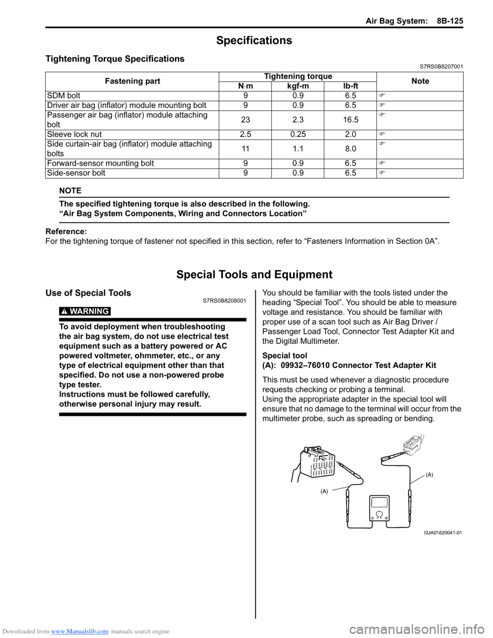
Special tool
(A): 09932–76010 Connector Test Adapter Kit
This must be used whenever a diagnostic procedure
requests checking or probing a terminal.
Using the appropriate adapter in the special tool will
ensure that no damage to the terminal will occur from the
multimeter probe, such as spreading or bending.
Fastening part
Tightening torque
Note
N ⋅mkgf-mlb-ft
SDM bolt 9 0.9 6.5 �)
Driver air bag (inflator) module mounting bolt 9 0.9 6.5 �)
Passenger air bag (inflator) module attaching
bolt 23 2.3 16.5�)
Sleeve lock nut 2.5 0.25 2.0 �)
Side curtain-air bag (inflator) module attaching
bolts 11 1.1 8.0�)
Forward-sensor mounting bolt 9 0.9 6.5 �)
Side-sensor bolt 9 0.9 6.5 �)
I3JA01820041-01