001 SUZUKI SWIFT 2008 2.G Service Workshop Manual
[x] Cancel search | Manufacturer: SUZUKI, Model Year: 2008, Model line: SWIFT, Model: SUZUKI SWIFT 2008 2.GPages: 1496, PDF Size: 34.44 MB
Page 1393 of 1496
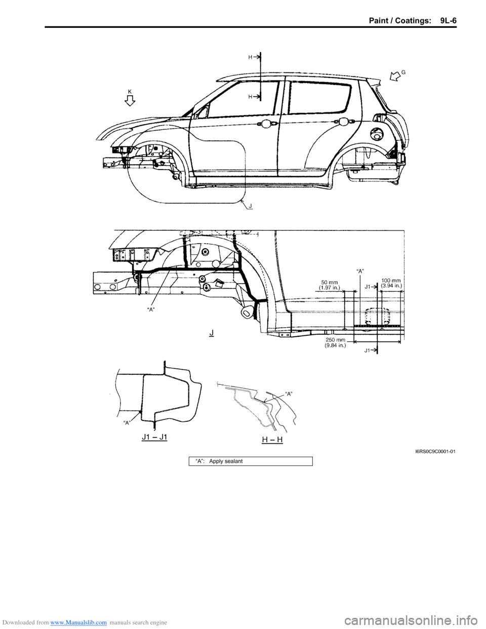
Downloaded from www.Manualslib.com manuals search engine Paint / Coatings: 9L-6
I6RS0C9C0001-01
“A”: Apply sealant
Page 1395 of 1496

Downloaded from www.Manualslib.com manuals search engine Paint / Coatings: 9L-8
Under Coating Application AreasS7RS0B9C03002
I7RS0B9C0001-01
“A”: Apply undercoating (PVC, 400 µm or more). “C”: Apply undercoating (PVC, 400 µm or more) covering flange end.
“B”: Do not apply undercoating. “D”: Apply undercoating (PVC, 400 µm or more) after painted black paint.
Page 1398 of 1496
![SUZUKI SWIFT 2008 2.G Service Workshop Manual Downloaded from www.Manualslib.com manuals search engine 9M-1 Exterior Trim:
Body, Cab and Accessories
Exterior Trim
Repair Instructions
Roof Molding ComponentsS7RS0B9D06001
42
2
1
3
[A]
2
53 mm (2.0 SUZUKI SWIFT 2008 2.G Service Workshop Manual Downloaded from www.Manualslib.com manuals search engine 9M-1 Exterior Trim:
Body, Cab and Accessories
Exterior Trim
Repair Instructions
Roof Molding ComponentsS7RS0B9D06001
42
2
1
3
[A]
2
53 mm (2.0](/img/20/7607/w960_7607-1397.png)
Downloaded from www.Manualslib.com manuals search engine 9M-1 Exterior Trim:
Body, Cab and Accessories
Exterior Trim
Repair Instructions
Roof Molding ComponentsS7RS0B9D06001
42
2
1
3
[A]
2
53 mm (2.09 in.)
I6RS0C9D0001-01
[A]: Roof side weather-strip installation position
3. Roof molding clip (Push-in type)
: Install roof molding clip to specified position on body with epoxy adhesive applied.
1. Roof molding 4. Windshield side garnish
2. Roof side weather-strip
Page 1403 of 1496

Downloaded from www.Manualslib.com manuals search engine Precautions: 10-1
Control Systems
Precautions
Precautions
Precautions for Control SystemsS7RS0BA000001
Air Bag Warning
Refer to “Air Bag Warning in Section 00”.
Page 1404 of 1496
Downloaded from www.Manualslib.com manuals search engine 10B-1 Body Electrical Control System:
Control Systems
Body Electrical Control System
Precautions
Precautions in Diagnosing TroubleS7RS0BA200001
• Diagnostic information stored in BCM memory can be cleared as well as checked by using SUZUKI scan tool.
Before using scan tool, read its Operator ’s (Instruction) Manual carefully to have good understanding as to what
functions are available and how to use it.
• Be sure to read “Precautions for Electrical Circuit Serv ice in Section 00” before inspection and observe what is
written there.
• Communication of ECM, TCM (if equipped), ABS/ESP ® control module, steering angle sensor (ESP ® model),
keyless start control module (if equipped), combinatio n meter and BCM is established by CAN (Controller Area
Network). For detail of CAN communication for BCM, refer to “CAN Communication System Description”.
Therefore, handle CAN communication line with care referr ing to “Precaution for CAN Communication System in
Section 00”.
General Description
BCM General DescriptionS7RS0BA201001
The Body electrical Control Module (BCM) is incorporated in junction block assembly. Do not attempt removal of BCM
from junction block assembly as it may cause contact failure.
The BCM incorporates relays and controllers which are used for the following systems and controls them.
• Power door lock
• Keyless entry (if equipped)
• Door lock function of keyle ss start system (if equipped)
• Rear wiper
• Combination meter
• Interior light
• Warning buzzer
• Rear end door window defogger and door mirror heater (if equipped)
• Rear end door opener
• Theft deterrent light
Also, the BCM has a function to cause the interior light and open door warning lamp in the combination meter to turn
off when any door is left open for longer than 15 minutes to reduce wasteful battery consumption.
In addition, it is possible to check operation of actuator whic h is controlled by BCM by using the output test function of
SUZUKI scan tool to operate actuator simulatively.
Page 1405 of 1496
Downloaded from www.Manualslib.com manuals search engine Body Electrical Control System: 10B-2
CAN Communication System DescriptionS7RS0BA201002
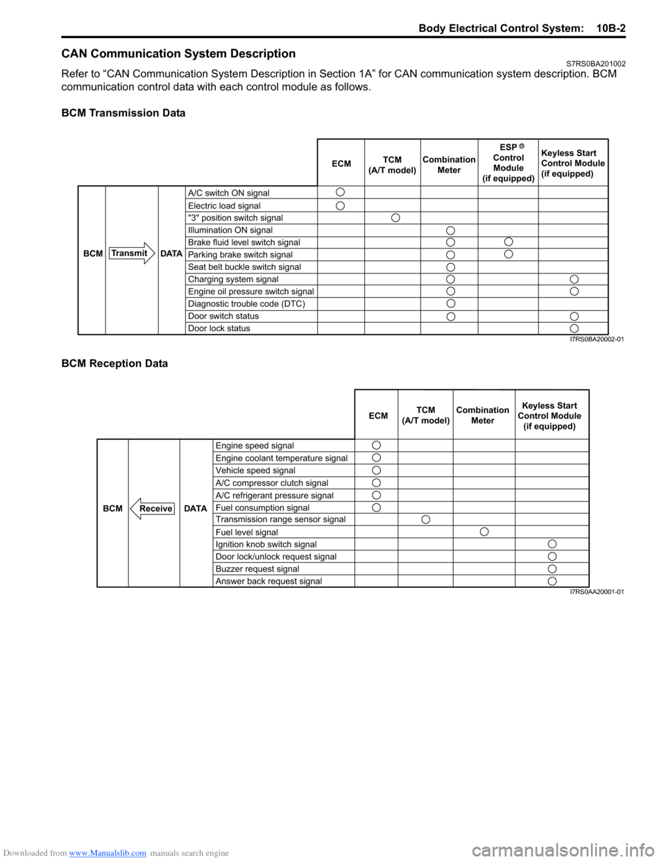
Refer to “CAN Communication System Description in Section 1A” for CAN communication system description. BCM
communication control data with ea ch control module as follows.
BCM Transmission Data
BCM Reception Data
A/C switch ON signal
Electric load signal
"3" position switch signal
Illumination ON signal
Brake fluid level switch signal
Parking brake switch signal
Seat belt buckle switch signal
Charging system signal
Engine oil pressure switch signal
Diagnostic trouble code (DTC)
Door switch status
Door lock status ECM
TCM
(A/T model) Combination
Meter Keyless Start
Control Module
(if equipped)
Transmit DATA
BCM
ESP
Control Module
(if equipped)
I7RS0BA20002-01
Engine speed signal
Vehicle speed signal Engine coolant temperature signal
A/C refrigerant pressure signal
Fuel consumption signal A/C compressor clutch signal
Transmission range sensor signal
Fuel level signal
Ignition knob switch signal
Door lock/unlock request signal
Buzzer request signal
Answer back request signal
DATA
BCM
Receive
Combination
Meter
TCM
(A/T model) Keyless Start
Control Module (if equipped)
ECM
I7RS0AA20001-01
Page 1407 of 1496
Downloaded from www.Manualslib.com manuals search engine Body Electrical Control System: 10B-4
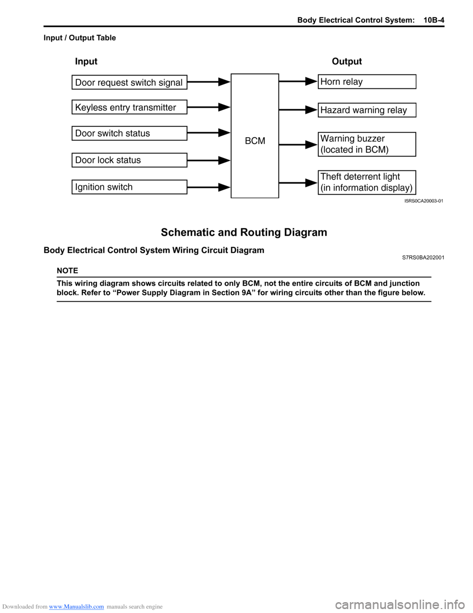
Input / Output Table
Schematic and Routing Diagram
Body Electrical Control System Wiring Circuit DiagramS7RS0BA202001
NOTE
This wiring diagram shows circuits related to only BCM, not the entire circuits of BCM and junction
block. Refer to “Power Supply Diagram in Section 9A” for wiring circuits other than the figure below.
Input Output
Keyless entry transmitter
Door switch status
Door lock status BCMHorn relay
Theft deterrent light
(in information display)
Warning buzzer
(located in BCM)
Hazard warning relay
Door request switch signal
Ignition switch
I5RS0CA20003-01
Page 1411 of 1496
Downloaded from www.Manualslib.com manuals search engine Body Electrical Control System: 10B-8
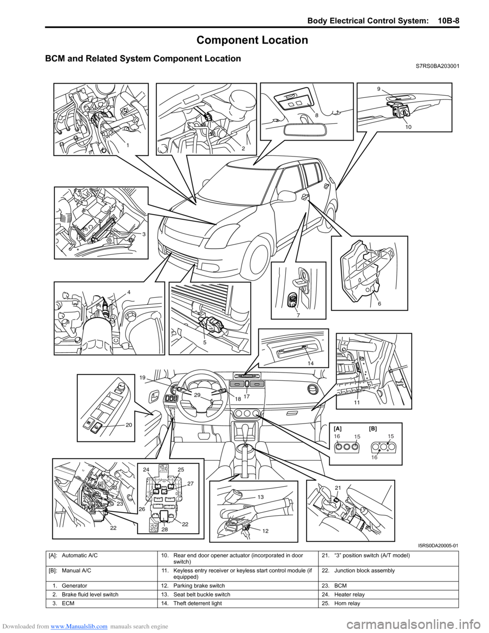
Component Location
BCM and Related System Component LocationS7RS0BA203001
3
4
5
7
6
1117
1829
19
14
20
21
24
25
26 27
28 22
23
22
1
2
8
9
10
1312
151615
16
[A] [B]
I5RS0DA20005-01
[A]: Automatic A/C
10. Rear end door opener actuator (incorporated in door
switch) 21. “3” position switch (A/T model)
[B]: Manual A/C 11. Keyless entry receiver or keyless start control module (if
equipped) 22. Junction block assembly
1. Generator 12. Parking brake switch 23. BCM
2. Brake fluid level switch 13. Seat belt buckle switch 24. Heater relay
3. ECM 14. Theft deterrent light 25. Horn relay
Page 1412 of 1496
Downloaded from www.Manualslib.com manuals search engine 10B-9 Body Electrical Control System:
Diagnostic Information and Procedures
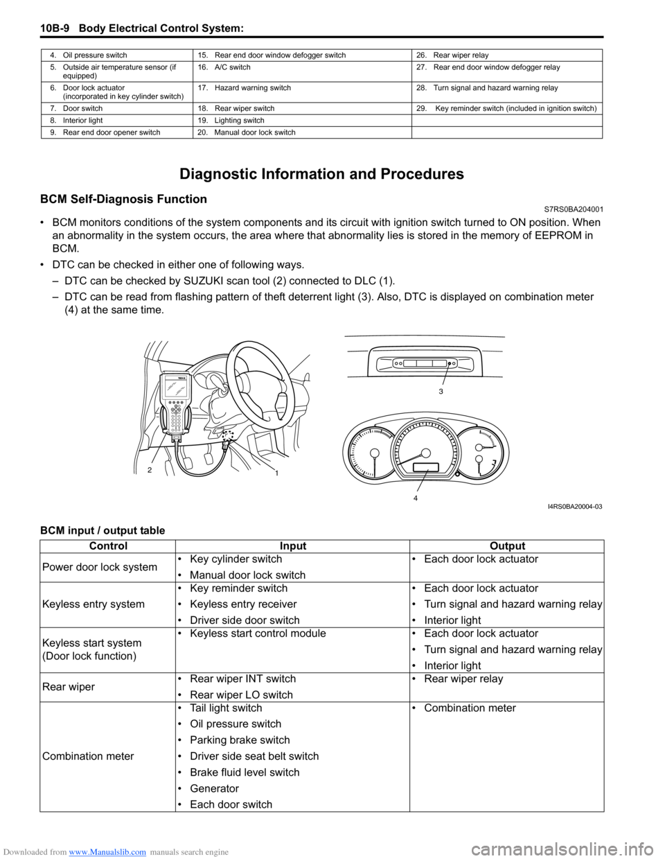
BCM Self-Diagnosis FunctionS7RS0BA204001
• BCM monitors conditions of the system components and its circuit with ignition switch turned to ON position. When
an abnormality in the system oc curs, the area where that abnormality lies is stored in the memory of EEPROM in
BCM.
• DTC can be checked in either one of following ways. – DTC can be checked by SUZUKI scan tool (2) connected to DLC (1).
– DTC can be read from flashing pattern of theft deterrent light (3). Also, DTC is displayed on combination meter
(4) at the same time.
BCM input / output table
4. Oil pressure switch 15. Rear end door window defogger switch 26. Rear wiper relay
5. Outside air temperature sensor (if equipped) 16. A/C switch
27. Rear end door window defogger relay
6. Door lock actuator (incorporated in key cylinder switch) 17. Hazard warning switch
28. Turn signal and hazard warning relay
7. Door switch 18. Rear wiper switch 29. Key reminder switch (included in ignition switch)
8. Interior light 19. Lighting switch
9. Rear end door opener switch 20. Manual door lock switch
3
1
2
4I4RS0BA20004-03
Control
Input Output
Power door lock system • Key cylinder switch
• Manual door lock switch • Each door lock actuator
Keyless entry system • Key reminder switch
• Keyless entry receiver
• Driver side door switch • Each door lock actuator
• Turn signal and hazard warning relay
• Interior light
Keyless start system
(Door lock function) • Keyless start control module
• Each door lock actuator
• Turn signal and hazard warning relay
• Interior light
Rear wiper • Rear wiper INT switch
• Rear wiper LO switch • Rear wiper relay
Combination meter • Tail light switch
• Oil pressure switch
• Parking brake switch
• Driver side seat belt switch
• Brake fluid level switch
• Generator
• Each door switch • Combination meter
Page 1421 of 1496
Downloaded from www.Manualslib.com manuals search engine Body Electrical Control System: 10B-18
DTC B1141 / DTC B1142 (No. 1141 / No. 1142): Outside Air Temperature (Ambient Temp.) Sensor
Circuit Malfunction
S7RS0BA204009
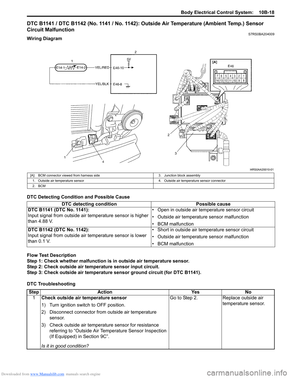
Wiring Diagram
DTC Detecting Condition and Possible Cause
Flow Test Description
Step 1: Check whether malfunction is in outside air temperature sensor.
Step 2: Check outside air temperature sensor input circuit.
Step 3: Check outside air temperature sensor ground circuit (for DTC B1141).
DTC Troubleshooting
I4RS0AA20010-01
[A]: BCM connector viewed from harness side 3. Junction block assembly
1. Outside air temperature sensor 4. Outside air temperature sensor connector
2. BCM
DTC detecting condition Possible cause
DTC B1141 (DTC No. 1141):
Input signal from outside air temperature sensor is higher
than 4.88 V. • Open in outside air temperature sensor circuit
• Outside air temperature sensor malfunction
• BCM malfunction
DTC B1142 (DTC No. 1142):
Input signal from outside air temperature sensor is lower
than 0.1 V. • Short in outside air temperature sensor circuit
• Outside air temperature sensor malfunction
• BCM malfunction
Step
Action YesNo
1 Check outside air temperature sensor
1) Turn ignition switch to OFF position.
2) Disconnect connector from outside air temperature
sensor.
3) Check outside air temperature sensor for resistance referring to “Outside Air Temperature Sensor Inspection
(If Equipped) in Section 9C”.
Is it in good condition? Go to Step 2.
Replace outside air
temperature sensor.