Engine cover SUZUKI SWIFT 2008 2.G Service Repair Manual
[x] Cancel search | Manufacturer: SUZUKI, Model Year: 2008, Model line: SWIFT, Model: SUZUKI SWIFT 2008 2.GPages: 1496, PDF Size: 34.44 MB
Page 427 of 1496
Downloaded from www.Manualslib.com manuals search engine Exhaust System: 1K-4
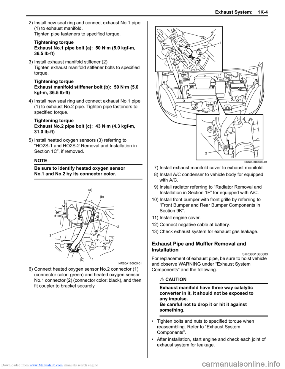
2) Install new seal ring and connect exhaust No.1 pipe (1) to exhaust manifold.
Tighten pipe fasteners to specified torque.
Tightening torque
Exhaust No.1 pipe bolt (a): 50 N·m (5.0 kgf-m,
36.5 lb-ft)
3) Install exhaust manifold stiffener (2). Tighten exhaust manifold stiffener bolts to specified
torque.
Tightening torque
Exhaust manifold stiffener bolt (b): 50 N·m (5.0
kgf-m, 36.5 lb-ft)
4) Install new seal ring and connect exhaust No.1 pipe (1) to exhaust No.2 pipe. Tighten pipe fasteners to
specified torque.
Tightening torque
Exhaust No.2 pipe bolt (c): 43 N·m (4.3 kgf-m,
31.0 lb-ft)
5) Install heated oxygen sensors (3) referring to “HO2S-1 and HO2S-2 Removal and Installation in
Section 1C”, if removed.
NOTE
Be sure to identify heated oxygen sensor
No.1 and No.2 by its connector color.
6) Connect heated oxygen sensor No.2 connector (1)
(connector color: green) and heated oxygen sensor
No.1 connector (2) (connector color: black), and then
fit coupler to br acket securely. 7) Install exhaust manifold cover to exhaust manifold.
8) Install A/C condenser to vehicle body for equipped
with A/C.
9) Install radiator referrin g to “Radiator Removal and
Installation in Section 1F” for equipped with A/C.
10) Install front bumper with fr ont grille by referring to
“Front Bumper and Rear Bumper Components in
Section 9K”.
11) Install engine cover.
12) Connect negative cable at battery.
13) Check exhaust system for exhaust gas leakage.
Exhaust Pipe and Muffler Removal and
Installation
S7RS0B1B06003
For replacement of exhaust pipe, be sure to hoist vehicle
and observe WARNING under “Exhaust System
Components” and the following.
CAUTION!
Exhaust manifold have three way catalytic
converter in it, it should not be exposed to
any impulse.
Be careful not to drop it or hit it against
something.
• Tighten bolts and nuts to specified torque when reassembling. Refer to “Exhaust System
Components”.
• After installation, start engine and check each joint of exhaust system for leakage.
2
(b)
(a)
1(C)
3
I4RS0A1B0005-01
1
2
I6RS0C1B0002-01
Page 437 of 1496
Downloaded from www.Manualslib.com manuals search engine Front Suspension: 2B-4
Reference Information
Side slip
When checked with side slip tester, side slip should
satisfy following specification.Side slip
0 to IN 3.0 mm/m (0 to IN 0.118 in/3.3 ft)
If side slip is greatly di
fferent, toe or front wheel
alignment may not be correct.
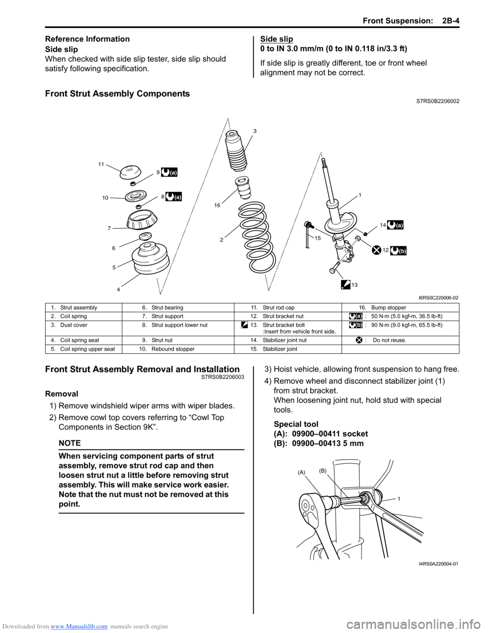
Front Strut Assembly ComponentsS7RS0B2206002
Front Strut Assembly Removal and InstallationS7RS0B2206003
Removal
1) Remove windshield wipe r arms with wiper blades.
2) Remove cowl top covers referring to “Cowl Top
Components in Section 9K”.
NOTE
When servicing component parts of strut
assembly, remove stru t rod cap and then
loosen strut nut a little before removing strut
assembly. This will make service work easier.
Note that the nut must not be removed at this
point.
3) Hoist vehicle, allowing front suspension to hang free.
4) Remove wheel and disconn ect stabilizer joint (1)
from strut bracket.
When loosening joint nu t, hold stud with special
tools.
Special tool
(A): 09900–00411 socket
(B): 09900–00413 5 mm
11 3
2 1
12
13
4
5
6
7
10
8(a)
(b)
9
(a)
14
15(a)
16
I6RS0C220006-02
1. Strut assembly
6. Strut bearing 11. Strut rod cap16. Bump stopper
2. Coil spring 7. Strut support 12. Strut bracket nut : 50 N⋅m (5.0 kgf-m, 36.5 lb-ft)
3. Dust cover 8. Strut support lower nut 13. Strut bracket bolt
:Insert from vehicle front side. : 90 N
⋅m (9.0 kgf-m, 65.5 lb-ft)
4. Coil spring seat 9. Strut nut 14. Stabilizer joint nut : Do not reuse.
5. Coil spring upper seat 10. Rebound stopper 15. Stabilizer joint
1
(A)
(B)
I4RS0A220004-01
Page 441 of 1496
Downloaded from www.Manualslib.com manuals search engine Front Suspension: 2B-8
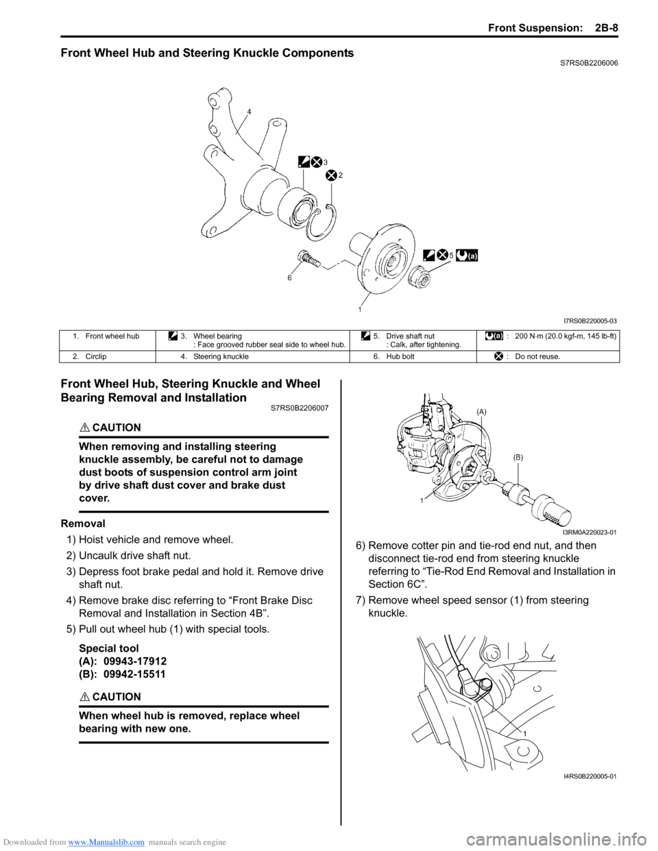
Front Wheel Hub and Steering Knuckle ComponentsS7RS0B2206006
Front Wheel Hub, Steering Knuckle and Wheel
Bearing Removal and Installation
S7RS0B2206007
CAUTION!
When removing and installing steering
knuckle assembly, be careful not to damage
dust boots of suspension control arm joint
by drive shaft dust cover and brake dust
cover.
Removal1) Hoist vehicle and remove wheel.
2) Uncaulk drive shaft nut.
3) Depress foot brake pedal and hold it. Remove drive shaft nut.
4) Remove brake disc referring to “Front Brake Disc Removal and Installa tion in Section 4B”.
5) Pull out wheel hub (1) with special tools.
Special tool
(A): 09943-17912
(B): 09942-15511
CAUTION!
When wheel hub is removed, replace wheel
bearing with new one.
6) Remove cotter pin and tie-rod end nut, and then disconnect tie-rod end from steering knuckle
referring to “Tie-Rod End Removal and Installation in
Section 6C”.
7) Remove wheel speed sensor (1) from steering knuckle.
I7RS0B220005-03
1. Front wheel hub 3. Wheel bearing
: Face grooved rubber seal side to wheel hub. 5. Drive shaft nut
: Calk, after tightening. : 200 N
⋅m (20.0 kgf-m, 145 lb-ft)
2. Circlip 4. Steering knuckle 6. Hub bolt: Do not reuse.
I3RM0A220023-01
1
I4RS0B220005-01
Page 442 of 1496
Downloaded from www.Manualslib.com manuals search engine 2B-9 Front Suspension:
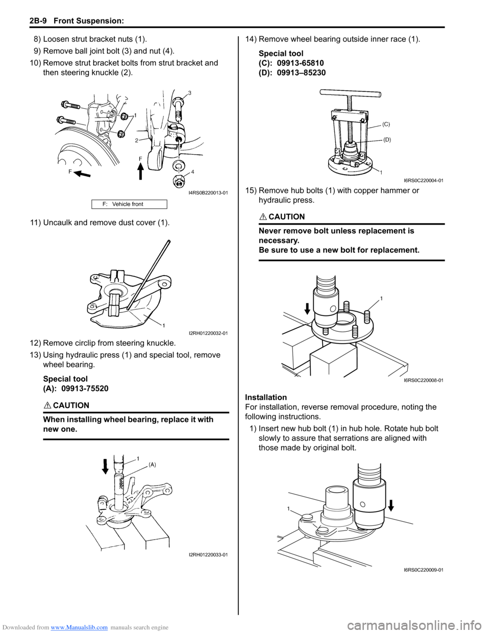
8) Loosen strut bracket nuts (1).
9) Remove ball joint bolt (3) and nut (4).
10) Remove strut bracket bolt s from strut bracket and
then steering knuckle (2).
11) Uncaulk and remove dust cover (1).
12) Remove circlip from steering knuckle.
13) Using hydraulic press (1) and special tool, remove wheel bearing.
Special tool
(A): 09913-75520
CAUTION!
When installing wheel bearing, replace it with
new one.
14) Remove wheel bearing outside inner race (1).
Special tool
(C): 09913-65810
(D): 09913–85230
15) Remove hub bolts (1) with copper hammer or hydraulic press.
CAUTION!
Never remove bolt unle ss replacement is
necessary.
Be sure to use a new bolt for replacement.
Installation
For installation, reverse removal procedure, noting the
following instructions.
1) Insert new hub bolt (1) in hub hole. Rotate hub bolt slowly to assure that serrations are aligned with
those made by original bolt.
F: Vehicle front
I4RS0B220013-01
I2RH01220032-01
I2RH01220033-01
I6RS0C220004-01
1
I6RS0C220008-01
1
I6RS0C220009-01
Page 443 of 1496
Downloaded from www.Manualslib.com manuals search engine Front Suspension: 2B-10
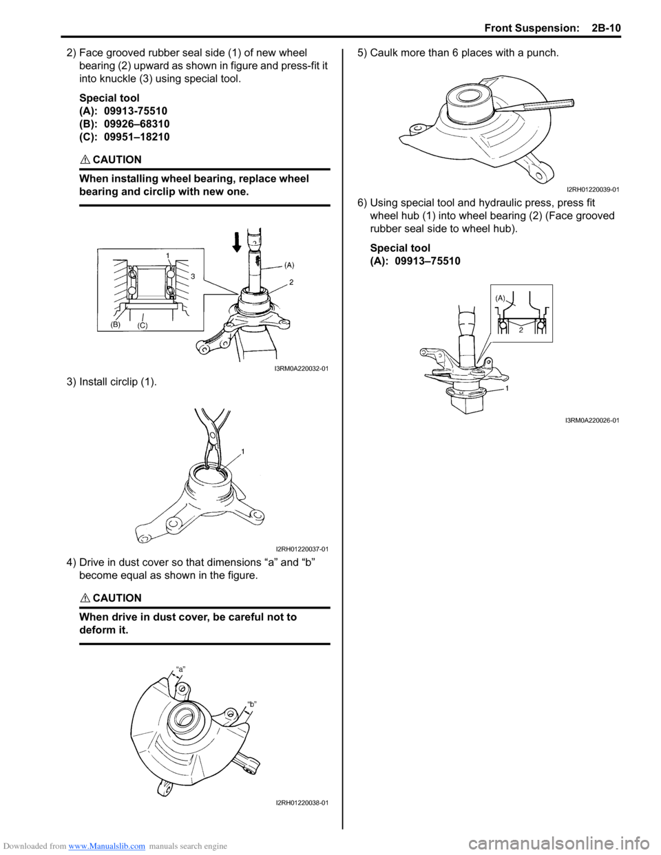
2) Face grooved rubber seal side (1) of new wheel bearing (2) upward as shown in figure and press-fit it
into knuckle (3) using special tool.
Special tool
(A): 09913-75510
(B): 09926–68310
(C): 09951–18210
CAUTION!
When installing wheel bearing, replace wheel
bearing and circlip with new one.
3) Install circlip (1).
4) Drive in dust cover so that dimensions “a” and “b” become equal as shown in the figure.
CAUTION!
When drive in dust cover, be careful not to
deform it.
5) Caulk more than 6 places with a punch.
6) Using special tool and hydraulic press, press fit
wheel hub (1) into wheel bearing (2) (Face grooved
rubber seal side to wheel hub).
Special tool
(A): 09913–75510
I3RM0A220032-01
I2RH01220037-01
I2RH01220038-01
I2RH01220039-01
I3RM0A220026-01
Page 445 of 1496
Downloaded from www.Manualslib.com manuals search engine Front Suspension: 2B-12
Front Wheel Hub, Disc, Nut and Bearing CheckS7RS0B2206008
• Inspect each wheel disc for dents, distortion and cracks.
A disc in badly damaged condition must be replaced.
• Check rust of installation face inside of wheel disc.
As rust affects adversely, remove it thoroughly.
• Check wheel nuts for tightness and, as necessary, retighten them to specification.
• Check wheel bolt press-fitted into wheel hub for wear, damage, poor thread condition, and looseness.
Replace defective bolt with a new one.
When bolt installation is found loose, replace both bolt
and wheel hub with new ones.
Tightening torque
Wheel nut: 85 N·m (8.5 kgf-m, 61.5 lb-ft)
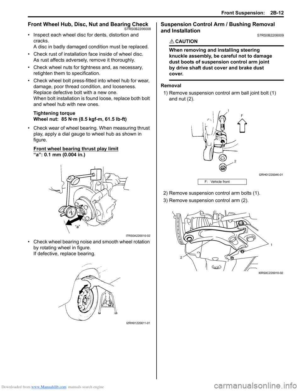
• Check wear of wheel bearing. When measuring thrust play, apply a dial gauge to wheel hub as shown in
figure.
Front wheel bearing thrust play limit
“a”: 0.1 mm (0.004 in.)
• Check wheel bearing noise and smooth wheel rotation by rotating wheel in figure.
If defective, replace bearing.
Suspension Control Arm / Bushing Removal
and Installation
S7RS0B2206009
CAUTION!
When removing and installing steering
knuckle assembly, be ca reful not to damage
dust boots of suspension control arm joint
by drive shaft dust cover and brake dust
cover.
Removal
1) Remove suspension contro l arm ball joint bolt (1)
and nut (2).
2) Remove suspension control arm bolts (1).
3) Remove suspension control arm (2).
I7RS0A220010-02
I2RH01220011-01
F: Vehicle front
I2RH01220046-01
1
2
I6RS0C220010-02
Page 447 of 1496
Downloaded from www.Manualslib.com manuals search engine Front Suspension: 2B-14
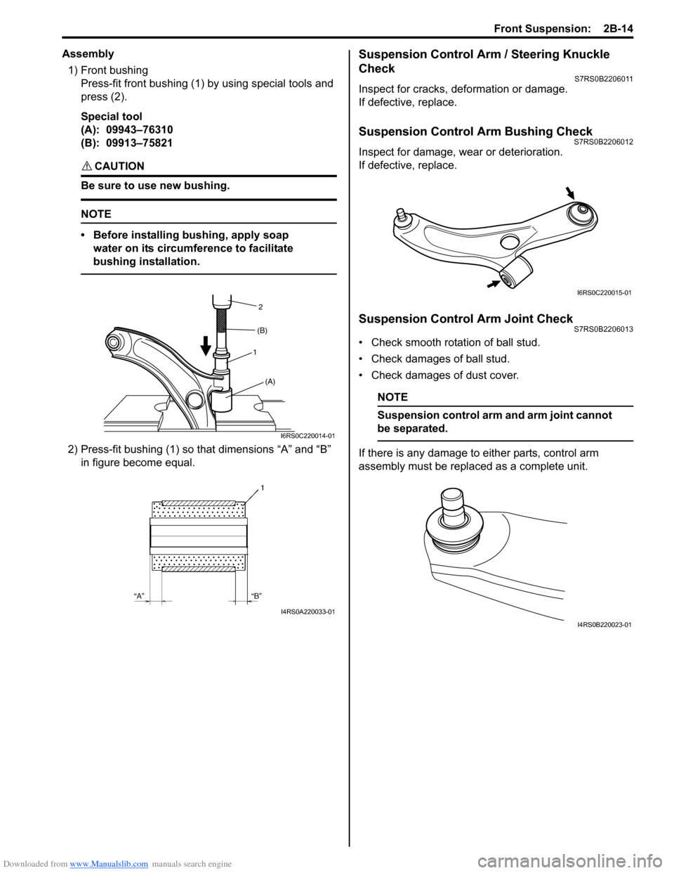
Assembly1) Front bushing Press-fit front bushing (1) by using special tools and
press (2).
Special tool
(A): 09943–76310
(B): 09913–75821
CAUTION!
Be sure to use new bushing.
NOTE
• Before installing bushing, apply soap water on its circumference to facilitate
bushing installation.
2) Press-fit bushing (1) so that dimensions “A” and “B” in figure become equal.
Suspension Control Arm / Steering Knuckle
Check
S7RS0B2206011
Inspect for cracks, deformation or damage.
If defective, replace.
Suspension Control Arm Bushing CheckS7RS0B2206012
Inspect for damage, wear or deterioration.
If defective, replace.
Suspension Control Arm Joint CheckS7RS0B2206013
• Check smooth rotation of ball stud.
• Check damages of ball stud.
• Check damages of dust cover.
NOTE
Suspension control a rm and arm joint cannot
be separated.
If there is any damage to either parts, control arm
assembly must be replaced as a complete unit.
1 2
(A)
(B)
I6RS0C220014-01
I4RS0A220033-01
I6RS0C220015-01
I4RS0B220023-01
Page 448 of 1496
Downloaded from www.Manualslib.com manuals search engine 2B-15 Front Suspension:
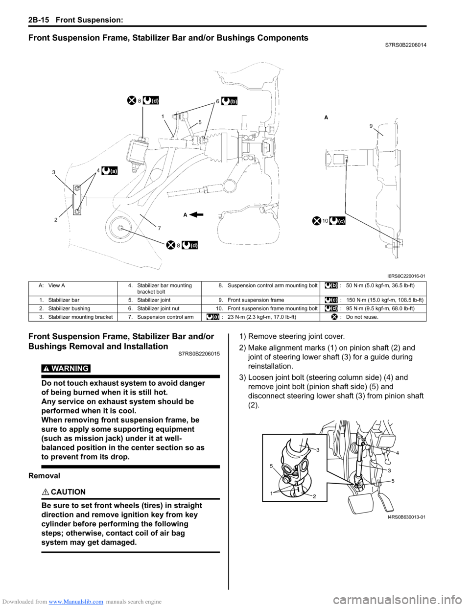
Front Suspension Frame, Stabilizer Bar and/or Bushings ComponentsS7RS0B2206014
Front Suspension Frame, Stabilizer Bar and/or
Bushings Removal and Installation
S7RS0B2206015
WARNING!
Do not touch exhaust system to avoid danger
of being burned when it is still hot.
Any service on exhaust system should be
performed when it is cool.
When removing front suspension frame, be
sure to apply some supporting equipment
(such as mission jack) under it at well-
balanced position in the center section so as
to prevent from its drop.
Removal
CAUTION!
Be sure to set front wheels (tires) in straight
direction and remove ignition key from key
cylinder before performing the following
steps; otherwise, contact coil of air bag
system may get damaged.
1) Remove steering joint cover.
2) Make alignment marks (1) on pinion shaft (2) and joint of steering lower shaft (3) for a guide during
reinstallation.
3) Loosen joint bolt (steering column side) (4) and remove joint bolt (pin ion shaft side) (5) and
disconnect steering lower shaft (3) from pinion shaft
(2).
I6RS0C220016-01
A: View A 4. Stabilizer bar mounting
bracket bolt 8. Suspension control arm mounting bolt : 50 N
⋅m (5.0 kgf-m, 36.5 lb-ft)
1. Stabilizer bar 5. Stabilizer joint 9. Front suspension frame : 150 N⋅m (15.0 kgf-m, 108.5 lb-ft)
2. Stabilizer bushing 6. Stabilizer joint nut10. Front suspension frame mounting bolt : 95 N ⋅m (9.5 kgf-m, 68.0 lb-ft)
3. Stabilizer mounting bracket 7. Suspension control arm : 23 N⋅m (2.3 kgf-m, 17.0 lb-ft) : Do not reuse.
5
2
1
5
34
3
I4RS0B630013-01
Page 452 of 1496
Downloaded from www.Manualslib.com manuals search engine 2B-19 Front Suspension:
13) Install suspension control arm referring to
“Suspension Control Arm / Bushing Removal and
Installation”.
14) Connect couplers of torque sensor and P/S motor.
15) Connect tie-rod ends to knuckles (right & left) and then install cotter pins referring to “Tie-Rod End
Removal and Installa tion in Section 6C”.
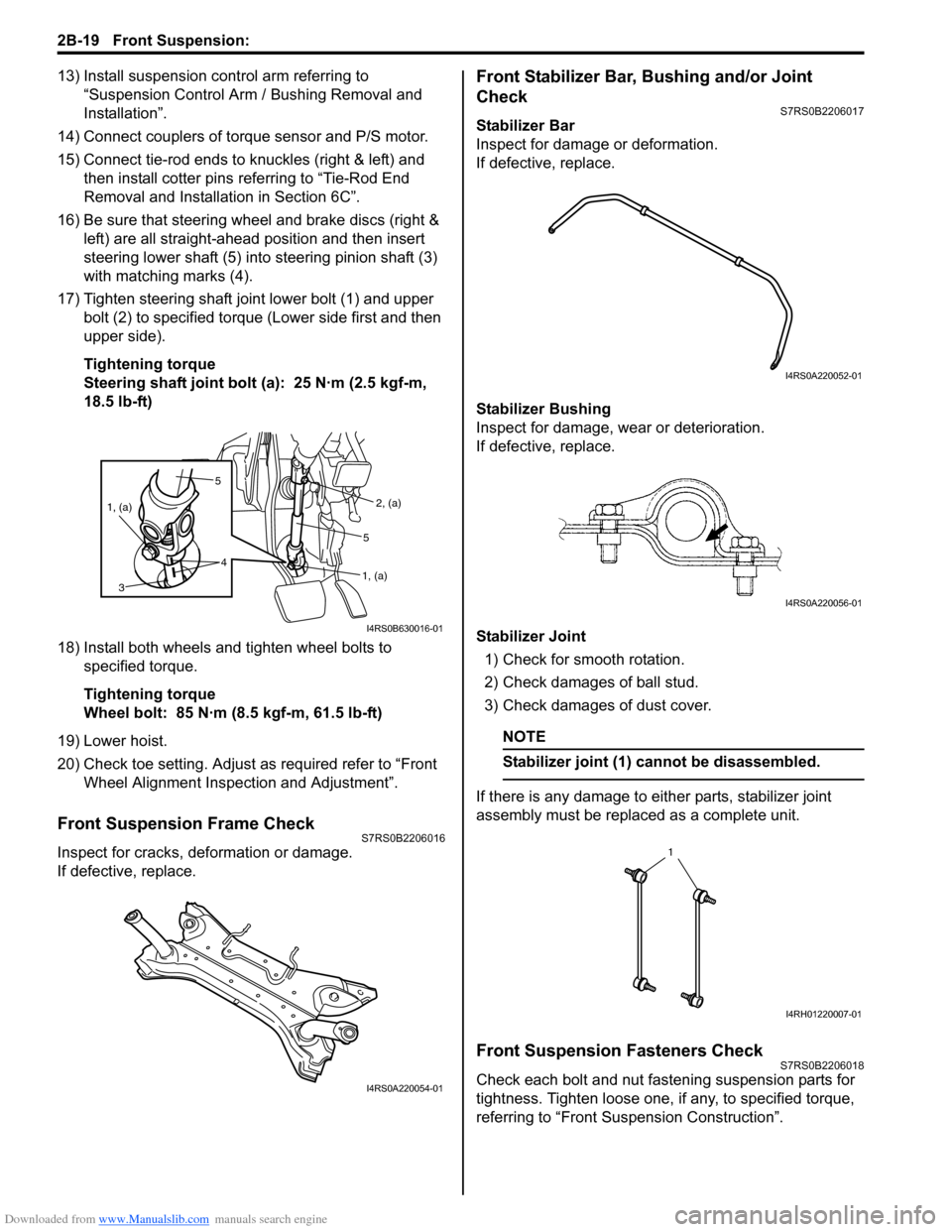
16) Be sure that steering wheel and brake discs (right & left) are all straight-ahead position and then insert
steering lower shaft (5) into steering pinion shaft (3)
with matching marks (4).
17) Tighten steering shaft joint lower bolt (1) and upper bolt (2) to specified torque (Lower side first and then
upper side).
Tightening torque
Steering shaft joint bolt (a): 25 N·m (2.5 kgf-m,
18.5 lb-ft)
18) Install both wheels and tighten wheel bolts to specified torque.
Tightening torque
Wheel bolt: 85 N·m (8.5 kgf-m, 61.5 lb-ft)
19) Lower hoist.
20) Check toe setting. Adjust as required refer to “Front Wheel Alignment Inspection and Adjustment”.
Front Suspension Frame CheckS7RS0B2206016
Inspect for cracks, deformation or damage.
If defective, replace.
Front Stabilizer Bar, Bushing and/or Joint
Check
S7RS0B2206017
Stabilizer Bar
Inspect for damage or deformation.
If defective, replace.
Stabilizer Bushing
Inspect for damage, wear or deterioration.
If defective, replace.
Stabilizer Joint
1) Check for smooth rotation.
2) Check damages of ball stud.
3) Check damages of dust cover.
NOTE
Stabilizer joint (1) cannot be disassembled.
If there is any damage to either parts, stabilizer joint
assembly must be replaced as a complete unit.
Front Suspension Fasteners CheckS7RS0B2206018
Check each bolt and nut fastening suspension parts for
tightness. Tighten loose one, if any, to specified torque,
referring to “Front Suspension Construction”.
5
4
1, (a)
3
2, (a)
1, (a)
5
I4RS0B630016-01
I4RS0A220054-01
I4RS0A220052-01
I4RS0A220056-01
1
I4RH01220007-01
Page 461 of 1496
Downloaded from www.Manualslib.com manuals search engine Rear Suspension: 2C-7
3) Remove rear brake caliper assemblies (right & left)
and brake discs (right & left ). For details, refer to
Step 2) to 3) of “Removal” under “Rear Brake Disc
Removal and Installa tion in Section 4C”.
4) Remove rear wheel hubs (r ight & left). For details,
refer to Step 3) to 5) of “Removal” under “Rear
Wheel Hub Removal and Installation”.
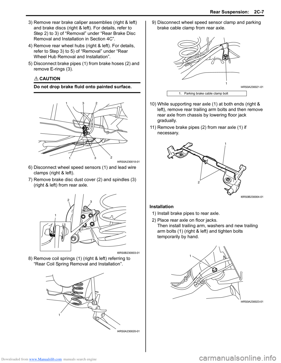
5) Disconnect brake pipes (1) from brake hoses (2) and remove E-rings (3).
CAUTION!
Do not drop brake fluid onto painted surface.
6) Disconnect wheel speed sensors (1) and lead wire clamps (right & left).
7) Remove brake disc dust cover (2) and spindles (3) (right & left) from rear axle.
8) Remove coil springs (1) (right & left) referring to “Rear Coil Spring Removal and Installation”. 9) Disconnect wheel speed sensor clamp and parking
brake cable clamp from rear axle.
10) While supporting rear axle (1) at both ends (right & left), remove rear trailing arm bolts and then remove
rear axle from chassis by lowering floor jack
gradually.
11) Remove brake pipes (2) from rear axle (1) if necessary.
Installation 1) Install brake pipes to rear axle.
2) Place rear axle on floor jacks. Then install trailing arm, washers and new trailing
arm bolts (1) (right & left) and tighten bolts
temporarily by hand.
1
1
2
2
3
3I4RS0A230018-01
1
2
3
I6RS0B230003-01
1
I4RS0A230020-01
1. Parking brake cable clamp bolt
1I4RS0A230021-01
2
1
I6RS0B230004-01
1
I4RS0A230023-01