all SUZUKI SWIFT 2008 2.G Service Workshop Manual
[x] Cancel search | Manufacturer: SUZUKI, Model Year: 2008, Model line: SWIFT, Model: SUZUKI SWIFT 2008 2.GPages: 1496, PDF Size: 34.44 MB
Page 1398 of 1496
![SUZUKI SWIFT 2008 2.G Service Workshop Manual Downloaded from www.Manualslib.com manuals search engine 9M-1 Exterior Trim:
Body, Cab and Accessories
Exterior Trim
Repair Instructions
Roof Molding ComponentsS7RS0B9D06001
42
2
1
3
[A]
2
53 mm (2.0](/img/20/7607/w960_7607-1397.png "SUZUKI SWIFT 2008 2.G Service Workshop Manual Downloaded from www.Manualslib.com manuals search engine 9M-1 Exterior Trim:
Body, Cab and Accessories
Exterior Trim
Repair Instructions
Roof Molding ComponentsS7RS0B9D06001
42
2
1
3
[A]
2
53 mm (2.0")
Downloaded from www.Manualslib.com manuals search engine 9M-1 Exterior Trim:
Body, Cab and Accessories
Exterior Trim
Repair Instructions
Roof Molding ComponentsS7RS0B9D06001
42
2
1
3
[A]
2
53 mm (2.09 in.)
I6RS0C9D0001-01
[A]: Roof side weather-strip installation position
3. Roof molding clip (Push-in type)
: Install roof molding clip to specified position on body with epoxy adhesive applied.
1. Roof molding 4. Windshield side garnish
2. Roof side weather-strip
Page 1401 of 1496
Downloaded from www.Manualslib.com manuals search engine Table of Contents 10- i
10
Section 10
CONTENTS
Control Systems
Precautions ............................................... 10-1
Precautions........................................................... 10-1
Precautions for Control Systems......................... 10-1
Body Electrical Contro l System ........... 10B-1
Precautions......................................................... 10B-1
Precautions in Diagnosing Trouble ................... 10B-1
General Description ........................................... 10B-1 BCM General Description ................................. 10B-1
CAN Communication System Description......... 10B-2
Theft Deterrent Light ......................................... 10B-3
Security Alarm Description (If Equipped) .......... 10B-3
Schematic and Routing Diagram ...................... 10B-4 Body Electrical Control System Wiring Circuit Diagram .......................................................... 10B-4
Connector Layout Diagram of BCM and Junction Block Assembly ................................ 10B-7
Component Locatio n ......................................... 10B-8
BCM and Related System Component Location .......................................................... 10B-8
Diagnostic Information an d Procedures .......... 10B-9
BCM Self-Diagnosis Function ........................... 10B-9
Body Electrical Control System Check............ 10B-10
Scan Tool Data ............................................... 10B-12
DTC Table ....................................................... 10B-14
DTC Check ..................................................... 10B-14
DTC Clearance ............................................... 10B-15
BCM Power Circuit and Ground Circuit Check 10B-16
DTC B1133 (DTC No. 1133): Battery Voltage Too High ....................................................... 10B-17
DTC B1141 / DTC B1142 (No. 1141 / No. 1142): Outside Air Temperature (Ambient
Temp.) Sensor Circuit Ma lfunction ................ 10B-18
DTC B1150 (No. 1150): Air Bag Communication Circuit Malfunction .............. 10B-19
DTC B1157 (No. 1157): Air Bag Deployment Signal Input ................................................... 10B-20
DTC B1170 (No. 1170 ): EEPROM Access
Error .............................................................. 10B-21
DTC U0155 (No. 0155): Lost Communication with Instrument Panel Cluster (IPC) Control
Module .......................................................... 10B-21
DTC U1073 (No. 1073): Control Module Communication Bus Off ................................ 10B-24 DTC U1100 (No. 1100): Lost Communication
with ECM ....................................................... 10B-25
DTC U1101 (No. 1101): Lost Communication with TCM ....................................................... 10B-27
DTC U1144 (No. 1144): Lost Communication with Keyless Start Control Module ................ 10B-29
Inspection of BCM and its Circuits .................. 10B-31
Repair Instructions ........... ...............................10B-39
BCM (Included in Junction Block Assembly) Removal and Installation ............................... 10B-39
Outside Air Temperature Sensor Removal and Installation .............................................. 10B-39
Outside Air Temperature Sensor Inspection ... 10B-39
Security Alarm Mode Selection Procedure (If Equipped) ...................................................... 10B-39
Special Tools and Equipmen t .........................10B-40
Special Tool .................................................... 10B-40
Immobilizer Control Syst em ................. 10C-1
Precautions.........................................................10C-1
Precautions in Diagnosing Troubles .................10C-1
Precaution in Replacing ECM ...........................10C-1
Precautions in Handli ng Immobilizer Control
System ............................................................10C-1
General Description ...........................................10C-2 Immobilizer Control System Introduction ..........10C-2
Immobilizer Control System Components Location...........................................................10C-3
On-Board Diagnostic System Description (Self-diagnosis Function) ................................10C-3
Schematic and Routing Diag ram ......................10C-4
Immobilizer Control System Wiring Circuit Diagram...........................................................10C-4
Diagnostic Information an d Procedures ..........10C-5
Immobilizer Control System Check ...................10C-5
Diagnostic Trouble Code (DTC) Check.............10C-5
Diagnostic Trouble Code (DTC) Clearance ......10C-6
Diagnostic Trouble Code (DTC) Table ..............10C-6
Scan Tool Data .................................................10C-7
Immobilizer Indicator Lamp Does Not Come ON with Ignition Switch ON and Engine Stop ..10C-7
Immobilizer Indicator Lamp Remains ON after Engine Starts...................................................10C-8
DTC P1614: Transponder Re sponse Error .......10C-9
Page 1402 of 1496
Downloaded from www.Manualslib.com manuals search engine 10-ii Table of Contents
DTC P1615: ID Code Does Not Registered (Vehicle equipped with keyless start system
only) ................................................................10C-9
DTC P1616: Different Registration ID Codes (Vehicle equipped with keyless start system
only) ..............................................................10C-10
DTC P1618: CAN Communication Error (Reception Error for Keyless Start Control
Module) (Vehicle equipped with keyless
start system only) ..........................................10C-11
DTC P1621: Immobilizer Communication Line Error ......................................................10C-12
DTC P1622: EEPROM Reading / Writing Error ..............................................................10C-13
DTC P1623: Unregistered Transponder .........10C-13
DTC P1625: Immobilizer An tenna Error..........10C-14
DTC P1636: Immobilizer Information Registration Failure .......................................10C-14
DTC P1638: Immobilizer Information Mismatched ...................................................10C-15
Inspection of Immobilizer Control Module (ICM) and Its Circuit ....... ...............................10C-16
Repair Instructions ........... ...............................10C-18
Immobilizer Control Mo dule (ICM) Removal
and Installation ..............................................10C-18
Registration of the Ignition Key .......................10C-18
Procedure after ECM Replacement ................10C-18
Special Tools and Equipmen t .........................10C-19
Special Tool ....................................................10C-19
Keyless Start System ....... ......................10E-1
General Description ........................................... 10E-1
Keyless Start System Description ..................... 10E-1
Parts and Functions .......................................... 10E-2
Keyless Engine Start Function .......................... 10E-3
Door Lock Function of Keyless Start System .... 10E-4
Operation Area of Remote Controller................ 10E-5
Alarm Function .................................................. 10E-6
CAN Communication System Description......... 10E-6
Schematic and Routing Diagram ...................... 10E-7 Keyless Start System El ectric Wiring Circuit
Diagram .......................................................... 10E-7
Diagnostic Information and Procedures .......... 10E-8 Precautions in Diagnosing Troubles ................. 10E-8
Self-Diagnosis Function .................................... 10E-8
Keyless Start System Diagn osis Introduction ... 10E-8 Keyless Start System Chec
k ............................. 10E-8
Customer Questionnaire (E xample) .................. 10E-9
Key Indicator Lamp Check .............................. 10E-10
DTC Check...................................................... 10E-10
DTC Table ....................................................... 10E-11
DTC Clearance ............................................... 10E-12
Keyless Start System Symp tom Diagnosis ..... 10E-12
Keyless Start System Operation Inspection .... 10E-13
Door Lock Operation (Keyless Start System) . 10E-14
Inspection of Keyless Start Control Module and Its Circuits .............................................. 10E-14
No DTC Detection After Performing DTC Check ............................................................ 10E-18
Key Indicator Lamp Circuit Check (Key indicator lamp doesn’t light when ignition
knob switch is pushed.) ................................. 10E-20
Keyless Start Control Module Power and Ground Circuit Check .................................... 10E-22
DTC No. 11: Communi cation Error with
Steering Lock Unit ......................................... 10E-23
DTC No. 13 / No. 14: Release Signal Error from Steering Lock Unit / Steering Lock Unit
Malfunction .................................................... 10E-24
DTC No. 21 / No. 22: Internal Error of Keyless Start Control Module (EEPROM reading
error) / (EEPROM writing error) ............ ........ 10E-24
DTC No. 31: Lost Commun ication with BCM .. 10E-25
DTC No. 33: Control Module Communication
Bus Off .......................................................... 10E-27
DTC No. 51 / No. 52 / No. 53: Driver Side / Passenger Side / Rear End Door Request
Switch Failure................................................ 10E-28
Repair Instructions ............ .............................. 10E-30
Antennas and Request Switches Removal and Installation .............................................. 10E-30
Front Door (Driver and Passenger Side), Rear End Door Request Switch Inspection............ 10E-31
Steering Lock Unit Removal and Installation .. 10E-31
Steering Lock Unit Inspection ......................... 10E-31
Front Door Lock Switch In spection ................. 10E-31
Keyless Start Control Module Removal and Installation ..................................................... 10E-32
Remote Controller Inspection.......................... 10E-32
Replacement of Remote Controller Battery .... 10E-32
Registration Procedure for Remote Controller
ID Code ......................................................... 10E-33
Page 1418 of 1496
Downloaded from www.Manualslib.com manuals search engine 10B-15 Body Electrical Control System:
Without Using SUZUKI Scan Tool1) Turn ignition switch to OFF position.
2) Perform following Steps a) to d) within 10 seconds af ter ignition switch is turned ON and engine stops.
a) Turn headlight switch to “SMALL” position.
b) Turn headlight switch to “OFF” position.
c) Repeat Steps a) and b) 2 times.
d) Press and release driver side door switch 3 times.
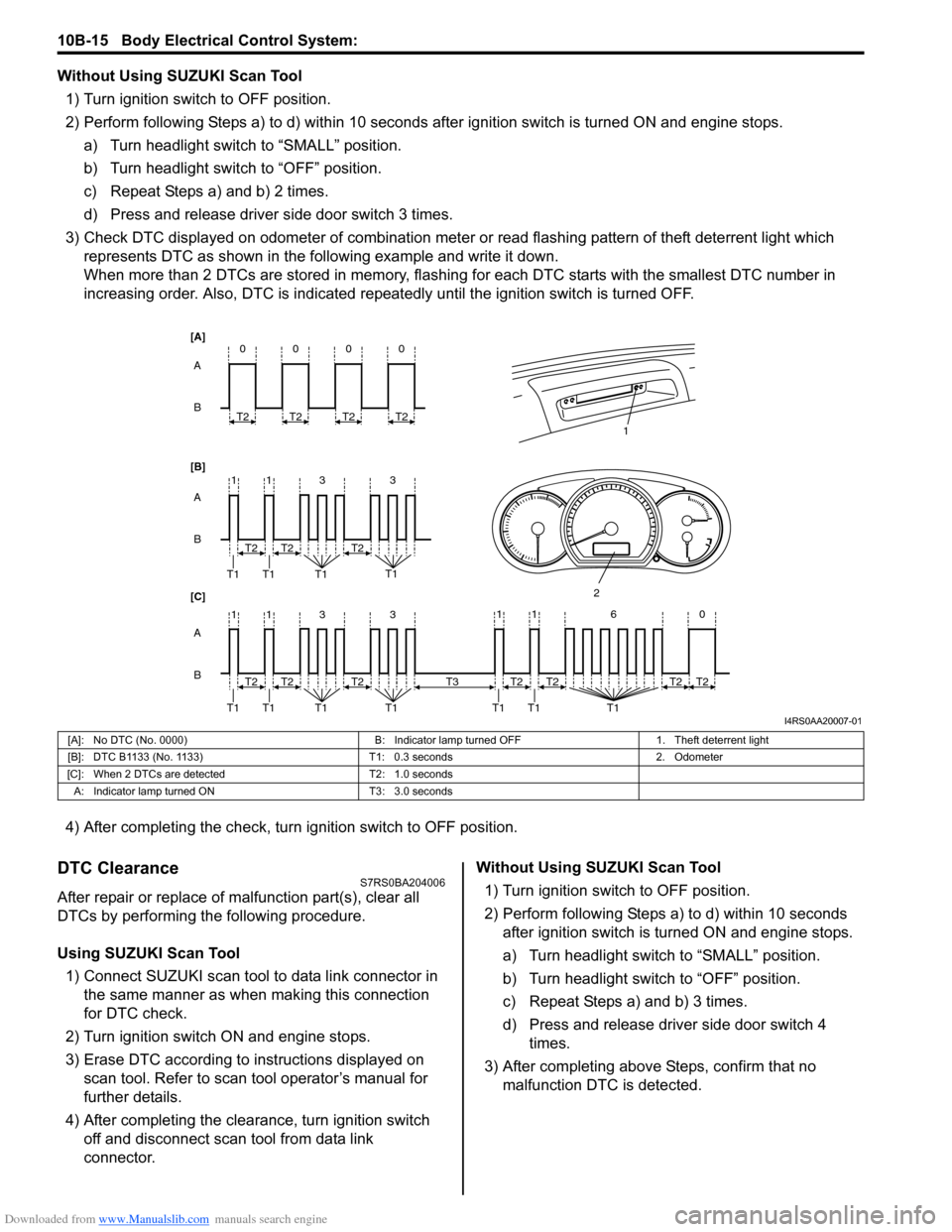
3) Check DTC displayed on odometer of combination meter or read flashing pattern of theft deterrent light which
represents DTC as shown in the following example and write it down.
When more than 2 DTCs are stored in memory, flashing for each DTC starts with the smallest DTC number in
increasing order. Also, DTC is indicated repeatedly until the ignition switch is turned OFF.
4) After completing the check, turn ignition switch to OFF position.
DTC ClearanceS7RS0BA204006
After repair or replace of malfunction part(s), clear all
DTCs by performing the following procedure.
Using SUZUKI Scan Tool 1) Connect SUZUKI scan tool to data link connector in the same manner as when making this connection
for DTC check.
2) Turn ignition switch ON and engine stops.
3) Erase DTC according to instructions displayed on scan tool. Refer to scan tool operator’s manual for
further details.
4) After completing the clear ance, turn ignition switch
off and disconnect scan tool from data link
connector. Without Using SUZUKI Scan Tool
1) Turn ignition switch to OFF position.
2) Perform following Steps a) to d) within 10 seconds after ignition switch is turned ON and engine stops.
a) Turn headlight switch to “SMALL” position.
b) Turn headlight switch to “OFF” position.
c) Repeat Steps a) and b) 3 times.
d) Press and release driver side door switch 4 times.
3) After completing above Steps, confirm that no malfunction DTC is detected.
B A
[B] [A]
[C]
B A B A
3
113
3
113
T2
T1 T1 T1 T1
1
2
T2T2
T2
T1 T1 T1 T1T2T2
0
T2
0
T2
0
T2
0
T2
11 6 0
T1 T1 T1
T2
T3T2T2T2
I4RS0AA20007-01
[A]: No DTC (No. 0000) B: Indicator lamp turned OFF1. Theft deterrent light
[B]: DTC B1133 (No. 1133) T1: 0.3 seconds2. Odometer
[C]: When 2 DTCs are detected T2: 1.0 seconds
A: Indicator lamp tur ned ON T3: 3.0 seconds
Page 1423 of 1496
Downloaded from www.Manualslib.com manuals search engine Body Electrical Control System: 10B-20
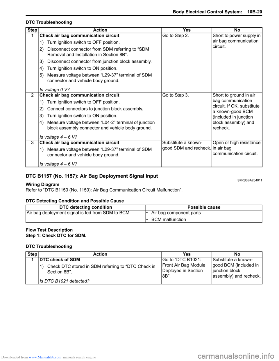
DTC Troubleshooting
DTC B1157 (No. 1157): Air Bag Deployment Signal InputS7RS0BA204011
Wiring Diagram
Refer to “DTC B1150 (No. 1150): Air Bag Communication Circuit Malfunction”.
DTC Detecting Conditi on and Possible Cause
Flow Test Description
Step 1: Check DTC for SDM.
DTC Troubleshooting Step Action Yes No
1 Check air bag communication circuit
1) Turn ignition switch to OFF position.
2) Disconnect connector from SDM referring to “SDM
Removal and Installation in Section 8B”.
3) Disconnect connector from junction block assembly.
4) Turn ignition switch to ON position.
5) Measure voltage between “L29-37” terminal of SDM connector and vehicle body ground.
Is voltage 0 V? Go to Step 2. Short to power supply in
air bag communication
circuit.
2 Check air bag communication circuit
1) Turn ignition switch to OFF position.
2) Connect connectors to junction block assembly.
3) Turn ignition switch to ON position.
4) Measure voltage between “L04-2” terminal of junction
block assembly connector and vehicle body ground.
Is voltage 4 – 6 V? Go to Step 3.
Short to ground in air
bag communication
circuit. If OK, substitute
a known-good BCM
(included in junction
block assembly) and
recheck.
3 Check air bag communication circuit
1) Measure voltage between “L29-37” terminal of SDM
connector and vehicle body ground.
Is voltage 4 – 6 V? Substitute a known-
good SDM and recheck.
Open or high resistance
in air bag
communication circuit.
DTC detecting condition
Possible cause
Air bag deployment signal is fed from SDM to BCM. • Air bag component parts
• BCM malfunction
StepAction YesNo
1 DTC check of SDM
1) Check DTC stored in SDM re ferring to “DTC Check in
Section 8B”.
Is DTC B1021 detected? Go to “DTC B1021:
Front Air Bag Module
Deployed in Section
8B”.
Substitute a known-
good BCM (included in
junction block
assembly) and recheck.
Page 1426 of 1496
Downloaded from www.Manualslib.com manuals search engine 10B-23 Body Electrical Control System:
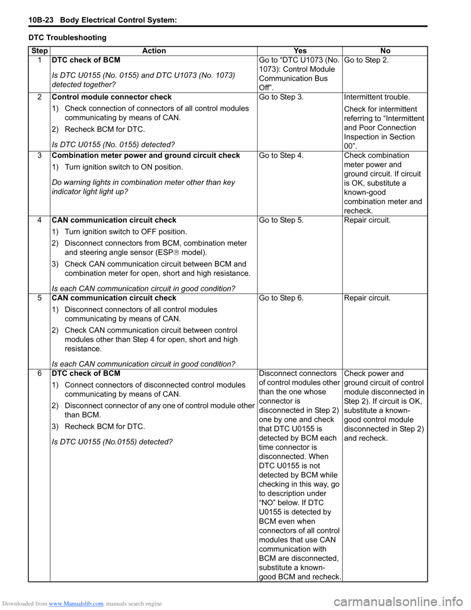
DTC TroubleshootingStep Action YesNo
1 DTC check of BCM
Is DTC U0155 (No. 0155) and DTC U1073 (No. 1073)
detected together? Go to “DTC U1073 (No.
1073): Control Module
Communication Bus
Off”.Go to Step 2.
2 Control module connector check
1) Check connection of connectors of all control modules
communicating by means of CAN.
2) Recheck BCM for DTC.
Is DTC U0155 (No. 0155) detected? Go to Step 3.
Intermittent trouble.
Check for intermittent
referring to “Intermittent
and Poor Connection
Inspection in Section
00”.
3 Combination meter power and ground circuit check
1) Turn ignition switch to ON position.
Do warning lights in combi nation meter other than key
indicator light light up? Go to Step 4.
Check combination
meter power and
ground circuit. If circuit
is OK, substitute a
known-good
combination meter and
recheck.
4 CAN communication circuit check
1) Turn ignition switch to OFF position.
2) Disconnect connectors from BCM, combination meter
and steering angle sensor (ESP ® model).
3) Check CAN communication circuit between BCM and combination meter for open, short and high resistance.
Is each CAN communication circuit in good condition? Go to Step 5.
Repair circuit.
5 CAN communication circuit check
1) Disconnect connectors of all control modules
communicating by means of CAN.
2) Check CAN communication circuit between control modules other than Step 4 for open, short and high
resistance.
Is each CAN communication circuit in good condition? Go to Step 6.
Repair circuit.
6 DTC check of BCM
1) Connect connectors of disconnected control modules
communicating by means of CAN.
2) Disconnect connector of any one of control module other than BCM.
3) Recheck BCM for DTC.
Is DTC U0155 (No.0155) detected? Disconnect connectors
of control modules other
than the one whose
connector is
disconnected in Step 2)
one by one and check
that DTC U0155 is
detected by BCM each
time connector is
disconnected. When
DTC U0155 is not
detected by BCM while
checking in this way, go
to description under
“NO” below. If DTC
U0155 is detected by
BCM even when
connectors of all control
modules that use CAN
communication with
BCM are disconnected,
substitute a known-
good BCM and recheck.Check power and
ground circuit of control
module disconnected in
Step 2). If circuit is OK,
substitute a known-
good control module
disconnected in Step 2)
and recheck.
Page 1427 of 1496
Downloaded from www.Manualslib.com manuals search engine Body Electrical Control System: 10B-24
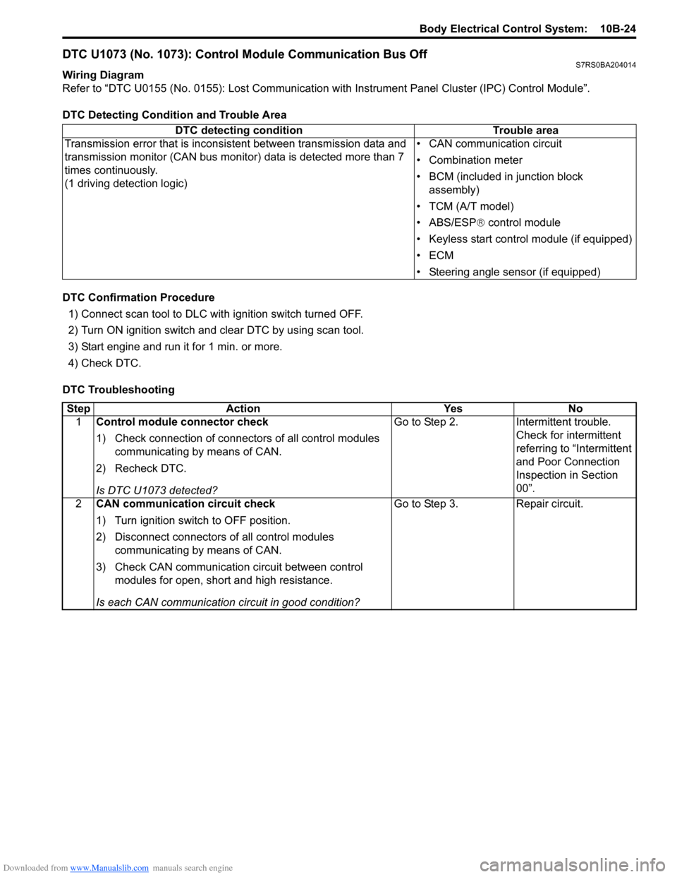
DTC U1073 (No. 1073): Control Module Communication Bus OffS7RS0BA204014
Wiring Diagram
Refer to “DTC U0155 (No. 0155): Lost Communication with Instrument Panel Cluster (IPC) Control Module”.
DTC Detecting Condition and Trouble Area
DTC Confirmation Procedure 1) Connect scan tool to DLC with ignition switch turned OFF.
2) Turn ON ignition switch and clear DTC by using scan tool.
3) Start engine and run it for 1 min. or more.
4) Check DTC.
DTC Troubleshooting DTC detecting condition Trouble area
Transmission error that is inconsistent between transmission data and
transmission monitor (CAN bus monitor) data is detected more than 7
times continuously.
(1 driving detection logic) • CAN communication circuit
• Combination meter
• BCM (included in junction block
assembly)
• TCM (A/T model)
• ABS/ESP ® control module
• Keyless start control module (if equipped)
•ECM
• Steering angle sensor (if equipped)
Step Action YesNo
1 Control module connector check
1) Check connection of connectors of all control modules
communicating by means of CAN.
2) Recheck DTC.
Is DTC U1073 detected? Go to Step 2.
Intermittent trouble.
Check for intermittent
referring to “Intermittent
and Poor Connection
Inspection in Section
00”.
2 CAN communication circuit check
1) Turn ignition switch to OFF position.
2) Disconnect connectors of all control modules
communicating by means of CAN.
3) Check CAN communication circuit between control modules for open, short and high resistance.
Is each CAN communication circuit in good condition? Go to Step 3.
Repair circuit.
Page 1428 of 1496
Downloaded from www.Manualslib.com manuals search engine 10B-25 Body Electrical Control System:
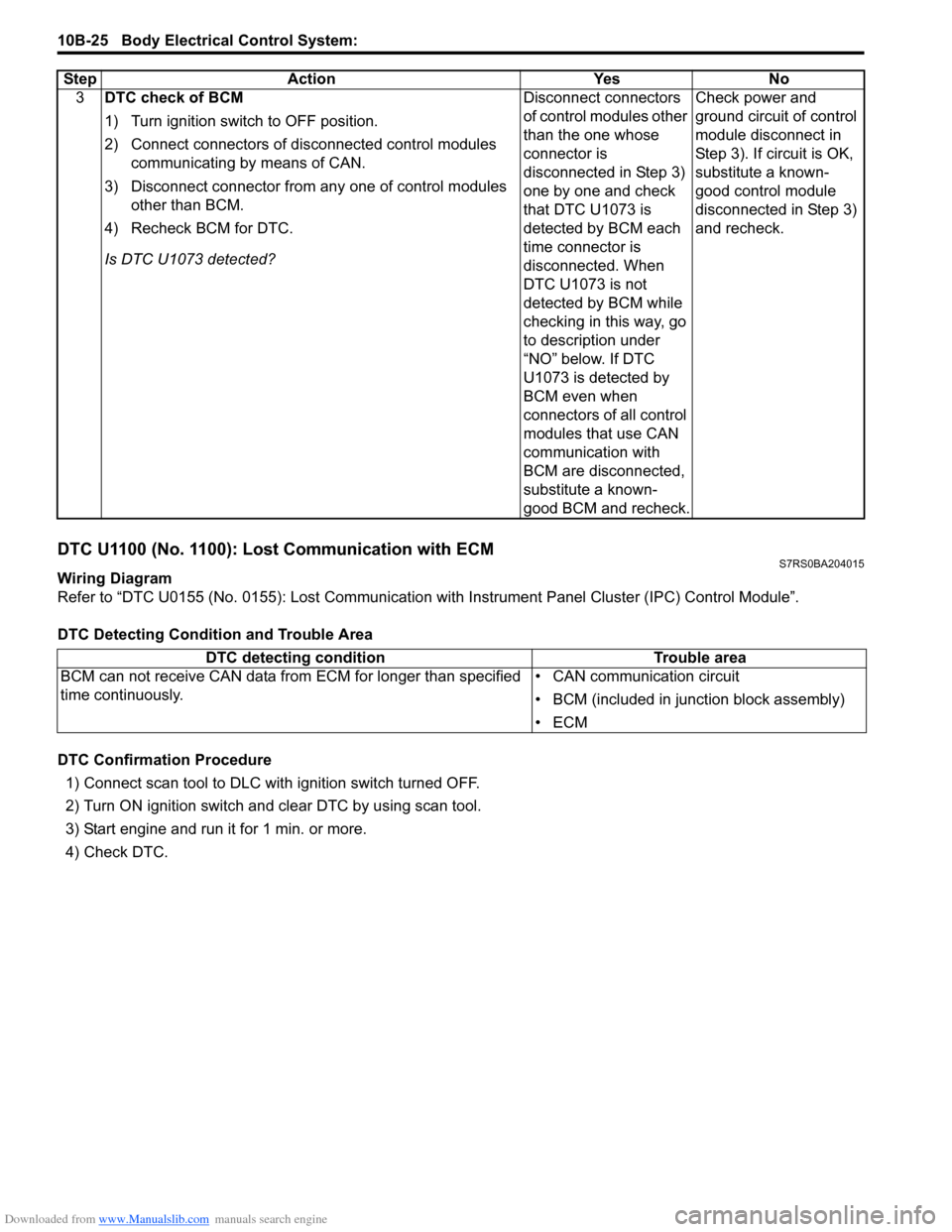
DTC U1100 (No. 1100): Lost Communication with ECMS7RS0BA204015
Wiring Diagram
Refer to “DTC U0155 (No. 0155): Lost Communication with Instrument Panel Cluster (IPC) Control Module”.
DTC Detecting Condition and Trouble Area
DTC Confirmation Procedure 1) Connect scan tool to DLC with ignition switch turned OFF.
2) Turn ON ignition switch and clear DTC by using scan tool.
3) Start engine and run it for 1 min. or more.
4) Check DTC. 3
DTC check of BCM
1) Turn ignition switch to OFF position.
2) Connect connectors of disconnected control modules
communicating by means of CAN.
3) Disconnect connector from any one of control modules other than BCM.
4) Recheck BCM for DTC.
Is DTC U1073 detected? Disconnect connectors
of control modules other
than the one whose
connector is
disconnected in Step 3)
one by one and check
that DTC U1073 is
detected by BCM each
time connector is
disconnected. When
DTC U1073 is not
detected by BCM while
checking in this way, go
to description under
“NO” below. If DTC
U1073 is detected by
BCM even when
connectors of all control
modules that use CAN
communication with
BCM are disconnected,
substitute a known-
good BCM and recheck.Check power and
ground circuit of control
module disconnect in
Step 3). If circuit is OK,
substitute a known-
good control module
disconnected in Step 3)
and recheck.
Step Action Yes No
DTC detecting condition
Trouble area
BCM can not receive CAN data from ECM for longer than specified
time continuously. • CAN communication circuit
• BCM (included in junction block assembly)
•ECM
Page 1429 of 1496
Downloaded from www.Manualslib.com manuals search engine Body Electrical Control System: 10B-26
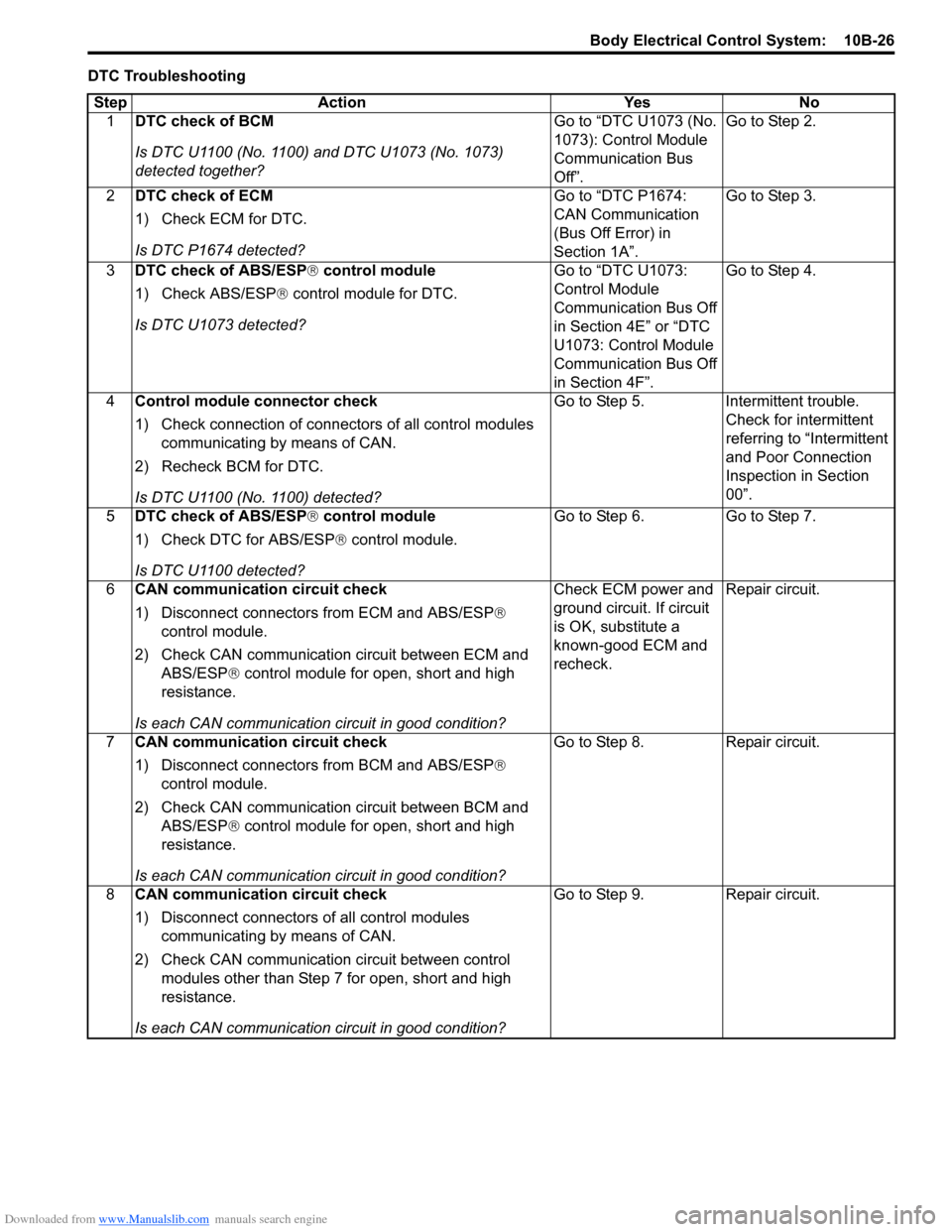
DTC TroubleshootingStep Action Yes No 1 DTC check of BCM
Is DTC U1100 (No. 1100) and DTC U1073 (No. 1073)
detected together? Go to “DTC U1073 (No.
1073): Control Module
Communication Bus
Off”.Go to Step 2.
2 DTC check of ECM
1) Check ECM for DTC.
Is DTC P1674 detected? Go to “DTC P1674:
CAN Communication
(Bus Off Error) in
Section 1A”.Go to Step 3.
3 DTC check of ABS/ESP ® control module
1) Check ABS/ESP ® control module for DTC.
Is DTC U1073 detected? Go to “DTC U1073:
Control Module
Communication Bus Off
in Section 4E” or “DTC
U1073: Control Module
Communication Bus Off
in Section 4F”.Go to Step 4.
4 Control module connector check
1) Check connection of connectors of all control modules
communicating by means of CAN.
2) Recheck BCM for DTC.
Is DTC U1100 (No. 1100) detected? Go to Step 5. Intermittent trouble.
Check for intermittent
referring to “Intermittent
and Poor Connection
Inspection in Section
00”.
5 DTC check of ABS/ESP ® control module
1) Check DTC for ABS/ESP ® control module.
Is DTC U1100 detected? Go to Step 6. Go to Step 7.
6 CAN communication circuit check
1) Disconnect connector s from ECM and ABS/ESP ®
control module.
2) Check CAN communication circuit between ECM and ABS/ESP ® control module for open, short and high
resistance.
Is each CAN communication circuit in good condition? Check ECM power and
ground circuit. If circuit
is OK, substitute a
known-good ECM and
recheck.
Repair circuit.
7 CAN communication circuit check
1) Disconnect connector s from BCM and ABS/ESP ®
control module.
2) Check CAN communication circuit between BCM and ABS/ESP ® control module for open, short and high
resistance.
Is each CAN communication circuit in good condition? Go to Step 8. Repair circuit.
8 CAN communication circuit check
1) Disconnect connectors of all control modules
communicating by means of CAN.
2) Check CAN communication circuit between control modules other than Step 7 for open, short and high
resistance.
Is each CAN communication circuit in good condition? Go to Step 9. Repair circuit.
Page 1430 of 1496
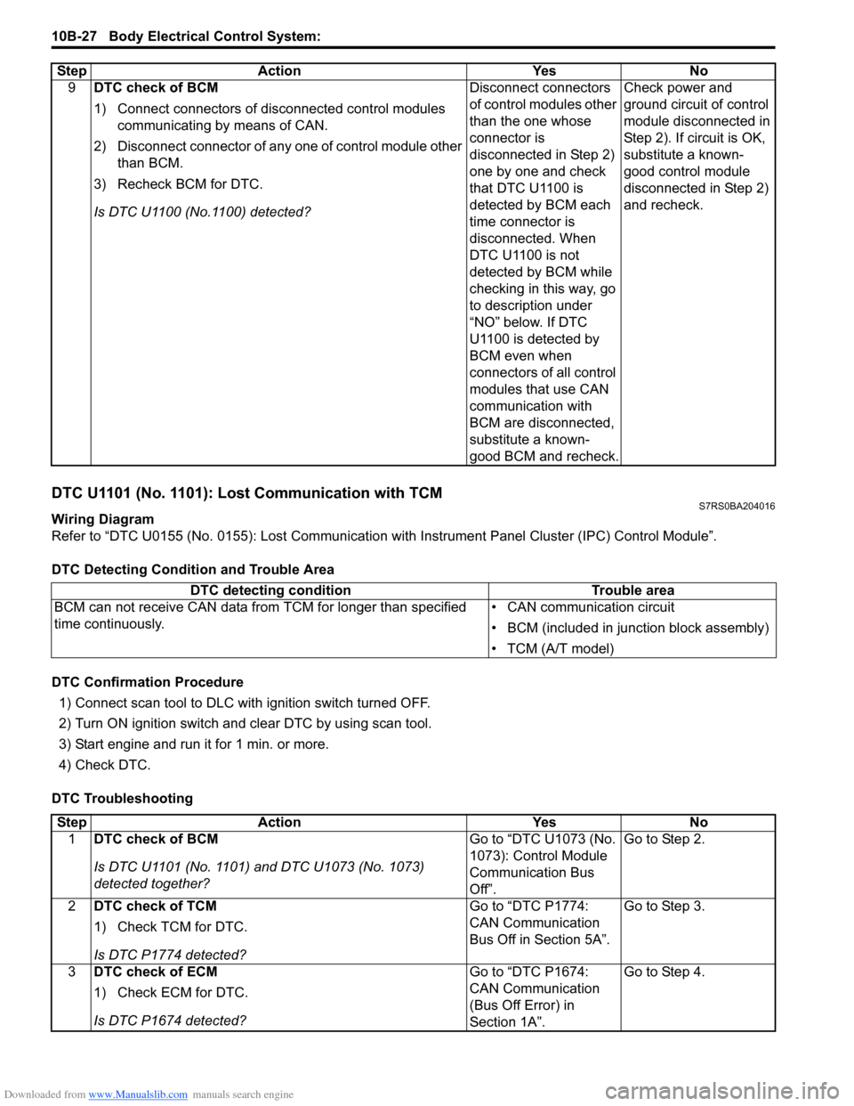
Downloaded from www.Manualslib.com manuals search engine 10B-27 Body Electrical Control System:
DTC U1101 (No. 1101): Lost Communication with TCMS7RS0BA204016
Wiring Diagram
Refer to “DTC U0155 (No. 0155): Lost Communication with Instrument Panel Cluster (IPC) Control Module”.
DTC Detecting Condition and Trouble Area
DTC Confirmation Procedure 1) Connect scan tool to DLC with ignition switch turned OFF.
2) Turn ON ignition switch and clear DTC by using scan tool.
3) Start engine and run it for 1 min. or more.
4) Check DTC.
DTC Troubleshooting 9
DTC check of BCM
1) Connect connectors of disconnected control modules
communicating by means of CAN.
2) Disconnect connector of any one of control module other than BCM.
3) Recheck BCM for DTC.
Is DTC U1100 (No.1100) detected? Disconnect connectors
of control modules other
than the one whose
connector is
disconnected in Step 2)
one by one and check
that DTC U1100 is
detected by BCM each
time connector is
disconnected. When
DTC U1100 is not
detected by BCM while
checking in this way, go
to description under
“NO” below. If DTC
U1100 is detected by
BCM even when
connectors of all control
modules that use CAN
communication with
BCM are disconnected,
substitute a known-
good BCM and recheck.Check power and
ground circuit of control
module disconnected in
Step 2). If circuit is OK,
substitute a known-
good control module
disconnected in Step 2)
and recheck.
Step Action Yes No
DTC detecting condition
Trouble area
BCM can not receive CAN data from TCM for longer than specified
time continuously. • CAN communication circuit
• BCM (included in junction block assembly)
• TCM (A/T model)
Step
Action YesNo
1 DTC check of BCM
Is DTC U1101 (No. 1101) and DTC U1073 (No. 1073)
detected together? Go to “DTC U1073 (No.
1073): Control Module
Communication Bus
Off”.Go to Step 2.
2 DTC check of TCM
1) Check TCM for DTC.
Is DTC P1774 detected? Go to “DTC P1774:
CAN Communication
Bus Off in Section 5A”.
Go to Step 3.
3 DTC check of ECM
1) Check ECM for DTC.
Is DTC P1674 detected? Go to “DTC P1674:
CAN Communication
(Bus Off Error) in
Section 1A”.Go to Step 4.