all SUZUKI SWIFT 2008 2.G Service Workshop Manual
[x] Cancel search | Manufacturer: SUZUKI, Model Year: 2008, Model line: SWIFT, Model: SUZUKI SWIFT 2008 2.GPages: 1496, PDF Size: 34.44 MB
Page 1431 of 1496
Downloaded from www.Manualslib.com manuals search engine Body Electrical Control System: 10B-28
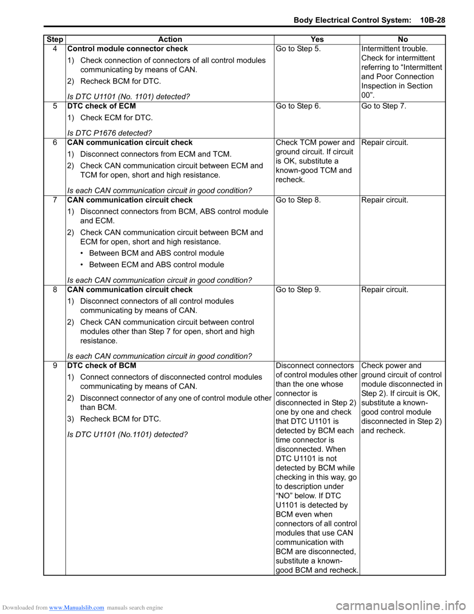
4Control module connector check
1) Check connection of connectors of all control modules
communicating by means of CAN.
2) Recheck BCM for DTC.
Is DTC U1101 (No. 1101) detected? Go to Step 5. Intermittent trouble.
Check for intermittent
referring to “Intermittent
and Poor Connection
Inspection in Section
00”.
5 DTC check of ECM
1) Check ECM for DTC.
Is DTC P1676 detected? Go to Step 6. Go to Step 7.
6 CAN communication circuit check
1) Disconnect connectors from ECM and TCM.
2) Check CAN communication circuit between ECM and
TCM for open, short and high resistance.
Is each CAN communication circuit in good condition? Check TCM power and
ground circuit. If circuit
is OK, substitute a
known-good TCM and
recheck.
Repair circuit.
7 CAN communication circuit check
1) Disconnect connectors from BCM, ABS control module
and ECM.
2) Check CAN communication circuit between BCM and ECM for open, short and high resistance.
• Between BCM and ABS control module
• Between ECM and ABS control module
Is each CAN communication circuit in good condition? Go to Step 8. Repair circuit.
8 CAN communication circuit check
1) Disconnect connectors of all control modules
communicating by means of CAN.
2) Check CAN communication circuit between control modules other than Step 7 for open, short and high
resistance.
Is each CAN communication circuit in good condition? Go to Step 9. Repair circuit.
9 DTC check of BCM
1) Connect connectors of disconnected control modules
communicating by means of CAN.
2) Disconnect connector of any one of control module other than BCM.
3) Recheck BCM for DTC.
Is DTC U1101 (No.1101) detected? Disconnect connectors
of control modules other
than the one whose
connector is
disconnected in Step 2)
one by one and check
that DTC U1101 is
detected by BCM each
time connector is
disconnected. When
DTC U1101 is not
detected by BCM while
checking in this way, go
to description under
“NO” below. If DTC
U1101 is detected by
BCM even when
connectors of all control
modules that use CAN
communication with
BCM are disconnected,
substitute a known-
good BCM and recheck.Check power and
ground circuit of control
module disconnected in
Step 2). If circuit is OK,
substitute a known-
good control module
disconnected in Step 2)
and recheck.
Step Action Yes No
Page 1432 of 1496
Downloaded from www.Manualslib.com manuals search engine 10B-29 Body Electrical Control System:
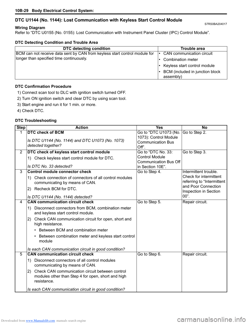
DTC U1144 (No. 1144): Lost Communication with Keyless Start Control ModuleS7RS0BA204017
Wiring Diagram
Refer to “DTC U0155 (No. 0155): Lost Communication with Instrument Panel Cluster (IPC) Control Module”.
DTC Detecting Condition and Trouble Area
DTC Confirmation Procedure 1) Connect scan tool to DLC with ignition switch turned OFF.
2) Turn ON ignition switch and clear DTC by using scan tool.
3) Start engine and run it for 1 min. or more.
4) Check DTC.
DTC Troubleshooting DTC detecting condition Trouble area
BCM can not receive data sent by CAN from keyless start control module for
longer than specified time continuously. • CAN communication circuit
• Combination meter
• Keyless start control module
• BCM (included in junction block
assembly)
Step Action YesNo
1 DTC check of BCM
Is DTC U1144 (No. 1144) and DTC U1073 (No. 1073)
detected together? Go to “DTC U1073 (No.
1073): Control Module
Communication Bus
Off”.Go to Step 2.
2 DTC check of keyless start control module
1) Check keyless start co ntrol module for DTC.
Is DTC No. 33 detected? Go to “DTC No. 33:
Control Module
Communication Bus Off
in Section 10E”.Go to Step 3.
3 Control module connector check
1) Check connection of connectors of all control modules
communicating by means of CAN.
2) Recheck BCM for DTC.
Is DTC U1144 (No. 1144) detected? Go to Step 4.
Intermittent trouble.
Check for intermittent
referring to “Intermittent
and Poor Connection
Inspection in Section
00”.
4 CAN communication circuit check
1) Disconnect connectors from BCM, combination meter
and keyless start control module.
2) Check CAN communication circuit for open, short and high resistance.
• Between BCM and combination meter
• Between combination meter and keyless start control module
Is each CAN communication circuit in good condition? Go to Step 5.
Repair circuit.
5 CAN communication circuit check
1) Disconnect connectors of all control modules
communicating by means of CAN.
2) Check CAN communication circuit between control modules other than Step 4 for open, short and high
resistance.
Is each CAN communication circuit in good condition? Go to Step 6.
Repair circuit.
Page 1433 of 1496
Downloaded from www.Manualslib.com manuals search engine Body Electrical Control System: 10B-30
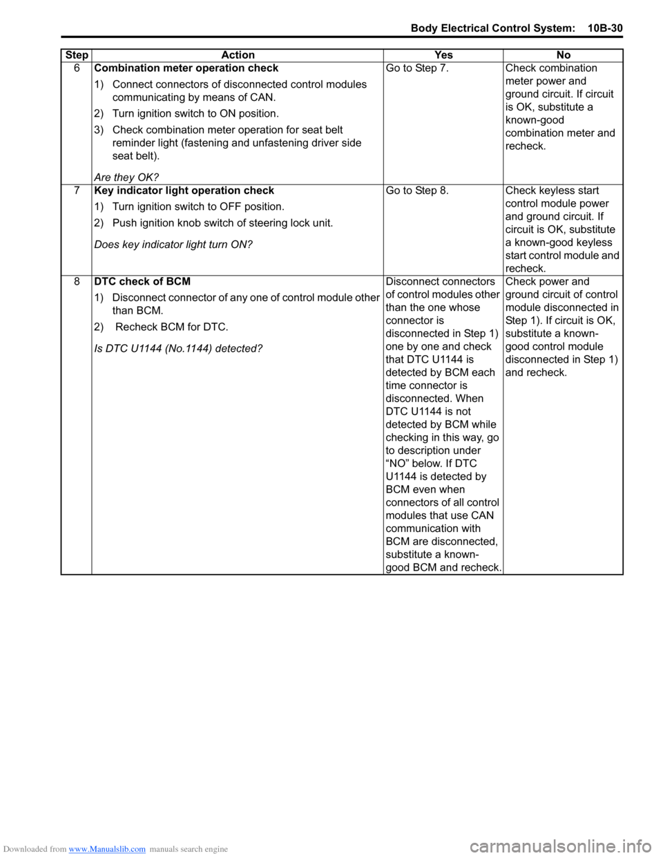
6Combination meter operation check
1) Connect connectors of disconnected control modules
communicating by means of CAN.
2) Turn ignition switch to ON position.
3) Check combination meter operation for seat belt reminder light (fastening and unfastening driver side
seat belt).
Are they OK? Go to Step 7.
Check combination
meter power and
ground circuit. If circuit
is OK, substitute a
known-good
combination meter and
recheck.
7 Key indicator light operation check
1) Turn ignition switch to OFF position.
2) Push ignition knob switch of steering lock unit.
Does key indicator light turn ON? Go to Step 8.
Check keyless start
control module power
and ground circuit. If
circuit is OK, substitute
a known-good keyless
start control module and
recheck.
8 DTC check of BCM
1) Disconnect connector of any one of control module other
than BCM.
2) Recheck BCM for DTC.
Is DTC U1144 (No.1144) detected? Disconnect connectors
of control modules other
than the one whose
connector is
disconnected in Step 1)
one by one and check
that DTC U1144 is
detected by BCM each
time connector is
disconnected. When
DTC U1144 is not
detected by BCM while
checking in this way, go
to description under
“NO” below. If DTC
U1144 is detected by
BCM even when
connectors of all control
modules that use CAN
communication with
BCM are disconnected,
substitute a known-
good BCM and recheck.Check power and
ground circuit of control
module disconnected in
Step 1). If circuit is OK,
substitute a known-
good control module
disconnected in Step 1)
and recheck.
Step
Action YesNo
Page 1434 of 1496
Downloaded from www.Manualslib.com manuals search engine 10B-31 Body Electrical Control System:
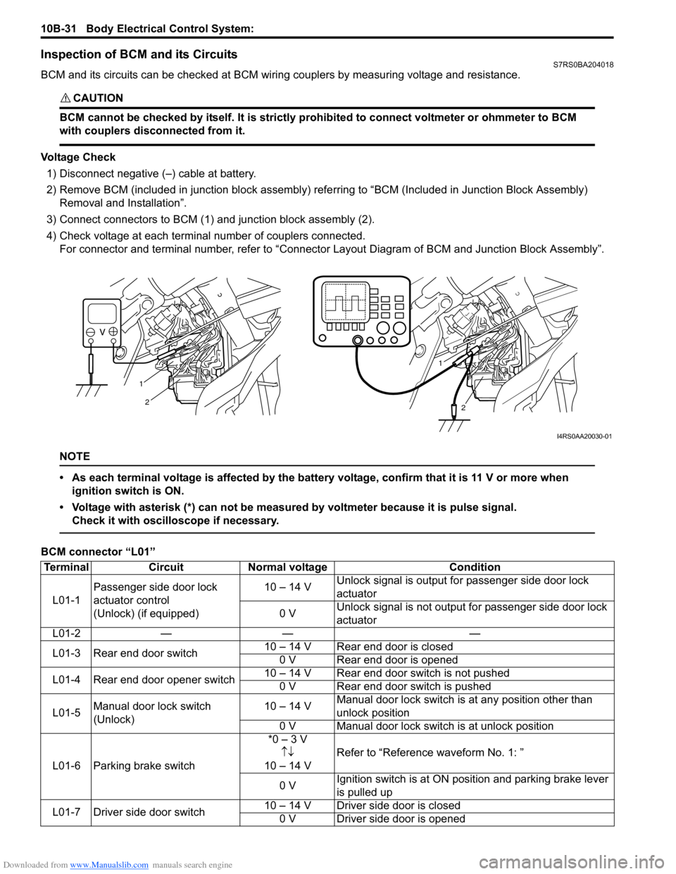
Inspection of BCM and its CircuitsS7RS0BA204018
BCM and its circuits can be checked at BCM wiring couplers by measuring voltage and resistance.
CAUTION!
BCM cannot be checked by itself. It is strictly prohibited to connect voltmeter or ohmmeter to BCM
with couplers disconnected from it.
Voltage Check1) Disconnect negative (–) cable at battery.
2) Remove BCM (included in junction block assembly) refe rring to “BCM (Included in Junction Block Assembly)
Removal and Installation”.
3) Connect connectors to BCM (1) and junction block assembly (2).
4) Check voltage at each terminal number of couplers connected. For connector and terminal number, refer to “Connector Layout Diagram of BCM and Junction Block Assembly”.
NOTE
• As each terminal voltage is affected by the battery voltage, confirm that it is 11 V or more when
ignition switch is ON.
• Voltage with asterisk (*) can not be measured by voltmeter because it is pulse signal. Check it with oscilloscope if necessary.
BCM connector “L01”
1
2
1
2
I4RS0AA20030-01
Terminal CircuitNormal voltage Condition
L01-1 Passenger side door lock
actuator control
(Unlock) (if equipped) 10 – 14 V
Unlock signal is output fo
r passenger side door lock
actuator
0 V Unlock signal is not output for passenger side door lock
actuator
L01-2 — — —
L01-3 Rear end door switch 10 – 14 V Rear end door is closed
0 V Rear end door is opened
L01-4 Rear end door opener switch 10 – 14 V Rear end door switch is not pushed
0 V Rear end door switch is pushed
L01-5 Manual door lock switch
(Unlock) 10 – 14 V
Manual door lock switch is at any position other than
unlock position
0 V Manual door lock switch is at unlock position
L01-6 Parking brake switch *0 – 3 V
↑↓
10 – 14 V Refer to “Reference waveform No. 1: ”
0 V Ignition switch is at ON po
sition and parking brake lever
is pulled up
L01-7 Driver side door switch 10 – 14 V Driver side door is closed
0 V Driver side door is opened
Page 1436 of 1496
Downloaded from www.Manualslib.com manuals search engine 10B-33 Body Electrical Control System:
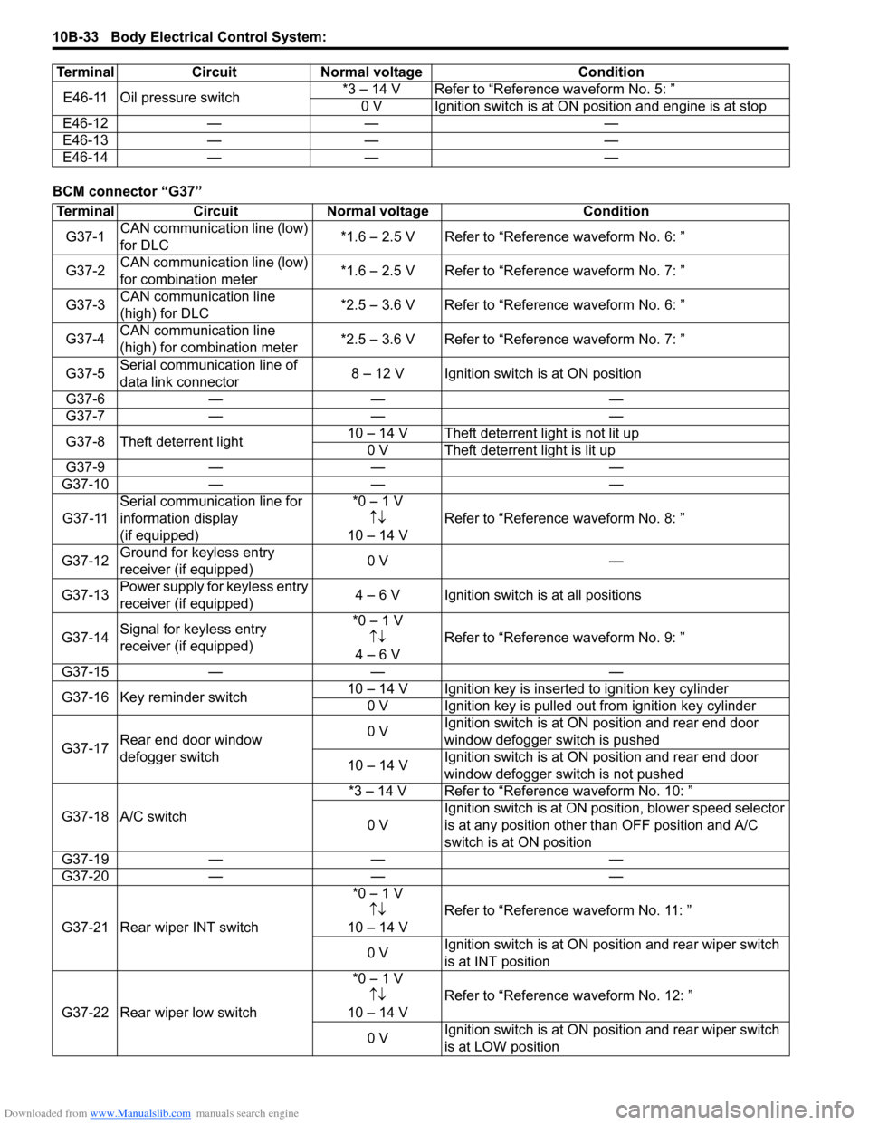
BCM connector “G37”E46-11 Oil pressure switch
*3 – 14 V Refer to “Reference waveform No. 5: ”
0 V Ignition switch is at ON position and engine is at stop
E46-12 — — —
E46-13 — — —
E46-14 — — —
Terminal Circuit Normal voltage Condition
Terminal
CircuitNormal voltage Condition
G37-1 CAN communication line (low)
for DLC *1.6 – 2.5 V Refer to “Reference waveform No. 6: ”
G37-2 CAN communication line (low)
for combination meter *1.6 – 2.5 V Refer to “Reference waveform No. 7: ”
G37-3 CAN communication line
(high) for DLC *2.5 – 3.6 V Refer to “Reference waveform No. 6: ”
G37-4 CAN communication line
(high) for combination meter *2.5 – 3.6 V Refer to “Reference waveform No. 7: ”
G37-5 Serial communication line of
data link connector 8 – 12 V Ignition switch is at ON position
G37-6 — — —
G37-7 — — —
G37-8 Theft deterrent light 10 – 14 V Theft deterrent light is not lit up
0 V Theft deterrent light is lit up
G37-9 — — —
G37-10 — — —
G37-11 Serial communication line for
information display
(if equipped) *0 – 1 V
↑↓
10 – 14 V Refer to “Reference
waveform No. 8: ”
G37-12 Ground for keyless entry
receiver (if equipped) 0 V
—
G37-13 Power supply for keyless entry
receiver (if equipped) 4 – 6 V Ignition switch is at all positions
G37-14 Signal for keyless entry
receiver (if equipped) *0 – 1 V
↑↓
4 – 6 V Refer to “Reference
waveform No. 9: ”
G37-15 — — —
G37-16 Key reminder switch 10 – 14 V Ignition key is inserted to ignition key cylinder
0 V Ignition key is pulled out from ignition key cylinder
G37-17 Rear end door window
defogger switch 0 V
Ignition switch is at ON
position and rear end door
window defogger switch is pushed
10 – 14 V Ignition switch is at ON
position and rear end door
window defogger switch is not pushed
G37-18 A/C switch *3 – 14 V Refer to “Reference waveform No. 10: ”
0 V Ignition switch is at ON pos
ition, blower speed selector
is at any position other than OFF position and A/C
switch is at ON position
G37-19 — — —
G37-20 — — —
G37-21 Rear wiper INT switch *0 – 1 V
↑↓
10 – 14 V Refer to “Reference
waveform No. 11: ”
0 V Ignition switch is at ON pos
ition and rear wiper switch
is at INT position
G37-22 Rear wiper low switch *0 – 1 V
↑↓
10 – 14 V Refer to “Reference
waveform No. 12: ”
0 V Ignition switch is at ON pos
ition and rear wiper switch
is at LOW position
Page 1437 of 1496
Downloaded from www.Manualslib.com manuals search engine Body Electrical Control System: 10B-34
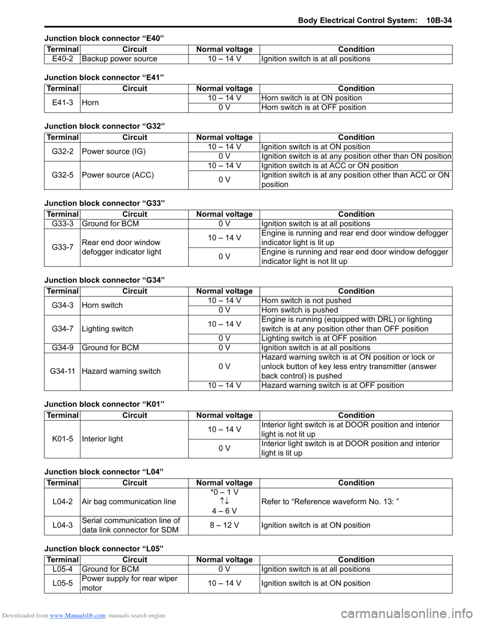
Junction block connector “E40”
Junction block connector “E41”
Junction block connector “G32”
Junction block connector “G33”
Junction block connector “G34”
Junction block connector “K01”
Junction block connector “L04”
Junction block connector “L05”Terminal Circuit Normal voltage Condition
E40-2 Backup power source 10 – 14 V Igni tion switch is at all positions
TerminalCircuitNormal voltage Condition
E41-3 Horn 10 – 14 V Horn switch is at ON position
0 V Horn switch is at OFF position
Terminal CircuitNormal voltage Condition
G32-2 Power source (IG) 10 – 14 V Ignition switch is at ON position
0 V Ignition switch is at any position other than ON position
G32-5 Power source (ACC) 10 – 14 V Ignition switch is at ACC or ON position
0 V Ignition switch is at any position other than ACC or ON
position
Terminal
CircuitNormal voltage Condition
G33-3 Ground for BCM 0 V Ignition switch is at all positions
G33-7 Rear end door window
defogger indicator light 10 – 14 V
Engine is running and rear end door window defogger
indicator light is lit up
0 V Engine is running and rear end door window defogger
indicator light is not lit up
Terminal
CircuitNormal voltage Condition
G34-3 Horn switch 10 – 14 V Horn switch is not pushed
0 V Horn switch is pushed
G34-7 Lighting switch 10 – 14 VEngine is running (equipped with DRL) or lighting
switch is at any position other than OFF position
0 V Lighting switch is at OFF position
G34-9 Ground for BCM 0 V Ignition switch is at all positions
G34-11 Hazard warning switch 0 VHazard warning switch is at
ON position or lock or
unlock button of key less entry transmitter (answer
back control) is pushed
10 – 14 V Hazard warning switch is at OFF position
Terminal CircuitNormal voltage Condition
K01-5 Interior light 10 – 14 V
Interior light switch is at
DOOR position and interior
light is not lit up
0 V Interior light switch is at
DOOR position and interior
light is lit up
Terminal CircuitNormal voltage Condition
L04-2 Air bag communication line *0 – 1 V
↑↓
4 – 6 V Refer to “Reference
waveform No. 13: ”
L04-3 Serial communication line of
data link connector for SDM 8 – 12 V Ignition switch is at ON position
Terminal
CircuitNormal voltage Condition
L05-4 Ground for BCM 0 V Ignition switch is at all positions
L05-5 Power supply for rear wiper
motor 10 – 14 V Ignition switch is at ON position
Page 1438 of 1496
Downloaded from www.Manualslib.com manuals search engine 10B-35 Body Electrical Control System:
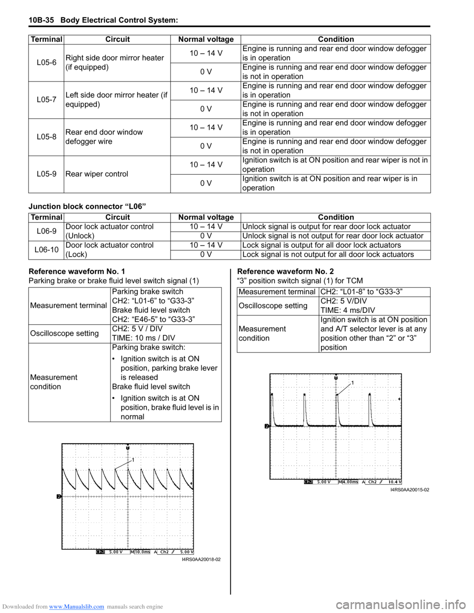
Junction block connector “L06”
Reference waveform No. 1
Parking brake or brake fluid level switch signal (1)Reference waveform No. 2
“3” position switch signal (1) for TCM
L05-6
Right side door mirror heater
(if equipped) 10 – 14 V
Engine is running and rear end door window defogger
is in operation
0 V Engine is running and rear end door window defogger
is not in operation
L05-7 Left side door mirror heater (if
equipped) 10 – 14 V
Engine is running and rear end door window defogger
is in operation
0 V Engine is running and rear end door window defogger
is not in operation
L05-8 Rear end door window
defogger wire 10 – 14 V
Engine is running and rear end door window defogger
is in operation
0 V Engine is running and rear end door window defogger
is not in operation
L05-9 Rear wiper control 10 – 14 V
Ignition switch is at ON posi
tion and rear wiper is not in
operation
0 V Ignition switch is at ON pos
ition and rear wiper is in
operation
Terminal Circuit Normal voltage Condition
Terminal
CircuitNormal voltage Condition
L06-9 Door lock actuator control
(Unlock) 10 – 14 V Unlock signal is outpu
t for rear door lock actuator
0 V Unlock signal is not output for rear door lock actuator
L06-10 Door lock actuator control
(Lock) 10 – 14 V Lock signal is output for all door lock actuators
0 V Lock signal is not output for all door lock actuators
Measurement terminal Parking brake switch
CH2: “L01-6” to “G33-3”
Brake fluid level switch
CH2: “E46-5” to “G33-3”
Oscilloscope setting CH2: 5 V / DIV
TIME: 10 ms / DIV
Measurement
condition Parking brake switch:
• Ignition switch is at ON
position, parking brake lever
is released
Brake fluid level switch
• Ignition switch is at ON position, brake fluid level is in
normal
I4RS0AA20018-02
Measurement terminal CH2: “L01-8” to “G33-3”
Oscilloscope setting CH2: 5 V/DIV
TIME: 4 ms/DIV
Measurement
condition Ignition switch is at ON position
and A/T selector lever is at any
position other than “2” or “3”
position
I4RS0AA20015-02
Page 1442 of 1496

Downloaded from www.Manualslib.com manuals search engine 10B-39 Body Electrical Control System:
Repair Instructions
BCM (Included in Junction Block Assembly)
Removal and Installation
S7RS0BA206001
CAUTION!
Do not attempt removal of BCM from junction
block assembly as it may cause contact
failure.
If there is faulty condition in BCM, replace
junction block assembly.
Removal
1) Disconnect negative (–) cable from battery.
2) Disable air bag system referring to “Disabling Air Bag System in Section 8B”.
3) Remove dash side trim (1) and steering column hole cover (2).
4) Remove junction block assembly mounting nuts (3).
5) Disconnect connectors from BCM and junction block assembly.
6) Detach wiring harness clamp from junction block assembly.
Installation
Reverse removal procedure for installation, noting
following points.
• Connect connectors securely.
• Enable air bag system referring to “Enabling Air Bag System in Section 8B”.
Outside Air Temperature Sensor Removal and
Installation
S7RS0BA206002
For removal and installation, refer to “Outside Air
Temperature Sensor Removal and Installation (If
Equipped) in Section 9C”.
Outside Air Temperature Sensor InspectionS7RS0BA206003
For inspection, refer to “Outside Air Temperature Sensor
Inspection (If Equipped) in Section 9C”.
Security Alarm Mode Selection Procedure (If
Equipped)
S7RS0BA206004
Security alarm mode can be selected by performing the
following procedure.
1) Confirm that all doors are closed, all doors are unlocked and ignition key is inserted in ignition key
cylinder.
2) Remove ignition key from ignition key cylinder.
3) Perform Step a) through e) described below within 15 seconds.
a) Insert ignition key (1) in ignition key cylinder (2).
b) Remove ignition key from ignition key cylinder.
c) Repeat Step a) and b) twice.
d) Insert ignition key in ignition key cylinder.
e) Push lock side (3) of driver side manual lock switch (4) 3 times.
4) When Step 3) is completed, the mode changes to the next one automatically. The warning buzzer
(located in BCM) sounds by the number of specified
for each mode as follows.
• Changed from A mode to B mode: Buzzer sounds 4 times
• Changed from B mode to A mode: Buzzer sounds once
4. BCM 5. Junction block assembly
I4RS0BA20010-01
4
3
1
2
I5RS0DA20007-01
Page 1444 of 1496
Downloaded from www.Manualslib.com manuals search engine 10C-1 Immobilizer Control System:
Control Systems
Immobilizer Control System
Precautions
Precautions in Diagnosing TroublesS7RS0BA300001
• Before confirming the diagnostic trouble code (DTC),
do not disconnect connector from ECM, battery cable
from battery, ground wire harness, or main fuse. Such
disconnection will erase DTC stored in ECM.
• DTC stored in ECM memory can be checked as well as cleared by using SUZUKI scan tool. Before using
SUZUKI scan tool, read its operator’s manual
carefully to know how to use it and what functions are
available.
• Be sure to read “Precautions for Electrical Circuit Service in Section 00” before inspection.
• Communication of ECM, BCM, keyless start control module (if equipped), ABS / ESP ® control module,
steering angle sensor (ESP ® model), combination
meter and TCM (A/T model) is established by CAN
(Controller Area Network). Therefore, handle CAN
communication lines with care referring to “Precaution
for CAN Communication System in Section 00”. For
CAN communication system, refer to description on
“CAN Communication System Description in Section
1A”.
Precaution in Replacing ECMS7RS0BA300002
• If ECM is replaced with new or used one without immobilizer control function , the engine will not be
started. In case of the above, check if the newly
installed ECM has immobilizer control function.
• After ECM is replaced with new one or used one, the transponder code in the transponder built in the
ignition key has to be registered with ECM. Or, the
engine cannot be started up. For the registration
procedure, refer to “Procedure after ECM
Replacement”.
Precautions in Handling Immobilizer Control
System
S7RS0BA300003
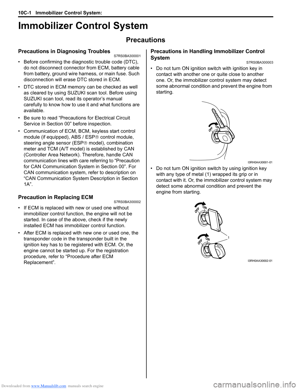
• Do not turn ON ignition sw itch with ignition key in
contact with another one or quite close to another
one. Or, the immobilizer co ntrol system may detect
some abnormal condition and prevent the engine from
starting.
• Do not turn ON ignition switch by using ignition key with any type of metal (1) wrapped its grip or in
contact with it. Or, the i mmobilizer control system may
detect some abnormal condition and prevent the
engine from starting.
I3RH0AA30001-01
1
I3RH0AA30002-01
Page 1445 of 1496
Downloaded from www.Manualslib.com manuals search engine Immobilizer Control System: 10C-2
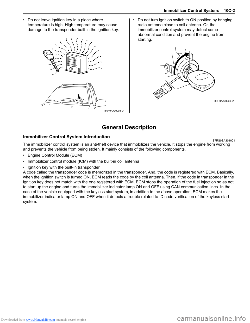
• Do not leave ignition key in a place where
temperature is high. High temperature may cause
damage to the transponder built in the ignition key. • Do not turn ignition switch to ON position by bringing
radio antenna close to coil antenna. Or, the
immobilizer control syst em may detect some
abnormal condition and prevent the engine from
starting.
General Description
Immobilizer Control System IntroductionS7RS0BA301001
The immobilizer control system is an anti-theft device that immobilizes the vehicle. It stops the engine from working
and prevents the vehicle from being stolen. It mainly consists of the following components.
• Engine Control Module (ECM)
• Immobilizer control module (ICM) with the built-in coil antenna
• Ignition key with the built-in transponder
A code called the transponder code is memorized in the tran sponder. And, the code is registered with ECM. Basically,
when the ignition switch is turned ON, ECM reads the code by the coil antenna. Then, if the code in transponder in the
ignition key does not match with the one registered with ECM, ECM stops the operati on of the fuel injection so as not
to start up the engine and turns the immobilizer indi cator lamp ON and OFF using CA N communication lines. In the
case of the vehicle equipped with the keyless start system , in addition to the above operation, ECM makes the
immobilizer indicator lamp ON and OFF when it detects a trouble related to ID code verification of the keyless start
system.
I3RH0AA30003-01
I3RH0AA30004-01