ABS SYSTEM SUZUKI SWIFT 2008 2.G Service Manual PDF
[x] Cancel search | Manufacturer: SUZUKI, Model Year: 2008, Model line: SWIFT, Model: SUZUKI SWIFT 2008 2.GPages: 1496, PDF Size: 34.44 MB
Page 872 of 1496
Downloaded from www.Manualslib.com manuals search engine 6B-1 Steering Wheel and Column:
Steeri ng
Steering Wheel and Column
Precautions
Service Precautions of Steering Wheel and
Column
S7RS0B6200001
For service precautions, refer to “Precautions on Service
and Diagnosis of Air Bag System in Section 8B”.
Service and Diagnosis
For diagnosis and servicing, refer to “Precautions on
Service and Diagnosis of Air Bag System in Section 8B”.
Disabling Air Bag System
For disabling air bag system, refer to “Disabling Air Bag
System in Section 8B”. Enabling Air Bag System
For enabling air bag system, refer to “Enabling Air Bag
System in Section 8B”.
Handling and Storage
For handling and storage, refer to “Precautions on
Handling and Storage of Air Bag System Components in
Section 8B”.
Disposal
For disposal, refer to “Prec
autions on Disposal of Air
Bag and Seat Belt Pretensioner in Section 8B”.
General Description
Steering Wheel and Column ConstructionS7RS0B6201001
This double tube type steering column has the following three important features in addition to the steering function:
• The column is energy absorbing, desig ned to compress in a front-end collision.
• The ignition switch and lock are mounted conveniently on this column.
• With the column mounted lock, the ignition and steering op erations can be locked to inhibit theft of the vehicle.
To insure the energy absorbing action, it is important th at only the specified screws, bolts and nuts be used as
designated, and that they are tightened to the specified torque. When the column assembly is removed from the
vehicle, special care must be taken in handling it. Use of a steering wheel puller or a sharp blow on the end of the
steering shaft, leaning on the assembly, or dropping the a ssembly could shear the plastic shear pins which maintain
column length and position.
The driver air bag (inflator) module is one of the supplemental restraint (air bag) system components and is mounted
to the center of the steering wheel. During certain frontal crashes, the air bag system supplements the restraint of the
driver’s and passenger’s seat belts by deploying the air b ags. The air bag (inflator) module should be handled with
care to prevent accidental deployment. When servicing, be sure to observe “Precautions on Service and Diagnosis of
Air Bag System in Section 8B”.
Page 884 of 1496
Downloaded from www.Manualslib.com manuals search engine 6C-2 Power Assisted Steering System:
General Description
P/S System DescriptionS7RS0B6301001
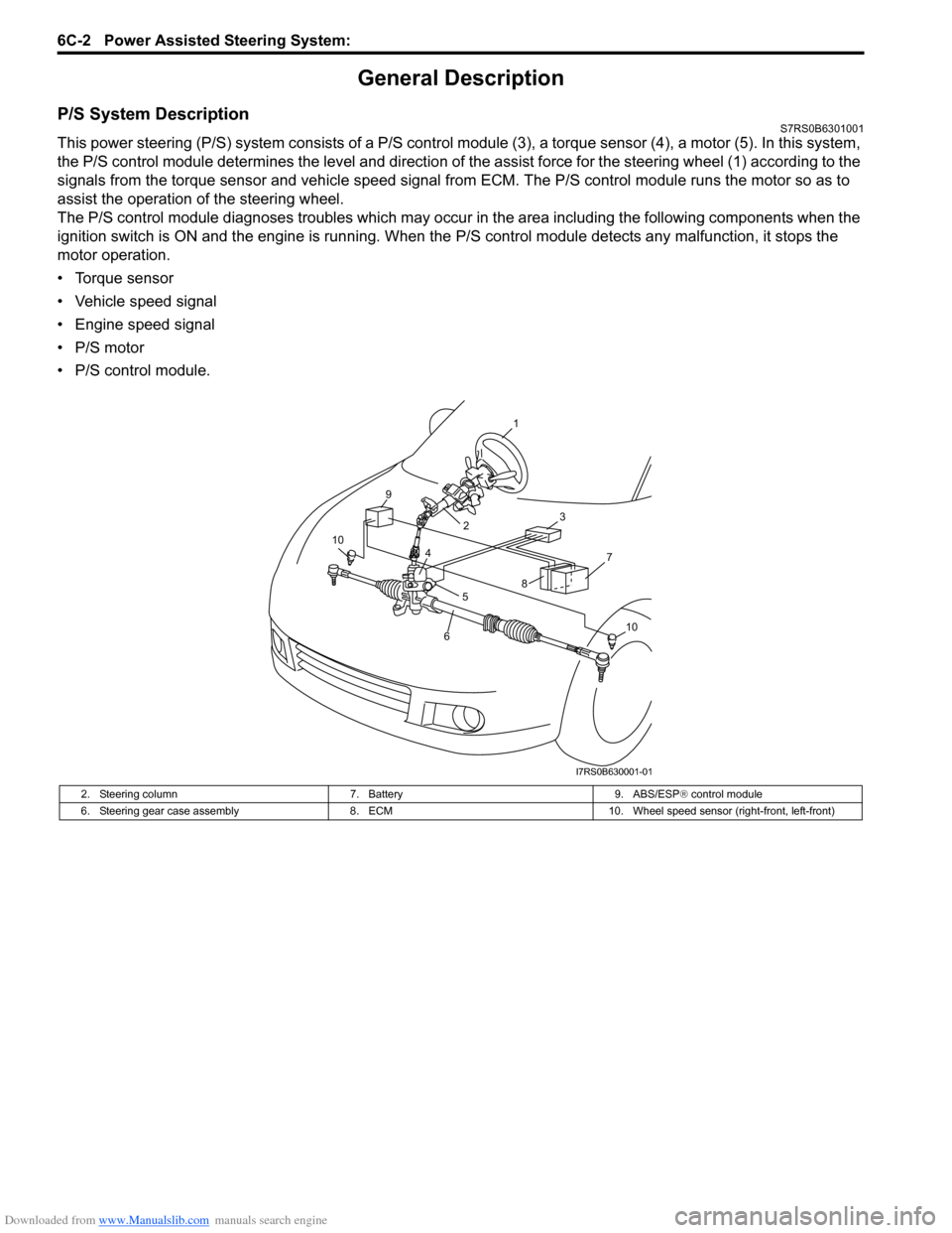
This power steering (P/S) system consists of a P/S control module (3), a torque sensor (4), a motor (5). In this system,
the P/S control module determines the level and direction of the assist force for the steering wheel (1) according to the
signals from the torque sensor and vehicle speed signal from ECM. The P/S control module runs the motor so as to
assist the operation of the steering wheel.
The P/S control module diagnoses troubles which may occur in the area including the following components when the
ignition switch is ON and the engine is running. When the P/S control module detects any malfunction, it stops the
motor operation.
• Torque sensor
• Vehicle speed signal
• Engine speed signal
• P/S motor
• P/S control module.
2. Steering column 7. Battery9. ABS/ESP® control module
6. Steering gear case assembly 8. ECM10. Wheel speed sensor (right-front, left-front)
7
3
9
10
10
1
2
4
5
6
8
I7RS0B630001-01
Page 886 of 1496
Downloaded from www.Manualslib.com manuals search engine 6C-4 Power Assisted Steering System:
Schematic and Routing Diagram
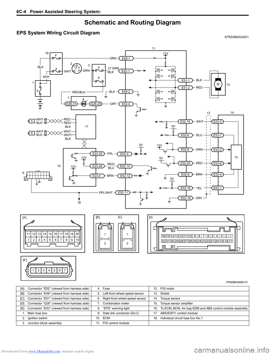
EPS System Wiring Circuit DiagramS7RS0B6302001
M
5V
BRNRED/
BLU
BLK
RED
WHT
BLU
GRN
BRN YEL
E52-11
E52-14E52-12
E23-4
E23-26
E23-25 E51-1
E51-2
E52-18
E53-5
E53-7
E52-6
E52-8
E53-2
E52-9
E52-16
E52-19
GRY
PPL/WHT
[A ]
[E ]
12 3
4 5 67
89
11
10
12 13
141516
17 18 19 20
1
2
[B ][C ]
1210 9 8 7654 3 21
16 15 14 13 12 11
26 25 24 2322 21 20 19 18 17
32 31 30 29 28 27
[D]
5V
PPL
E52-4
11
12
13 14
15
10
9
16
12V
5V
5V
12V
REDE52-20E53-6
E53-4
E53-1
7654321
5
REDRED/
BLKWHT
6WHTWHT/BLKWHTBLK
12V
12V
17BLK
GRY
LT GRN
/BLK
E52-1
E52-5
E49-1
GRNGRNWHTBLK
WHY
G28-25G28-31
RED/BLK
18
3
4
4
7 8
4
4
1 2
4
E49-2BLK
I7RS0B630002-01
[A]: Connector “E52” (viewed from harness side) 4. Fuse 12. P/S motor
[B]: Connector “E49” (viewed from harness side ) 5. Left-front wheel speed sensor 13. Shield
[C]: Connector “E51” (viewed from harness side) 6 . Right-front wheel speed sensor 14. Torque sensor
[D]: Connector “G28” (viewed from harness side) 7. Combination meter 15. Torque sensor amplifier
[E]: Connector “E53” (viewed from harness side) 8. “EPS” warning light16. To ECM, BCM, Air bag SDM and ABS control module assembly
1. Main fuse box 9. Date link connector (DLC) 17. ABS/ESP ® control module
2. Ignition switch 10. ECM18. Individual circuit fuse box No.1
3. Junction block assembly 11. P/S control module
Page 892 of 1496

Downloaded from www.Manualslib.com manuals search engine 6C-10 Power Assisted Steering System:
�) C1121 No vehicle speed signal
(60 seconds or more) Vehicle speed signal is 0 km/h
even though engine speed is
more than 4000 rpm for more than
60 seconds continuously (before
elapse of 5 min from engine start)
or vehicle speed signal is 0 km/h
even though engine speed is
more than 2500 rpm for more than
60 seconds continuously (after
elapse of 5 min for engine start). • Vehicle speed signal circuit
• Wheel speed sensor
•ECM
• P/S control module
• ABS control module
• CAN communication circuit
Not
applicable
�) C1122 Engine speed signal Engine speed signal is less than
220 rpm for more than 0.8
seconds.
or
Engine speed signal is less than
220 rpm for more than 20
seconds continuously even
though vehicle speed signal is
more than 50 km/h.• Engine speed signal circuit
•ECM
• P/S control module
• Vehicle speed signal
1 driving
cycle
�) C1123 No vehicle speed signal
(30 seconds or more) Vehicle speed signal is 0 km/h
with continuously more than 3
driving cycles even though engine
speed is more than 4000 rpm for
more than 30 seconds
continuously (before elapse of 5
min from engine start).
or
vehicle speed signal is 0 km/h
with continuously more than 3
driving cycles even though engine
speed is more than 2500 rpm for
more than 30 seconds
continuously (after elapse of 5 min
for engine start). • Vehicle speed signal circuit
• Wheel speed sensor
•ECM
• P/S control module
• ABS control module
• CAN communication circuit
3 driving
cycles
�) C1124 Vehicle speed performance
(Impossible deceleration) Vehicle speed signal is less than 5
km/h for more
than 5 seconds
continuously with more than
specified deceleration speed (–20
m/s
2) from over 20 km/h. Not
applicable
�) C1141 P/S motor circuit voltage Voltage between both motor drive
circuits is more than 8.5 V or less
than 0.2 V for 0.5 seconds
continuously while motor is not
drived.
• P/S motor circuit
• P/S motor
• P/S control module1 driving
cycle
�) C1142 P/S motor circuit range /
performance Measured motor drive current is
more than 10 A as compared with
target motor drive current. 1 driving
cycle
DTC No. Detecting item
Detecting condition
(DTC will set when detecting) Trouble area MIL
Page 895 of 1496
Downloaded from www.Manualslib.com manuals search engine Power Assisted Steering System: 6C-13
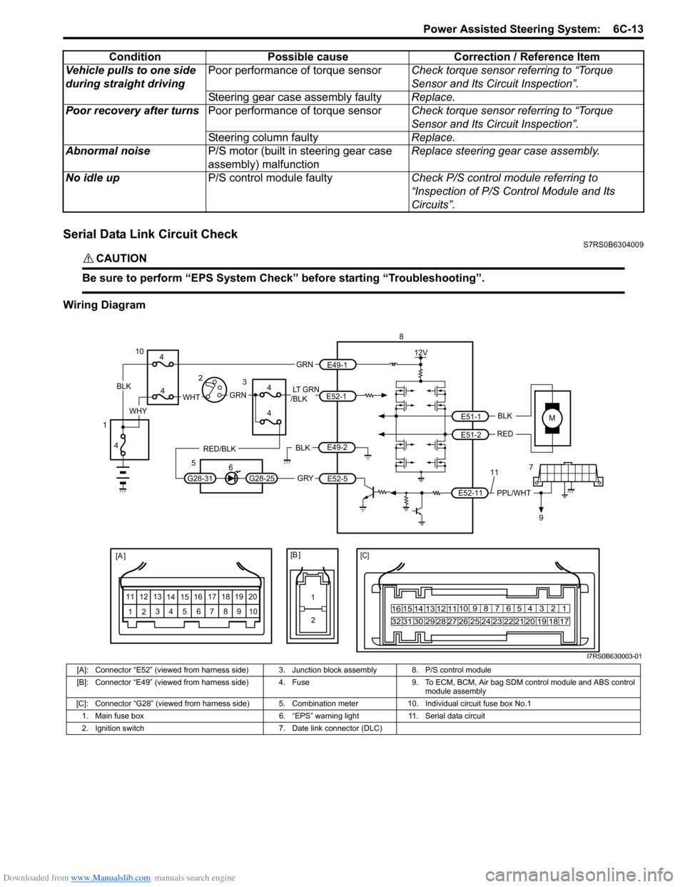
Serial Data Link Circuit CheckS7RS0B6304009
CAUTION!
Be sure to perform “EPS System Check” before starting “Troubleshooting”.
Wiring DiagramVehicle pulls to one side
during straight driving
Poor performance of torque sensor
Check torque sensor referring to “Torque
Sensor and Its Circuit Inspection”.
Steering gear case assembly faulty Replace.
Poor recovery after turns Poor performance of torque sensor Check torque sensor referring to “Torque
Sensor and Its Circuit Inspection”.
Steering column faulty Replace.
Abnormal noise P/S motor (built in steering gear case
assembly) malfunction Replace steering gear case assembly.
No idle up P/S control module faulty Check P/S control module referring to
“Inspection of P/S Control Module and Its
Circuits”.
Condition Possible cause Correction / Reference Item
MBLK
RED
E52-11 E51-1
E51-2PPL/WHT
[A ]
12
3
4 5 67
89
11
10
12 13
141516
17 18 19 2010 9 8 7654 3 21
16 15 14 13 12 11
26 25 24 2322 21 20 19 18 17
32 31 30 29 28 27
[C]
8
79
12V
[B ]
11
12
GRY
LT GRN
/BLK
E52-1
E52-5
E49-1
GRNGRNWHTBLK
WHY
G28-25G28-31
RED/BLK
10
3
4
4
5 6
4
4
1 2
4
E49-2BLK
I7RS0B630003-01
[A]: Connector “E52” (viewed from harness side) 3. Junction block assembly 8. P/S control module
[B]: Connector “E49” (viewed from harness side) 4. Fuse 9. T o ECM, BCM, Air bag SDM control module and ABS control
module assembly
[C]: Connector “G28” (viewed from harness side) 5. Comb ination meter 10. Individual circuit fuse box No.1
1. Main fuse box 6. “EPS” warning light 11. Serial data circuit
2. Ignition switch 7. Date link connector (DLC)
Page 896 of 1496
Downloaded from www.Manualslib.com manuals search engine 6C-14 Power Assisted Steering System:
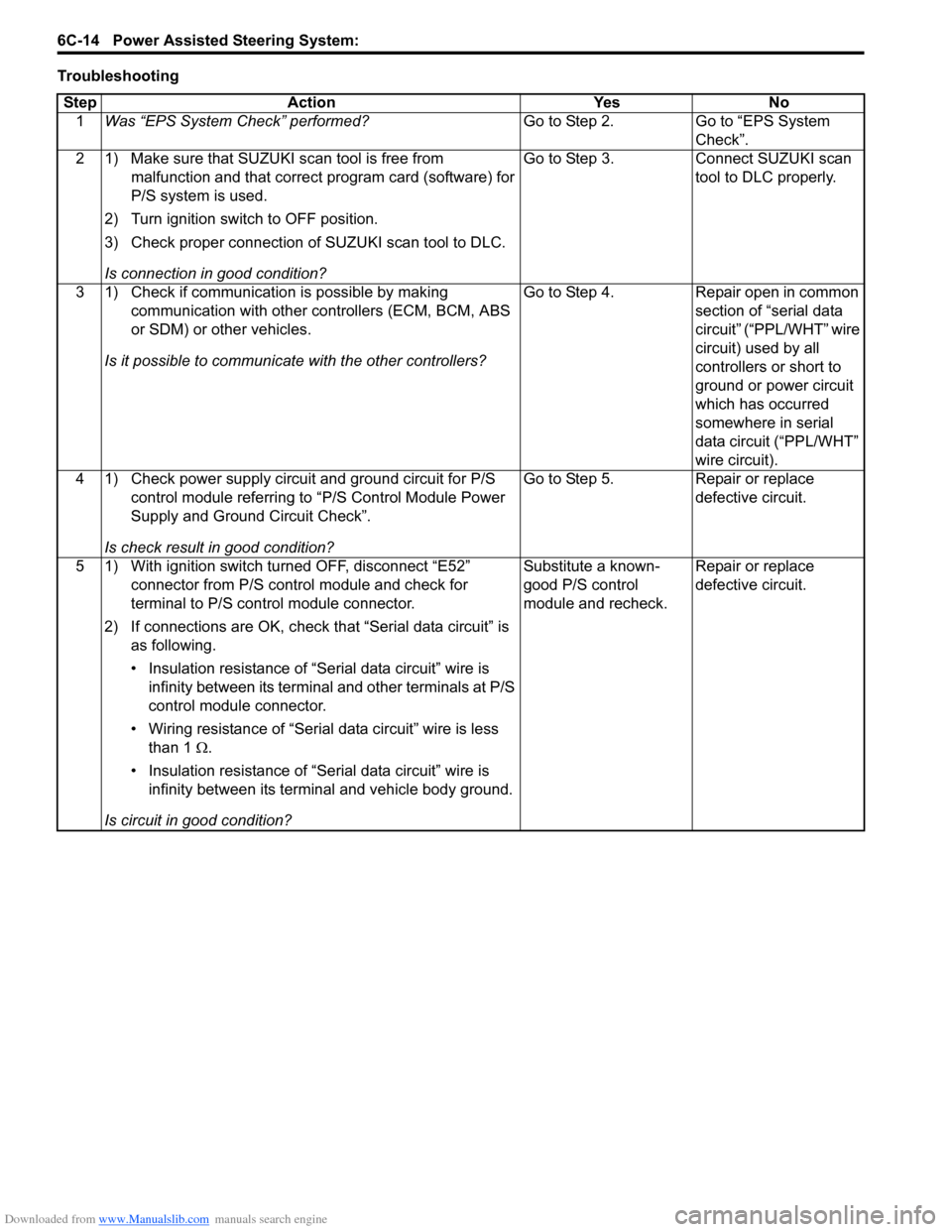
TroubleshootingStep Action Yes No 1 Was “EPS System Check” performed? Go to Step 2. Go to “EPS System
Check”.
2 1) Make sure that SUZUKI scan tool is free from malfunction and that correct program card (software) for
P/S system is used.
2) Turn ignition switch to OFF position.
3) Check proper connection of SUZUKI scan tool to DLC.
Is connection in good condition? Go to Step 3. Connect SUZUKI scan
tool to DLC properly.
3 1) Check if communication is possible by making communication with other controllers (ECM, BCM, ABS
or SDM) or other vehicles.
Is it possible to communic ate with the other controllers? Go to Step 4. Repair open in common
section of “serial data
circuit” (“PPL/WHT” wire
circuit) used by all
controllers or short to
ground or power circuit
which has occurred
somewhere in serial
data circuit (“PPL/WHT”
wire circuit).
4 1) Check power supply circuit and ground circuit for P/S control module referring to “P/S Control Module Power
Supply and Ground Circuit Check”.
Is check result in good condition? Go to Step 5. Repair or replace
defective circuit.
5 1) With ignition switch turned OFF, disconnect “E52” connector from P/S control module and check for
terminal to P/S control module connector.
2) If connections are OK, check t hat “Serial data circuit” is
as following.
• Insulation resistance of “Serial data circuit” wire is infinity between its terminal and other terminals at P/S
control module connector.
• Wiring resistance of “Seria l data circuit” wire is less
than 1 Ω.
• Insulation resistance of “Serial data circuit” wire is infinity between its terminal and vehicle body ground.
Is circuit in good condition? Substitute a known-
good P/S control
module and recheck.
Repair or replace
defective circuit.
Page 908 of 1496
Downloaded from www.Manualslib.com manuals search engine 6C-26 Power Assisted Steering System:
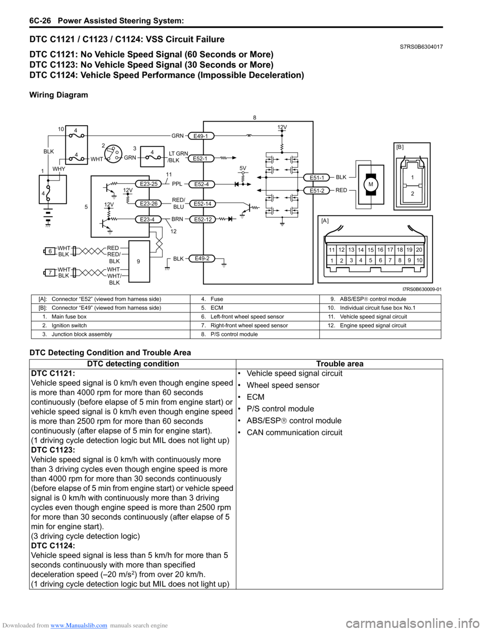
DTC C1121 / C1123 / C1124: VSS Circuit FailureS7RS0B6304017
DTC C1121: No Vehicle Speed Signal (60 Seconds or More)
DTC C1123: No Vehicle Speed Signal (30 Seconds or More)
DTC C1124: Vehicle Speed Performance (Impossible Deceleration)
Wiring Diagram
DTC Detecting Condition and Trouble Area
M
BRNRED/
BLU
BLK
RED
E52-14
E52-12
E23-4
E23-26
E23-25 E51-1
E51-2
[A ]
12
3
4 5 67
89
11
10
12 13
141516
17 18 19 20
5V
PPL
E52-4
8
5
12V
E49-2BLK
12V
12V
6REDRED/ BLKWHT
7WHTWHT/BLKWHTBLK BLK
111
2
[B ]
9
LT GRN
/BLKE52-1 E49-1
GRNGRNWHTBLK
WHY
10
3
4
4
4
4
1 2
12
I7RS0B630009-01
[A]: Connector “E52” (viewed from harness side)
4. Fuse9. ABS/ESP® control module
[B]: Connector “E49” (viewed from harness si de)5. ECM 10. Individual circuit fuse box No.1
1. Main fuse box 6. Left-front wheel speed sensor11. Vehicle speed signal circuit
2. Ignition switch 7. Right-front wheel speed sensor 12. Engine speed signal circuit
3. Junction block assembly 8. P/S control module
DTC detecting condition Trouble area
DTC C1121:
Vehicle speed signal is 0 km/h even though engine speed
is more than 4000 rpm for more than 60 seconds
continuously (before elapse of 5 min from engine start) or
vehicle speed signal is 0 km/h even though engine speed
is more than 2500 rpm for more than 60 seconds
continuously (after elapse of 5 min for engine start).
(1 driving cycle detection logic but MIL does not light up)
DTC C1123:
Vehicle speed signal is 0 km/h with continuously more
than 3 driving cycles even though engine speed is more
than 4000 rpm for more than 30 seconds continuously
(before elapse of 5 min from engine start) or vehicle speed
signal is 0 km/h with continuously more than 3 driving
cycles even though engine speed is more than 2500 rpm
for more than 30 seconds continuously (after elapse of 5
min for engine start).
(3 driving cycle detection logic)
DTC C1124:
Vehicle speed signal is less than 5 km/h for more than 5
seconds continuously with more than specified
deceleration speed (–20 m/s
2) from over 20 km/h.
(1 driving cycle detection logic but MIL does not light up) • Vehicle speed signal circuit
• Wheel speed sensor
•ECM
• P/S control module
• ABS/ESP®
control module
• CAN communication circuit
Page 909 of 1496
Downloaded from www.Manualslib.com manuals search engine Power Assisted Steering System: 6C-27
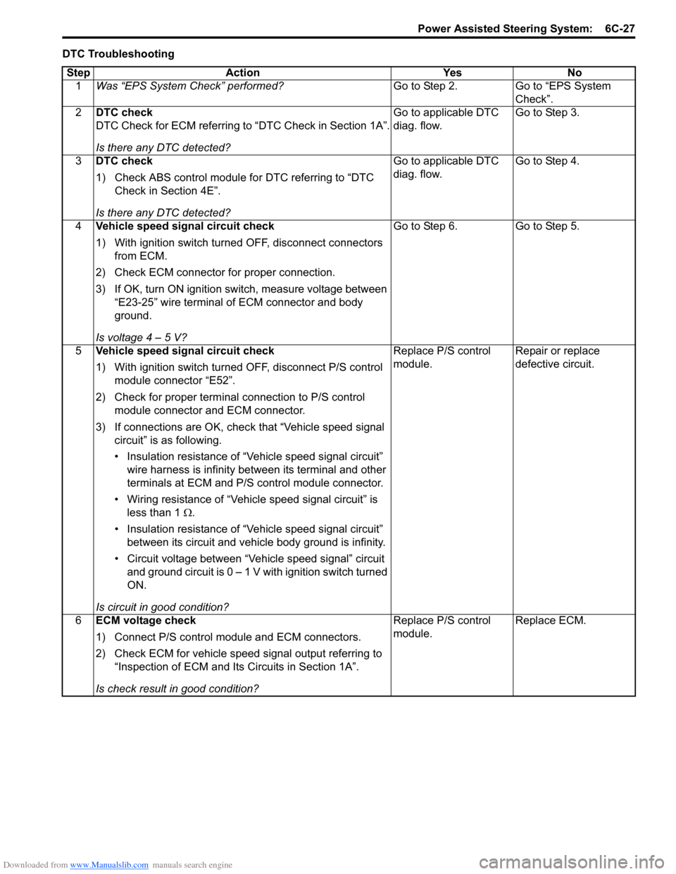
DTC TroubleshootingStep Action Yes No 1 Was “EPS System Check” performed? Go to Step 2. Go to “EPS System
Check”.
2 DTC check
DTC Check for ECM referring to “DTC Check in Section 1A”.
Is there any DTC detected? Go to applicable DTC
diag. flow.
Go to Step 3.
3 DTC check
1) Check ABS control module for DTC referring to “DTC
Check in Section 4E”.
Is there any DTC detected? Go to applicable DTC
diag. flow.
Go to Step 4.
4 Vehicle speed signal circuit check
1) With ignition switch turned OFF, disconnect connectors
from ECM.
2) Check ECM connector for proper connection.
3) If OK, turn ON ignition switch, measure voltage between “E23-25” wire terminal of ECM connector and body
ground.
Is voltage 4 – 5 V? Go to Step 6.
Go to Step 5.
5 Vehicle speed signal circuit check
1) With ignition switch turned OFF, disconnect P/S control
module connector “E52”.
2) Check for proper terminal connection to P/S control module connector and ECM connector.
3) If connections are OK, chec k that “Vehicle speed signal
circuit” is as following.
• Insulation resistance of “Vehicle speed signal circuit” wire harness is infinity between its terminal and other
terminals at ECM and P/S control module connector.
• Wiring resistance of “Vehicle speed signal circuit” is less than 1 Ω.
• Insulation resistance of “Vehicle speed signal circuit” between its circuit and vehicle body ground is infinity.
• Circuit voltage between “Vehicle speed signal” circuit and ground circuit is 0 – 1 V with ignition switch turned
ON.
Is circuit in good condition? Replace P/S control
module.
Repair or replace
defective circuit.
6 ECM voltage check
1) Connect P/S control mo dule and ECM connectors.
2) Check ECM for vehicle speed signal output referring to “Inspection of ECM and Its Circuits in Section 1A”.
Is check result in good condition? Replace P/S control
module.
Replace ECM.
Page 928 of 1496
Downloaded from www.Manualslib.com manuals search engine 6C-46 Power Assisted Steering System:
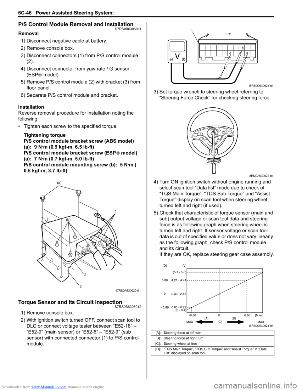
P/S Control Module Removal and InstallationS7RS0B6306011
Removal1) Disconnect negative cable at battery.
2) Remove console box.
3) Disconnect connectors (1) from P/S control module (2).
4) Disconnect connector from yaw rate / G sensor
(ESP ® model).
5) Remove P/S control module (2) with bracket (3) from floor panel.
6) Separate P/S control module and bracket.
Installation
Reverse removal procedure for installation noting the
following.
• Tighten each screw to the specified torque. Tightening torque
P/S control module bracket screw (ABS model)
(a): 9 N·m (0.9 kgf-m, 6.5 lb-ft)
P/S control module bracket screw (ESP ® model)
(a): 7 N·m (0.7 kgf-m, 5.0 lb-ft)
P/S control module mounting screw (b): 5 N·m (
0.5 kgf-m, 3.7 lb-ft)
Torque Sensor and Its Circuit InspectionS7RS0B6306012
1) Remove console box.
2) With ignition switch turned OFF, connect scan tool to DLC or connect voltage tester between “E52-18” –
“E52-9” (main sensor) or “E52-6” – “E52-9” (sub
sensor) with connected connector (1) to P/S control
module. 3) Set torque wrench to stee
ring wheel referring to
“Steering Force Check” for checking steering force.
4) Turn ON ignition switch without engine running and select scan tool “Data list” mode due to check of
“TQS Main Torque”, “TQS Sub Torque” and “Assist
Torque” display on scan tool when steering wheel
turned left and right (if used).
5) Check that characteristic of torque sensor (main and sub) output voltage or scan tool data and steering
force is as following graph when steering wheel is
turned left and right. If sensor voltage or scan tool
data is out of specified value or does not vary linearly
as the following graph, check P/S control module
and its circuit.
If they are OK, replace steering gear case assembly.
1
(a)
2
3
(b)
I7RS0A630020-01
[A]: Steering force at left turn
[B]: Steering force at right turn
[C]: Steering wheel at free
[D]: “TQS Main Torque”, “TQS Sub Torque” and “Assist Torque” in “Data List” displayed on scan tool
E52
18
9
6
9
6 18
1
I6RS0C630024-01
I3RM0A630022-01
0
[C] [N.m]
MAX MAX
[B]
[A]
2.33 - 2.68 [V]
[D]
0.65 - 0.72
(0 - 0.4)
4.21 - 4.41
(5.1 - 5.6)
6.86
-6.86
0
6.86
- 6.86
I6RS0C630021-04
Page 930 of 1496
Downloaded from www.Manualslib.com manuals search engine 6C-48 Power Assisted Steering System:
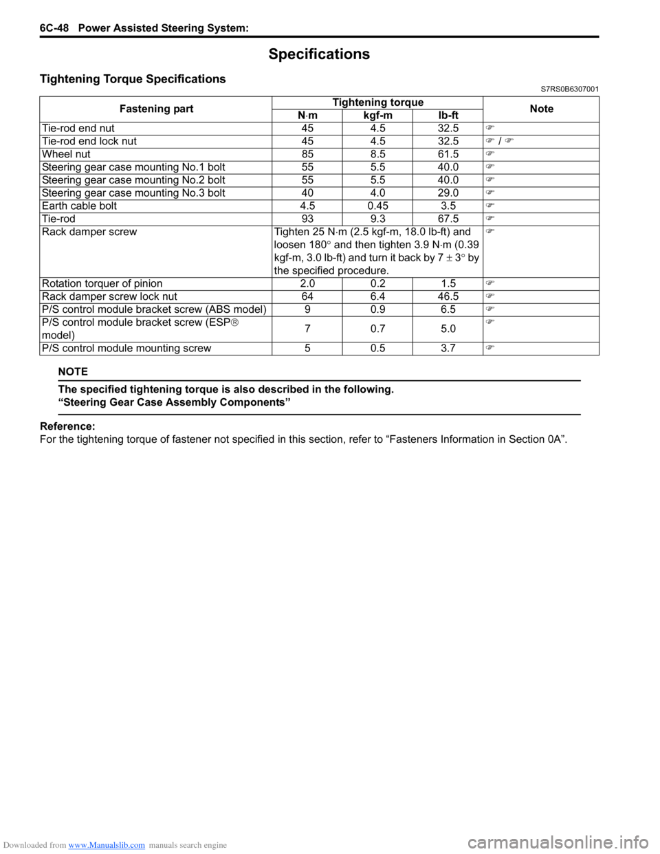
Specifications
Tightening Torque SpecificationsS7RS0B6307001
NOTE
The specified tightening torque is also described in the following.
“Steering Gear Case Assembly Components”
Reference:
For the tightening torque of fastener not specified in this section, refer to “Fasteners Information in Section 0A”.
Fastening part
Tightening torque
Note
N ⋅mkgf-mlb-ft
Tie-rod end nut 454.5 32.5 �)
Tie-rod end lock nut 454.5 32.5 �) / �)
Wheel nut 858.5 61.5 �)
Steering gear case mounting No.1 bolt 555.5 40.0 �)
Steering gear case mounting No.2 bolt 555.5 40.0 �)
Steering gear case mounting No.3 bolt 404.0 29.0 �)
Earth cable bolt 4.5 0.45 3.5�)
Tie-rod 939.3 67.5 �)
Rack damper screw Tighten 25 N⋅m (2.5 kgf-m, 18.0 lb-ft) and
loosen 180 ° and then tighten 3.9 N ⋅m (0.39
kgf-m, 3.0 lb-ft) and turn it back by 7 ± 3° by
the specified procedure. �)
Rotation torquer of pinion 2.00.2 1.5 �)
Rack damper screw lock nut 646.4 46.5 �)
P/S control module bracket screw (ABS model) 9 0.9 6.5�)
P/S control module bracket screw (ESP ®
model) 70
.7 5 .0 �)
P/S control module mounting screw 50.5 3.7 �)