Wiring diagram ecm SUZUKI SWIFT 2008 2.G Service Manual PDF
[x] Cancel search | Manufacturer: SUZUKI, Model Year: 2008, Model line: SWIFT, Model: SUZUKI SWIFT 2008 2.GPages: 1496, PDF Size: 34.44 MB
Page 583 of 1496
Downloaded from www.Manualslib.com manuals search engine Electronic Stability Program: 4F-9
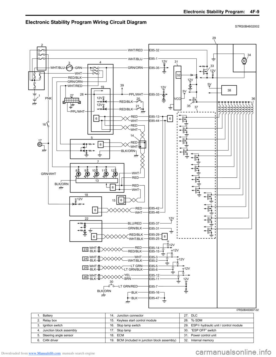
Electronic Stability Program Wiring Circuit DiagramS7RS0B4602002
WHT/BLU
WHT/BLUGRN
M
12V3
12V
5V
12V
VCC
WHT/RED
WHT
7
REDWHT
12V
12V
6 19
20
21RED/BLK
RED/BLK
GRN/WHT
PNK
12V
GRN/BLK
5V
LT GRN/RED
BLK/ORN
4
16
17
186
22
6 29
30 34
36
38
33
35
32
31
6
6 37
BLK
BLK
RED/BLKRED12V
BLKWHT
23
WHT/BLKWHT
12V
BLKWHT
24
BLKWHTLT GRN/BLKLT GRN
12V
25
BLKWHTBRN
12V
26YEL
12V
98101211
13
6BLK/ORN
1
227
5
WHT/REDGRN/ORN
BLK/ORN
REDWHT
REDWHT
PPL/WHT
6
REDWHT
REDWHT
6
REDWHT
RED/BLK
PPL/WHT
28
39
15 14
BLU/RED
GRN/ORN
12V
12V
E85-35
E85-33
E85-13E85-44
E85-46
E85-29E85-25
E85-37
E85-31
E85-14E85-15
E85-12E85-11
E85-16
E85-47
E85-3
E85-32
E85-1
E85-2
E85-5E85-6
E85-7
E85-42
RED/BLKWHT/BLK
I7RS0B460007-02
1. Battery 14. Junction connector 27. DLC
2. Relay box 15. Keyless start control module 28. To SDM
3. Ignition switch 16. Stop lamp switch 29. ESP® hydraulic unit / control module
4. Junction block assembly 17. Stop lamp 30. “ESP OFF” switch
5. Steering angle sensor 18. ECM 31. Power control unit
6. CAN driver 19. BCM (included in junction block assembly) 32. Internal memory
Page 600 of 1496
![SUZUKI SWIFT 2008 2.G Service Manual PDF Downloaded from www.Manualslib.com manuals search engine 4F-26 Electronic Stability Program:
Serial Data Link Circuit CheckS7RS0B4604012
Wiring Diagram
Inspection
[A]E85
161
15
2
3
4
5
6
7
8
9
10
11
SUZUKI SWIFT 2008 2.G Service Manual PDF Downloaded from www.Manualslib.com manuals search engine 4F-26 Electronic Stability Program:
Serial Data Link Circuit CheckS7RS0B4604012
Wiring Diagram
Inspection
[A]E85
161
15
2
3
4
5
6
7
8
9
10
11](/img/20/7607/w960_7607-599.png)
Downloaded from www.Manualslib.com manuals search engine 4F-26 Electronic Stability Program:
Serial Data Link Circuit CheckS7RS0B4604012
Wiring Diagram
Inspection
[A]E85
161
15
2
3
4
5
6
7
8
9
10
11
12
13
14
17
18
19
20
21
22
23
24
25
26
27
28
29
30
31
3233
34
35
36
37
38
39
40
41
42
43
44
45
46
47WHTGRN
3
E85-13REDWHT6 5E46-1E46-2
4
10
6
E85-16
E85-47BLKBLK
8
9
BLK/ORN
REDWHT
REDWHT
G37-4G37-2
G28-10G28-8
G28-16
G28-31
12V
12VE85-32E85-1
E85-35
WHT/REDWHT/BLU
GRN/ORN
6
2
1
7 1415 [B]
G37
E46
124
53
67
891011121314124
53
67
891011
1213141516171819202122
[C] G28
12345678910111213141516
17181920212223242526272829303132
12V
11
PPL/WHT
PPL/WHT
E85-33
E85-44
12
13
WHTWHT/REDB
G G1
RED/BLK
I6RS0B460012-01
[A]: ESP
® control module connector (viewed
from terminal side) 4. Junction block assembly 10. ESP
® hydraulic unit / control module assembly
[B]: BCM connector (viewed from harness side) 5. BCM (included in junction block
assembly) 11. Data link connector (DLC)
[C]: Combination meter connector (viewed from harness side) 6. CAN driver 12. To SDM
1. Battery 7. Combination meter 13. To ECM and P/S control module
2. Main fuse box 8. ESP ® warning lamp 14. Junction connector
3. Ignition switch 9. Lamp driver module 15. To steering angle sensor
Step Action YesNo
1 Check ESP ® warning lamp
1) Turn ignition switch to ON position.
Does ESP
® warning lamp come ON? Go to Step 2. Go to Step 6.
2 Check fuse
1) Turn ignition switch to OFF position.
Are main fuses for good condition? Go to Step 3. Replace fuse and check
for short.
3 Check ESP ® control module power supply circuit
1) Disconnect ESP ® control module connector.
2) Check for proper connection to ESP ® control module
connector at terminal “E85-35”.
3) If OK, then turn ignition switch to ON position and measure voltage between terminal “E85-35” and vehicle
body ground.
Is it 10 – 14 V? Go to Step 4.
“GRN/ORN” wire circuit
open.
Page 602 of 1496
Downloaded from www.Manualslib.com manuals search engine 4F-28 Electronic Stability Program:
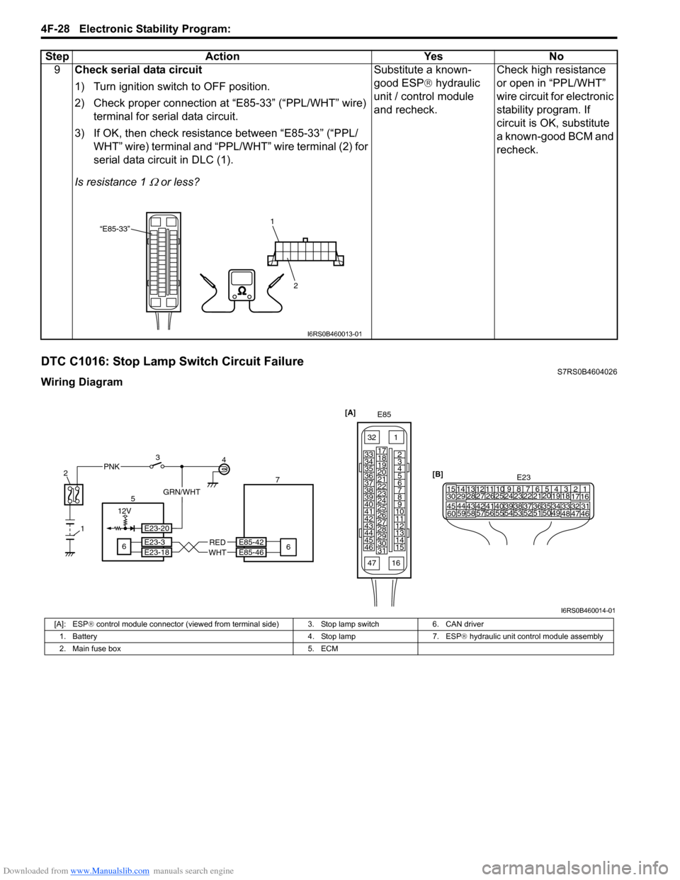
DTC C1016: Stop Lamp Switch Circuit FailureS7RS0B4604026
Wiring Diagram9
Check serial data circuit
1) Turn ignition switch to OFF position.
2) Check proper connection at “E85-33” (“PPL/WHT” wire)
terminal for serial data circuit.
3) If OK, then check resistance between “E85-33” (“PPL/ WHT” wire) terminal and “PPL/WHT” wire terminal (2) for
serial data circuit in DLC (1).
Is resistance 1
Ω or less? Substitute a known-
good ESP
® hydraulic
unit / control module
and recheck. Check high resistance
or open in “PPL/WHT”
wire circuit for electronic
stability program. If
circuit is OK, substitute
a known-good BCM and
recheck.
Step Action Yes No
“E85-33”
2
1
I6RS0B460013-01
[A]
E85
161
15
2
3
4
5
6
7
8
9
10
11
12
13
14
17
18
19
20
21
22
23
24
25
26
27
28
29
30
31
3233
34
35
36
37
38
39
40
41
42
43
44
45
46
47
[B]
21
E23 34
1819
5671011
17
20
47 46
495051
2122
52 16
25 9
24
14
29
5557 54 53
59
60 5826
27
28
15
30
56 4832 31343536374042 39 38
44
45 43 41 33
1213
2382
1
E85-42
E85-46
56RED
WHT
4
6 7
E23-3
E23-18
12V
PNK3
GRN/WHT
E23-20
I6RS0B460014-01
[A]: ESP
® control module connector (viewed from te rminal side) 3. Stop lamp switch 6. CAN driver
1. Battery 4. Stop lamp 7. ESP ® hydraulic unit control module assembly
2. Main fuse box 5. ECM
Page 623 of 1496
Downloaded from www.Manualslib.com manuals search engine Electronic Stability Program: 4F-49
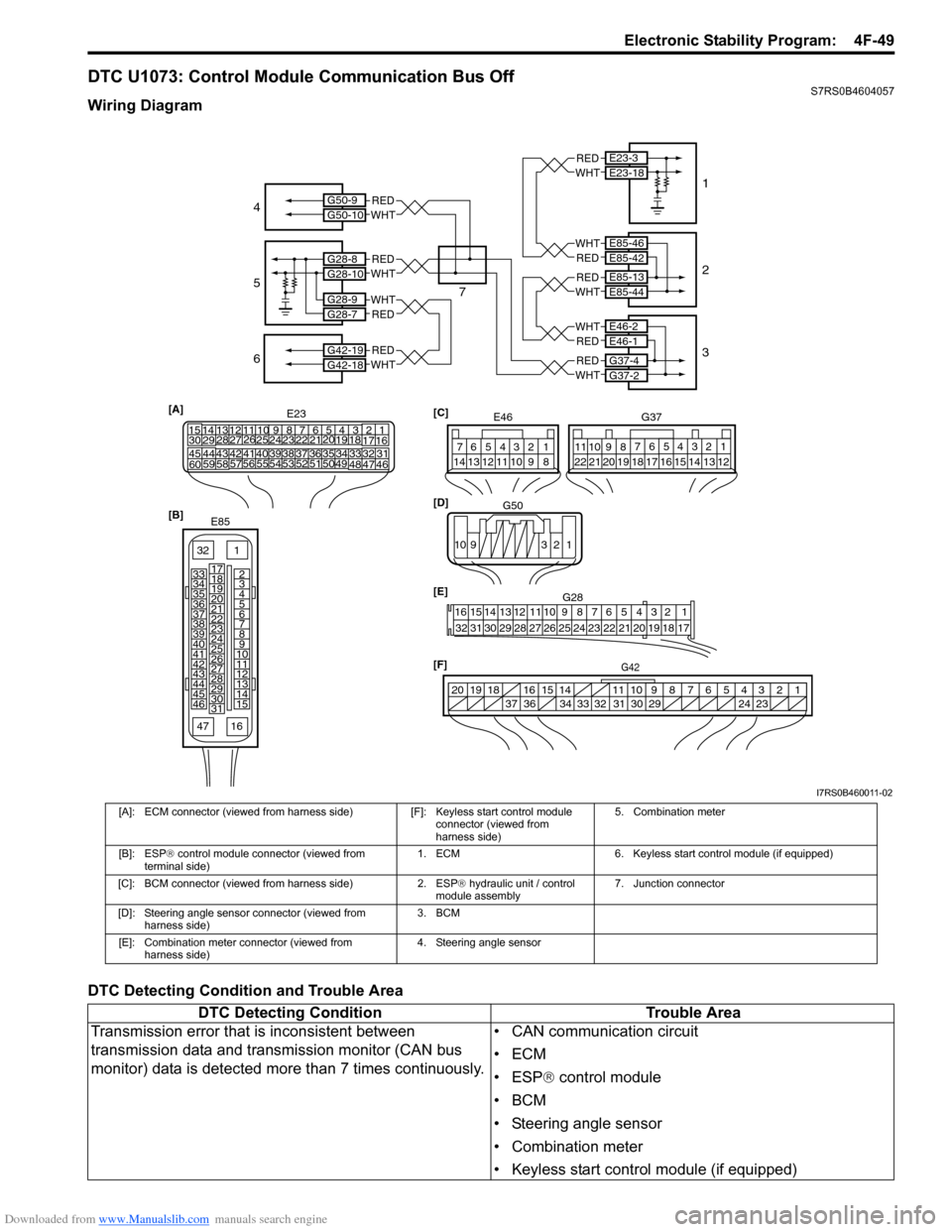
DTC U1073: Control Module Communication Bus OffS7RS0B4604057
Wiring Diagram
DTC Detecting Condition and Trouble Area
E85-13E85-44
E46-2E46-1
G37-4G37-2
E85-46E85-42
E23-3E23-18
G50-9G50-10
G28-8G28-10
G28-9G28-7
G42-19G42-18
REDWHT
WHTRED
WHTRED
REDWHT
REDWHT
WHTRED
REDWHT
REDWHT
REDWHT
[A]
21
E2334
1819
5671011
17
20
47 46
495051
2122
52 16
25 9
24
14
29
5557 54 53
59
60 5826
27
28
15
30
56 4832 31343536374042 39 38
44
45 43 41 33
1213
238
G42[F]
1234567891011
141516
36 34 33 32 31 30 29 24 23
37
181920
[B]
E85
161
15
2
3
4
5
6
7
8
9
10
11
12
13
14
17
18
19
20
21
22
23
24
25
26
27
28
29
30
31
3233
34
35
36
37
38
39
40
41
42
43
44
45
46
47 [C]
G37
E46
124
53
67
891011121314124
53
67
891011
1213141516171819202122
[E] G28
12345678910111213141516
17181920212223242526272829303132
[D] G50
109 321
4
5
7 1
2
3
6
I7RS0B460011-02
[A]: ECM connector (viewed from harness side) [F]: Keyless start control module
connector (viewed from
harness side) 5. Combination meter
[B]: ESP ® control module connector (viewed from
terminal side) 1. ECM
6. Keyless start control module (if equipped)
[C]: BCM connector (viewed from harness side) 2. ESP® hydraulic unit / control
module assembly 7. Junction connector
[D]: Steering angle sensor connector (viewed from harness side) 3. BCM
[E]: Combination meter connector (viewed from harness side) 4. Steering angle sensor
DTC Detecting Condition
Trouble Area
Transmission error that is inconsistent between
transmission data and transmission monitor (CAN bus
monitor) data is detected more than 7 times continuously. • CAN communication circuit
•ECM
• ESP
® control module
•BCM
• Steering angle sensor
• Combination meter
• Keyless start control module (if equipped)
Page 624 of 1496
Downloaded from www.Manualslib.com manuals search engine 4F-50 Electronic Stability Program:
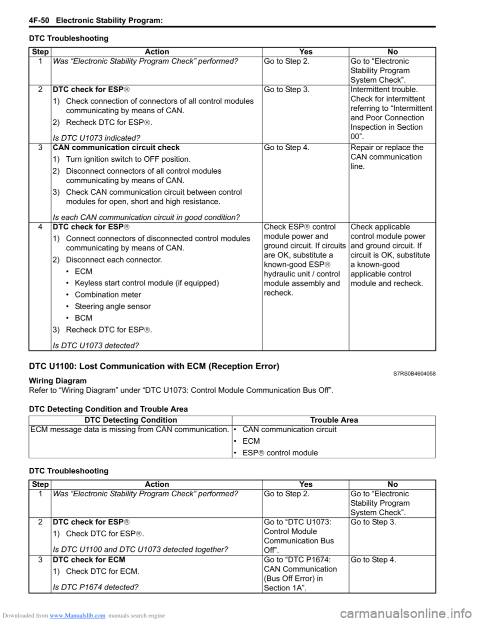
DTC Troubleshooting
DTC U1100: Lost Communication with ECM (Reception Error)S7RS0B4604058
Wiring Diagram
Refer to “Wiring Diagram” under “DTC U1073: Control Module Communication Bus Off”.
DTC Detecting Condition and Trouble Area
DTC TroubleshootingStep Action Yes No
1 Was “Electronic Stability Pr ogram Check” performed? Go to Step 2. Go to “Electronic
Stability Program
System Check”.
2 DTC check for ESP®
1) Check connection of connectors of all control modules
communicating by means of CAN.
2) Recheck DTC for ESP ®.
Is DTC U1073 indicated? Go to Step 3. Intermittent trouble.
Check for intermittent
referring to “Intermittent
and Poor Connection
Inspection in Section
00”.
3 CAN communication circuit check
1) Turn ignition switch to OFF position.
2) Disconnect connectors of all control modules
communicating by means of CAN.
3) Check CAN communication circuit between control modules for open, short and high resistance.
Is each CAN communication circuit in good condition? Go to Step 4. Repair or replace the
CAN communication
line.
4 DTC check for ESP®
1) Connect connectors of disconnected control modules
communicating by means of CAN.
2) Disconnect each connector. •ECM
• Keyless start control module (if equipped)
• Combination meter
• Steering angle sensor
•BCM
3) Recheck DTC for ESP ®.
Is DTC U1073 detected? Check ESP
® control
module power and
ground circuit. If circuits
are OK, substitute a
known-good ESP ®
hydraulic unit / control
module assembly and
recheck. Check applicable
control module power
and ground circuit. If
circuit is OK, substitute
a known-good
applicable control
module and recheck.
DTC Detecting Condition
Trouble Area
ECM message data is missing from CAN communication. • CAN communication circuit
•ECM
• ESP® control module
Step Action YesNo
1 Was “Electronic Stability Pr ogram Check” performed? Go to Step 2.Go to “Electronic
Stability Program
System Check”.
2 DTC check for ESP®
1) Check DTC for ESP ®.
Is DTC U1100 and DTC U1073 detected together? Go to “DTC U1073:
Control Module
Communication Bus
Off”.Go to Step 3.
3 DTC check for ECM
1) Check DTC for ECM.
Is DTC P1674 detected? Go to “DTC P1674:
CAN Communication
(Bus Off Error) in
Section 1A”.Go to Step 4.
Page 625 of 1496
Downloaded from www.Manualslib.com manuals search engine Electronic Stability Program: 4F-51
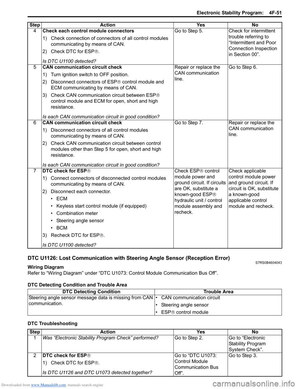
DTC U1126: Lost Communication with Steering Angle Sensor (Reception Error)S7RS0B4604043
Wiring Diagram
Refer to “Wiring Diagram” under “DTC U1073: Control Module Communication Bus Off”.
DTC Detecting Condition and Trouble Area
DTC Troubleshooting4
Check each control module connectors
1) Check connection of connectors of all control modules
communicating by means of CAN.
2) Check DTC for ESP ®.
Is DTC U1100 detected? Go to Step 5. Check for intermittent
trouble referring to
“Intermittent and Poor
Connection Inspection
in Section 00”.
5 CAN communication circuit check
1) Turn ignition switch to OFF position.
2) Disconnect connectors of ESP ® control module and
ECM communicating by means of CAN.
3) Check CAN communication circuit between ESP®
control module and ECM for open, short and high
resistance.
Is each CAN communication circuit in good condition? Repair or replace the
CAN communication
line.
Go to Step 6.
6 CAN communication circuit check
1) Disconnect connectors of all control modules
communicating by means of CAN.
2) Check CAN communication circuit between control modules other than Step 5 for open, short and high
resistance.
Is each CAN communication circuit in good condition? Go to Step 7. Repair or replace the
CAN communication
line.
7 DTC check for ESP®
1) Connect connectors of disconnected control modules
communicating by means of CAN.
2) Disconnect each connector. •ECM
• Keyless start control module (if equipped)
• Combination meter
• Steering angle sensor
•BCM
3) Recheck DTC for ESP ®.
Is DTC U1100 detected? Check ESP
® control
module power and
ground circuit. If circuits
are OK, substitute a
known-good ESP ®
hydraulic unit / control
module assembly and
recheck. Check applicable
control module power
and ground circuit. If
circuit is OK, substitute
a known-good
applicable control
module and recheck.
Step Action Yes No
DTC Detecting Condition
Trouble Area
Steering angle sensor message data is missing from CAN
communication. • CAN communication circuit
• Steering angle sensor
• ESP
® control module
Step Action YesNo
1 Was “Electronic Stability Pr ogram Check” performed? Go to Step 2.Go to “Electronic
Stability Program
System Check”.
2 DTC check for ESP®
1) Check DTC for ESP ®.
Is DTC U1126 and DTC U1073 detected together? Go to “DTC U1073:
Control Module
Communication Bus
Off”.Go to Step 3.
Page 626 of 1496
Downloaded from www.Manualslib.com manuals search engine 4F-52 Electronic Stability Program:
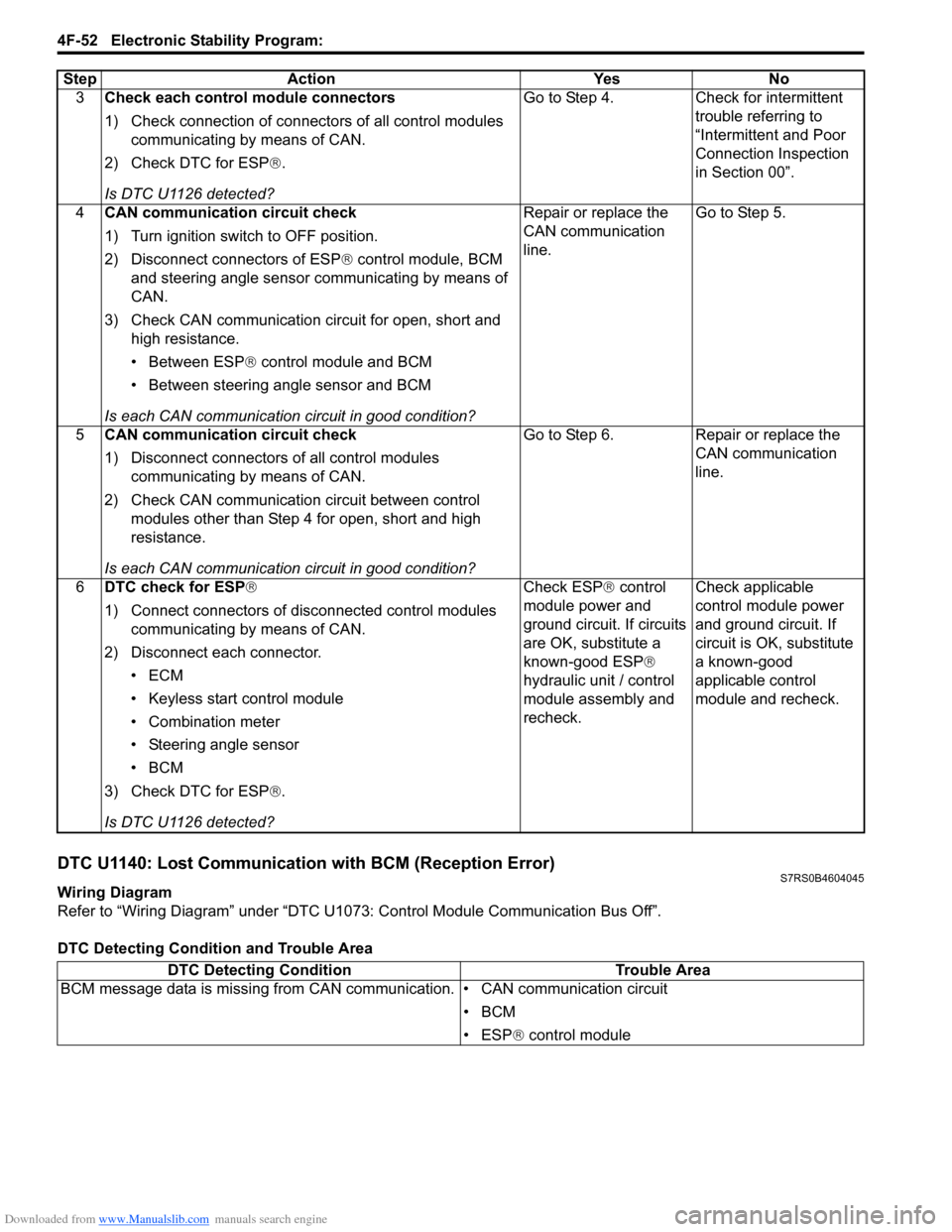
DTC U1140: Lost Communication with BCM (Reception Error)S7RS0B4604045
Wiring Diagram
Refer to “Wiring Diagram” under “DTC U1073: Control Module Communication Bus Off”.
DTC Detecting Condition and Trouble Area3
Check each control module connectors
1) Check connection of connectors of all control modules
communicating by means of CAN.
2) Check DTC for ESP ®.
Is DTC U1126 detected? Go to Step 4. Check for intermittent
trouble referring to
“Intermittent and Poor
Connection Inspection
in Section 00”.
4 CAN communication circuit check
1) Turn ignition switch to OFF position.
2) Disconnect connectors of ESP ® control module, BCM
and steering angle sensor communicating by means of
CAN.
3) Check CAN communication circuit for open, short and high resistance.
• Between ESP ® control module and BCM
• Between steering angle sensor and BCM
Is each CAN communication circuit in good condition? Repair or replace the
CAN communication
line.
Go to Step 5.
5 CAN communication circuit check
1) Disconnect connectors of all control modules
communicating by means of CAN.
2) Check CAN communication circuit between control modules other than Step 4 for open, short and high
resistance.
Is each CAN communication circuit in good condition? Go to Step 6. Repair or replace the
CAN communication
line.
6 DTC check for ESP®
1) Connect connectors of disconnected control modules
communicating by means of CAN.
2) Disconnect each connector. •ECM
• Keyless start control module
• Combination meter
• Steering angle sensor
•BCM
3) Check DTC for ESP ®.
Is DTC U1126 detected? Check ESP
® control
module power and
ground circuit. If circuits
are OK, substitute a
known-good ESP ®
hydraulic unit / control
module assembly and
recheck. Check applicable
control module power
and ground circuit. If
circuit is OK, substitute
a known-good
applicable control
module and recheck.
Step Action Yes No
DTC Detecting Condition
Trouble Area
BCM message data is missing from CAN communication. • CAN communication circuit
•BCM
• ESP® control module
Page 641 of 1496
Downloaded from www.Manualslib.com manuals search engine Table of Contents 5- i
5
Section 5
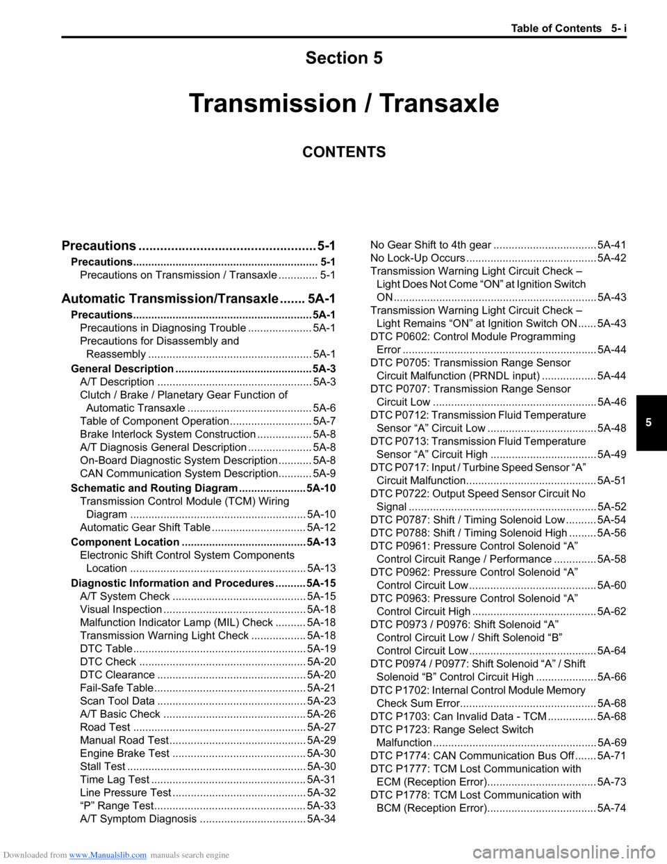
CONTENTS
Transmission / Transaxle
Precautions ................................................. 5-1
Precautions............................................................. 5-1
Precautions on Transmission / Transaxle ............. 5-1
Automatic Transmission/Transaxle ....... 5A-1
Precautions........................................................... 5A-1Precautions in Diagnosing Trouble ..................... 5A-1
Precautions for Disassembly and Reassembly ...................................................... 5A-1
General Description ............................................. 5A-3 A/T Description ................................................... 5A-3
Clutch / Brake / Planetary Gear Function of Automatic Transaxle ......................................... 5A-6
Table of Component Operation ........................... 5A-7
Brake Interlock System Construction .................. 5A-8
A/T Diagnosis General Description ..................... 5A-8
On-Board Diagnostic System Description ........... 5A-8
CAN Communication System Description........... 5A-9
Schematic and Routing Diagram ...................... 5A-10 Transmission Control Module (TCM) Wiring
Diagram .......................................................... 5A-10
Automatic Gear Shift Table ............................... 5A-12
Component Locatio n ......................................... 5A-13
Electronic Shift Cont rol System Components
Location .......................................................... 5A-13
Diagnostic Information and Procedures .......... 5A-15 A/T System Check ............................................ 5A-15
Visual Inspection ............................................... 5A-18
Malfunction Indicator Lamp (MIL) Check .......... 5A-18
Transmission Warning Ligh t Check .................. 5A-18
DTC Table ......................................................... 5A-19
DTC Check ....................................................... 5A-20
DTC Clearance ................................................. 5A-20
Fail-Safe Table ................ .................................. 5A-21
Scan Tool Data ................................................. 5A-23
A/T Basic Check ............................................... 5A-26
Road Test ......................................................... 5A-27
Manual Road Test ........... .................................. 5A-29
Engine Brake Test ............................................ 5A-30
Stall Test ........................................................... 5A-30
Time Lag Test ................................................... 5A-31
Line Pressure Test .......... .................................. 5A-32
“P” Range Test.................................................. 5A-33
A/T Symptom Diagnosis ..... .............................. 5A-34 No Gear Shift to 4th gear .................................. 5A-41
No Lock-Up Occurs ........................................... 5A-42
Transmission Warning Light Circuit Check –
Light Does Not Come “ON” at Ignition Switch
ON ................................................................... 5A-43
Transmission Warning Light Circuit Check – Light Remains “ON” at Ignition Switch ON ...... 5A-43
DTC P0602: Control Module Programming Error ................................................................ 5A-44
DTC P0705: Transmission Range Sensor Circuit Malfunction (PRNDL input) .................. 5A-44
DTC P0707: Transmission Range Sensor Circuit Low ...................................................... 5A-46
DTC P0712: Transmission Fluid Temperature Sensor “A” Circuit Low ... ................................. 5A-48
DTC P0713: Transmission Fluid Temperature Sensor “A” Circuit High .. ................................. 5A-49
DTC P0717: Input / Turbine Speed Sensor “A” Circuit Malfunction........................................... 5A-51
DTC P0722: Output Speed Sensor Circuit No Signal .............................................................. 5A-52
DTC P0787: Shift / Timing Solenoid Low .......... 5A-54
DTC P0788: Shift / Timing Solenoid High ......... 5A-56
DTC P0961: Pressure Control Solenoid “A”
Control Circuit Range / Performance .............. 5A-58
DTC P0962: Pressure Control Solenoid “A”
Control Circuit Low .......................................... 5A-60
DTC P0963: Pressure Control Solenoid “A”
Control Circuit High ......................................... 5A-62
DTC P0973 / P0976: Shift Solenoid “A” Control Circuit Low / Shift Solenoid “B”
Control Circuit Low .......................................... 5A-64
DTC P0974 / P0977: Shift Solenoid “A” / Shift Solenoid “B” Control Circuit High .................... 5A-66
DTC P1702: Internal Co ntrol Module Memory
Check Sum Error............................................. 5A-68
DTC P1703: Can Invalid Data - TCM ................ 5A-68
DTC P1723: Range Select Switch Malfunction ...................................................... 5A-69
DTC P1774: CAN Communication Bus Off ....... 5A-71
DTC P1777: TCM Lost Communication with ECM (Reception Error).................................... 5A-73
DTC P1778: TCM Lost Communication with BCM (Reception Error).................................... 5A-74
Page 654 of 1496
Downloaded from www.Manualslib.com manuals search engine 5A-10 Automatic Transmission/Transaxle:
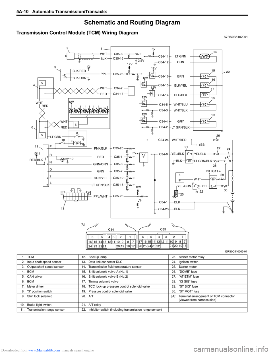
Schematic and Routing Diagram
Transmission Control Module (TCM) Wiring DiagramS7RS0B5102001
IG1
115
5
5
8
9
10 7
P
R
N
D
2
L
12
12V 2.5V
5V
12V
5V
12V
12V
12V
12V
WHT
BLK
BLK
BLK
BLK
PPLBLK/RED
BLK/ORN
IG11
RED/BLK
YEL/BLKYEL/BLU
LT GRN/BLK
+BB
WHT/RED
14
20
15
16
17
19
12V18
1
2
3
4
6
13 21
26
24
27
28 29
30
WHT
WHT
RED
RED
WHT
RED
65
16 15 14 13 12 11 43
24 23 2122 10 9 8 721
1920 18 17
C34
17 16
26 25
15 14
65 3
42
13 12
23 2224 11 10 9
21 20 19 87
18
1
C35
[A]
22
25
YELYEL/GRN
WHT
P
N
BRN
LT GRN
ORN
BLK/YEL
BLU/BLK
GRY
LT GRN/BLK WHT/BLU
WHT/BLK
C34-11
C34-12
C34-16
C34-15
C34-14
C34-4
C34-2
C34-1
C34-23 C34-6
C34-24 C34-5
C34-3
RED
GRN
GRN/ORN PNK/BLK
GRN/YEL
LT GRN/BLKC35-6
C35-16
C35-23 C35-25
C35-20
C35-1
C35-8
C35-7
C35-19
C35-18 C34-17 C34-7
4IG11
12V
23
PPL/WHT
LT GRN
I6RS0C510005-01
1. TCM 12. Backup lamp 23. Starter motor relay
2. Input shaft speed sensor 13. Data link connector DLC 24. Ignition switch
3. Output shaft speed sensor 14. Transmission fluid temperature sensor 25. Starter motor
4. ECM 15. Shift solenoid valve-A (No.1) 26. “DOME” fuse
5. CAN driver 16. Shift solenoid valve-B (No.2) 27. “AT ETM” fuse
6. BCM 17. Timing solenoid valve 28. “IG SIG” fuse
7. Meter driver 18. TCC lock-up pressure control solenoid valve 29. “ST SIG” fuse
8. “3” position switch 19. Pressure control solenoid valve 30. “ST MOT” fuse
9. Shift lock solenoid 20. A/T [A]: Terminal arrangement of TCM connector
(viewed from harness side)
10. Brake light switch 21. A/T relay
11. Transmission range sensor 22. Inhibitor switch (including transmission range sensor)
Page 688 of 1496
Downloaded from www.Manualslib.com manuals search engine 5A-44 Automatic Transmission/Transaxle:
DTC P0602: Control Module Programming ErrorS7RS0B5104048
System Description
Internal control module is installed in ECM.
DTC Detecting Condition and Trouble Area
DTC Confirmation Procedure 1) Connect scan tool to DLC with ignition switch turned OFF.
2) Clear DTC, pending DTC and freeze frame data by using scan tool.
3) Start engine and run it at idle if possible.
4) Check DTC.
DTC Troubleshooting
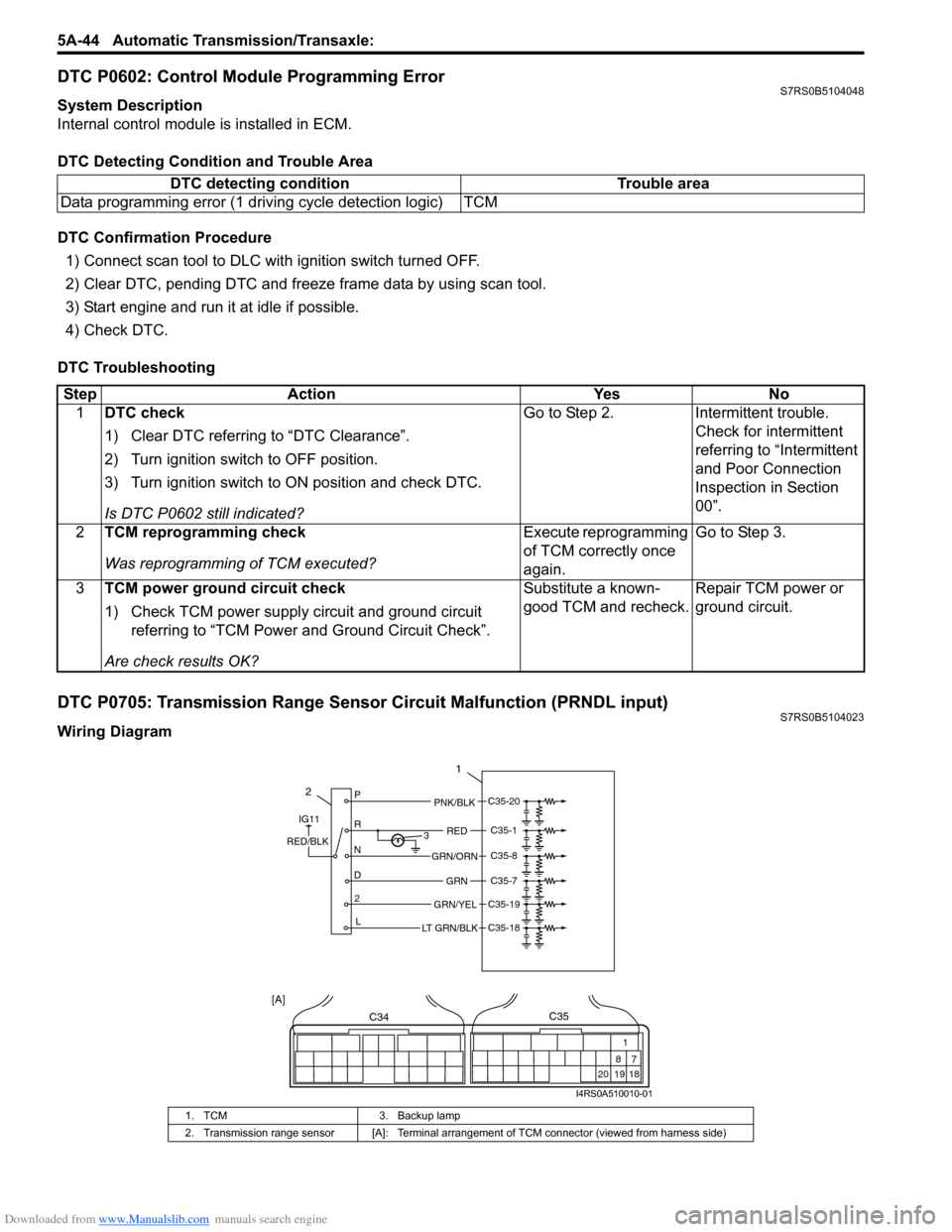
DTC P0705: Transmission Range Sensor Circuit Malfunction (PRNDL input)S7RS0B5104023
Wiring DiagramDTC detecting condition Trouble area
Data programming error (1 driving cycle detection logic) TCM
Step Action YesNo
1 DTC check
1) Clear DTC referring to “DTC Clearance”.
2) Turn ignition switch to OFF position.
3) Turn ignition switch to ON position and check DTC.
Is DTC P0602 still indicated? Go to Step 2.
Intermittent trouble.
Check for intermittent
referring to “Intermittent
and Poor Connection
Inspection in Section
00”.
2 TCM reprogramming check
Was reprogramming of TCM executed? Execute reprogramming
of TCM correctly once
again.Go to Step 3.
3 TCM power ground circuit check
1) Check TCM power supply circuit and ground circuit
referring to “TCM Power and Ground Circuit Check”.
Are check results OK? Substitute a known-
good TCM and recheck.
Repair TCM power or
ground circuit.
1. TCM
3. Backup lamp
2. Transmission range sensor [A]: Terminal arrangem ent of TCM connector (viewed from harness side)
2P
R
N
D 2 L 3
1
PNK/BLK
RED
GRN
GRN/ORN
GRN/YEL
IG11
RED/BLK
LT GRN/BLK
C35-20
C35-1
C35-8
C35-7
C35-19
C35-18
C34
20 19
87
18
1
C35
[A]
I4RS0A510010-01