Drive SUZUKI SWIFT 2008 2.G Service Manual Online
[x] Cancel search | Manufacturer: SUZUKI, Model Year: 2008, Model line: SWIFT, Model: SUZUKI SWIFT 2008 2.GPages: 1496, PDF Size: 34.44 MB
Page 417 of 1496
Downloaded from www.Manualslib.com manuals search engine Charging System: 1J-7
With Charging Equipment
CAUTION!
When jump starting engine with charging
equipment, be sure equipment used is 12-
volt and negative ground. Do not use 24-volt
charging equipment. Using such equipment
can cause serious damage to electrical
system or electronic parts.
Battery Dismounting and RemountingS7RS0B1A06002
WARNING!
When handling battery, following safety
precautions should be followed:
• Hydrogen gas is produced by battery. A flame or spark near battery may cause the
gas to ignite.
• Battery fluid is highly acidic. Avoid spilling on clothing or other fabric. Any spilled
electrolyte should be flushed with large
quantity of water and cleaned immediately.
Dismounting
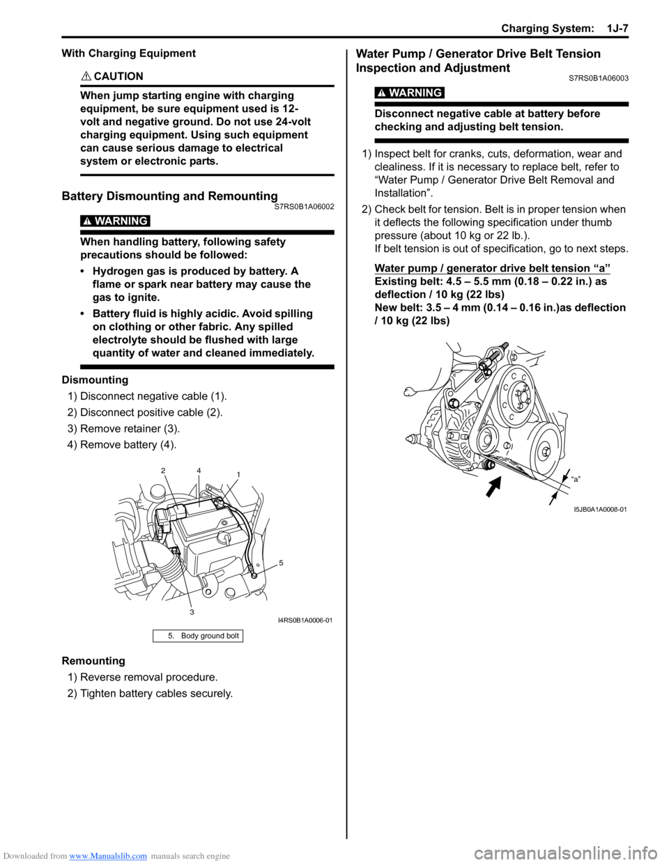
1) Disconnect negative cable (1).
2) Disconnect positive cable (2).
3) Remove retainer (3).
4) Remove battery (4).
Remounting 1) Reverse removal procedure.
2) Tighten battery cables securely.
Water Pump / Generator Drive Belt Tension
Inspection and Adjustment
S7RS0B1A06003
WARNING!
Disconnect negative cable at battery before
checking and adjusting belt tension.
1) Inspect belt for cranks, cuts, deformation, wear and clealiness. If it is necessary to replace belt, refer to
“Water Pump / Generator Drive Belt Removal and
Installation”.
2) Check belt for tension. Belt is in proper tension when it deflects the following specification under thumb
pressure (about 10 kg or 22 lb.).
If belt tension is out of spec ification, go to next steps.
Water pump / generator drive belt tension
“a”
Existing belt: 4.5 – 5.5 mm (0.18 – 0.22 in.) as
deflection / 10 kg (22 lbs)
New belt: 3.5 – 4 mm (0.14 – 0.16 in.)as deflection
/ 10 kg (22 lbs)
5. Body ground bolt
1
3 5
2
4
I4RS0B1A0006-01
“a”
I5JB0A1A0008-01
Page 418 of 1496
Downloaded from www.Manualslib.com manuals search engine 1J-8 Charging System:
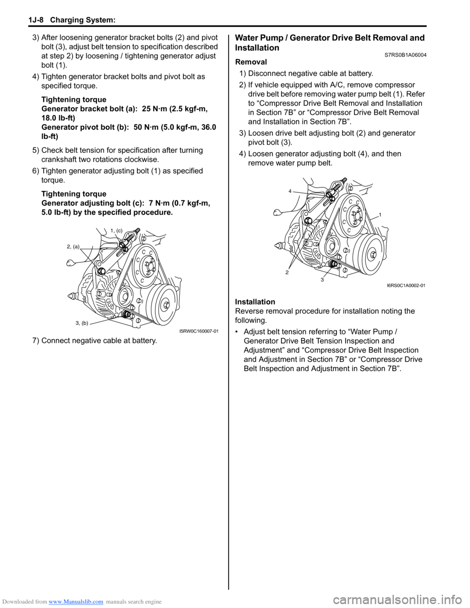
3) After loosening generator bracket bolts (2) and pivot bolt (3), adjust belt tensio n to specification described
at step 2) by loosening / tightening generator adjust
bolt (1).
4) Tighten generator bracket bolts and pivot bolt as specified torque.
Tightening torque
Generator bracket bolt (a): 25 N·m (2.5 kgf-m,
18.0 lb-ft)
Generator pivot bolt (b): 50 N·m (5.0 kgf-m, 36.0
lb-ft)
5) Check belt tension for specification after turning crankshaft two rotations clockwise.
6) Tighten generator adjusting bolt (1) as specified torque.
Tightening torque
Generator adjusting bolt (c): 7 N·m (0.7 kgf-m,
5.0 lb-ft) by the specified procedure.
7) Connect negative cable at battery.Water Pump / Generator Drive Belt Removal and
Installation
S7RS0B1A06004
Removal 1) Disconnect negative cable at battery.
2) If vehicle equipped with A/C, remove compressor drive belt before removing water pump belt (1). Refer
to “Compressor Drive Belt Removal and Installation
in Section 7B” or “Compr essor Drive Belt Removal
and Installation in Section 7B”.
3) Loosen drive belt adjusting bolt (2) and generator pivot bolt (3).
4) Loosen generator adjusting bolt (4), and then remove water pump belt.
Installation
Reverse removal procedure for installation noting the
following.
• Adjust belt tension referring to “Water Pump / Generator Drive Belt Tension Inspection and
Adjustment” and “Compressor Drive Belt Inspection
and Adjustment in Section 7B” or “Compressor Drive
Belt Inspection and Adjustment in Section 7B”.
1, (c)
2, (a)
3, (b)
I5RW0C160007-01
4
23
1
I6RS0C1A0002-01
Page 419 of 1496
Downloaded from www.Manualslib.com manuals search engine Charging System: 1J-9
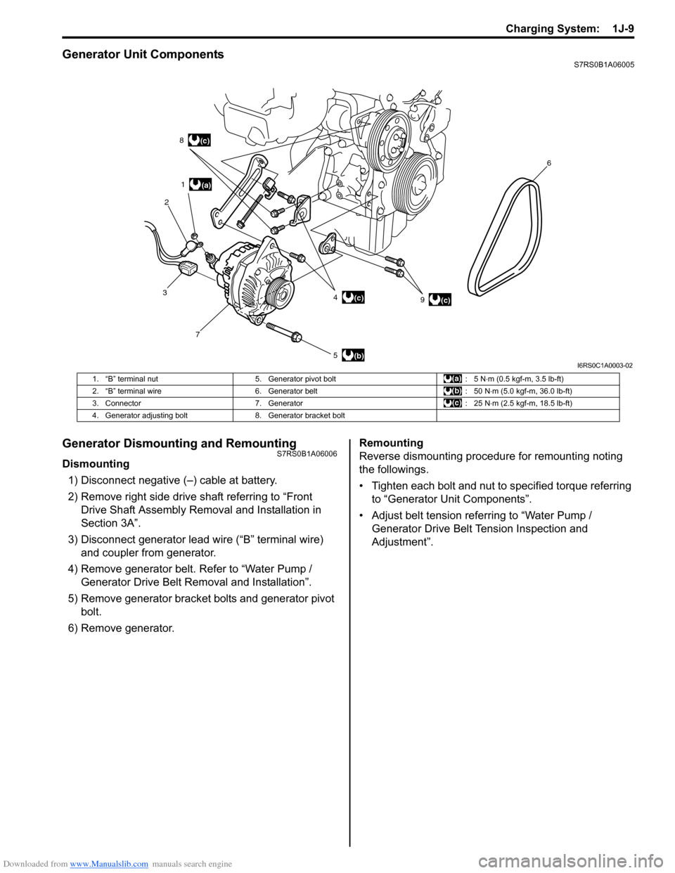
Generator Unit ComponentsS7RS0B1A06005
Generator Dismounting and RemountingS7RS0B1A06006
Dismounting1) Disconnect negative (–) cable at battery.
2) Remove right side drive shaft referring to “Front Drive Shaft Assembly Removal and Installation in
Section 3A”.
3) Disconnect generator lead wire (“B” terminal wire) and coupler from generator.
4) Remove generator belt. Refer to “Water Pump / Generator Drive Belt Re moval and Installation”.
5) Remove generator bracket bolts and generator pivot bolt.
6) Remove generator. Remounting
Reverse dismounting procedure for remounting noting
the followings.
• Tighten each bolt and nut to specified torque referring
to “Generator Unit Components”.
• Adjust belt tension referring to “Water Pump / Generator Drive Belt Tension Inspection and
Adjustment”.
(a)
(b)
(c)
1
2 8
3 7 5 49 6(c)
(c)
I6RS0C1A0003-02
1. “B” terminal nut
5. Generator pivot bolt : 5 N⋅m (0.5 kgf-m, 3.5 lb-ft)
2. “B” terminal wire 6. Generator belt : 50 N⋅m (5.0 kgf-m, 36.0 lb-ft)
3. Connector 7. Generator : 25 N⋅m (2.5 kgf-m, 18.5 lb-ft)
4. Generator adjusting bolt 8. Generator bracket bolt
Page 420 of 1496
Downloaded from www.Manualslib.com manuals search engine 1J-10 Charging System:
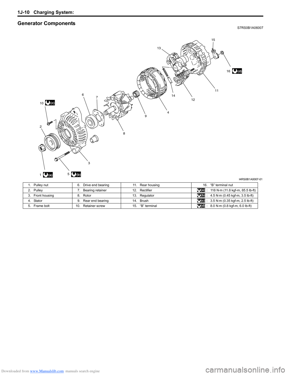
Generator ComponentsS7RS0B1A06007
1211
13
14
(a)(b)
(c)
(d)
1 2
3 4
56
7
89
10 15
16
I4RS0B1A0007-01
1. Pulley nut 6. Drive end bearing 11. Rear housing 16. “B” terminal nut
2. Pulley 7. Bearing retainer 12. Rectifier : 118 N⋅m (11.8 kgf-m, 85.5 lb-ft)
3. Front housing 8. Rotor 13. Regulator : 4.5 N⋅m (0.45 kgf-m, 3.5 lb-ft)
4. Stator 9. Rear end bearing 14. Brush : 3.5 N⋅m (0.35 kgf-m, 2.5 lb-ft)
5. Frame bolt 10. Retainer screw 15. “B” terminal : 8.0 N⋅m (0.8 kgf-m, 6.0 lb-ft)
Page 432 of 1496
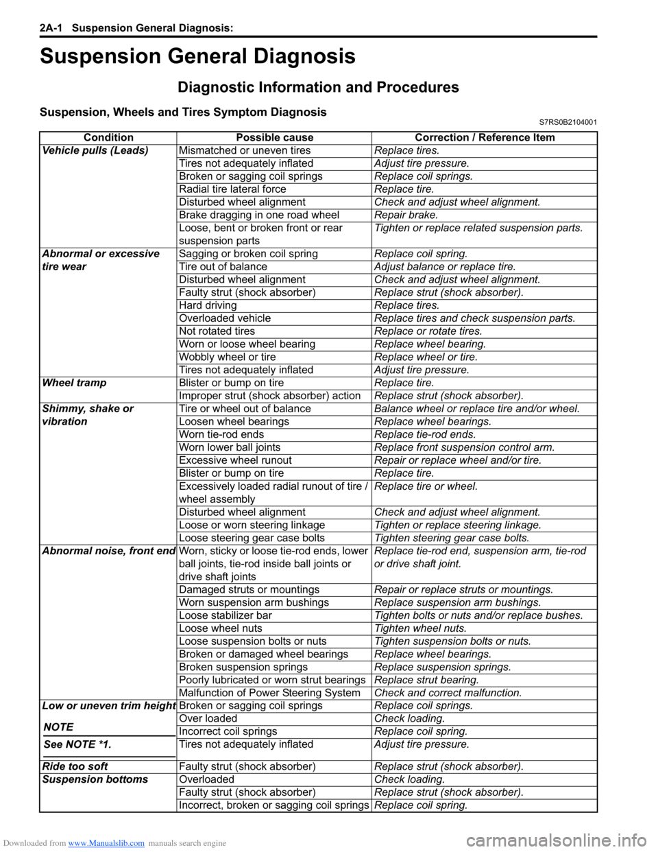
Downloaded from www.Manualslib.com manuals search engine 2A-1 Suspension General Diagnosis:
Suspension
Suspension General Diagnosis
Diagnostic Information and Procedures
Suspension, Wheels and Tires Symptom DiagnosisS7RS0B2104001
ConditionPossible cause Correction / Reference Item
Vehicle pulls (Leads) Mismatched or uneven tires Replace tires.
Tires not adequately inflated Adjust tire pressure.
Broken or sagging coil springs Replace coil springs.
Radial tire lateral force Replace tire.
Disturbed wheel alignment Check and adjust wheel alignment.
Brake dragging in one road wheel Repair brake.
Loose, bent or broken front or rear
suspension parts Tighten or replace related suspension parts.
Abnormal or excessive
tire wear Sagging or broken coil spring
Replace coil spring.
Tire out of balance Adjust balance or replace tire.
Disturbed wheel alignment Check and adjust wheel alignment.
Faulty strut (shock absorber) Replace strut (shock absorber).
Hard driving Replace tires.
Overloaded vehicle Replace tires and check suspension parts.
Not rotated tires Replace or rotate tires.
Worn or loose wheel bearing Replace wheel bearing.
Wobbly wheel or tire Replace wheel or tire.
Tires not adequately inflated Adjust tire pressure.
Wheel tramp Blister or bump on tire Replace tire.
Improper strut (shock absorber) action Replace strut (shock absorber).
Shimmy, shake or
vibration Tire or wheel out of balance
Balance wheel or replace tire and/or wheel.
Loosen wheel bearings Replace wheel bearings.
Worn tie-rod ends Replace tie-rod ends.
Worn lower ball joints Replace front suspension control arm.
Excessive wheel runout Repair or replace wheel and/or tire.
Blister or bump on tire Replace tire.
Excessively loaded radial runout of tire /
wheel assembly Replace tire or wheel.
Disturbed wheel alignment Check and adjust wheel alignment.
Loose or worn steering linkage Tighten or replace steering linkage.
Loose steering gear case bolts Tighten steering gear case bolts.
Abnormal noise, front end Worn, sticky or loose tie-rod ends, lower
ball joints, tie-rod in side ball joints or
drive shaft joints Replace tie-rod end, su
spension arm, tie-rod
or drive shaft joint.
Damaged struts or mountings Repair or replace struts or mountings.
Worn suspension arm bushings Replace suspension arm bushings.
Loose stabilizer bar Tighten bolts or nuts and/or replace bushes.
Loose wheel nuts Tighten wheel nuts.
Loose suspension bolts or nuts Tighten suspension bolts or nuts.
Broken or damaged wheel bearings Replace wheel bearings.
Broken suspension springs Replace suspension springs.
Poorly lubricated or worn strut bearings Replace strut bearing.
Malfunction of Power Steering System Check and correct malfunction.
Low or uneven trim height
NOTE
See NOTE *1.
Broken or sagging coil springs Replace coil springs.
Over loaded Check loading.
Incorrect coil springs Replace coil spring.
Tires not adequately inflated Adjust tire pressure.
Ride too soft Faulty strut (shock absorber) Replace strut (shock absorber).
Suspension bottoms Overloaded Check loading.
Faulty strut (shock absorber) Replace strut (shock absorber).
Incorrect, broken or sagging coil springs Replace coil spring.
Page 434 of 1496
Downloaded from www.Manualslib.com manuals search engine 2B-1 Front Suspension:
Suspension
Front Suspension
General Description
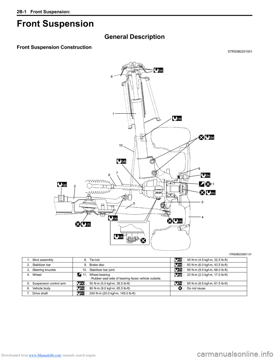
Front Suspension ConstructionS7RS0B2201001
I7RS0B220001-01
1. Strut assembly8. Tie-rod : 45 N⋅m (4.5 kgf-m, 32.5 lb-ft)
2. Stabilizer bar 9. Brake disc : 60 N⋅m (6.0 kgf-m, 43.5 lb-ft)
3. Steering knuckle 10. Stabilizer bar joint : 95 N⋅m (9.5 kgf-m, 68.0 lb-ft)
4. Wheel 11. Wheel bearing
: Rubber seal side of bearing faces vehicle outside. : 23 N
⋅m (2.3 kgf-m, 17.0 lb-ft)
5. Suspension control arm : 50 N⋅m (5.0 kgf-m, 36.5 lb-ft) : 85 N⋅m (8.5 kgf-m, 61.5 lb-ft)
6. Vehicle body : 90 N⋅m (9.0 kgf-m, 65.5 lb-ft) : Do not reuse.
7. Drive shaft : 200 N⋅m (20.0 kgf-m, 145.0 lb-ft)
Page 441 of 1496
Downloaded from www.Manualslib.com manuals search engine Front Suspension: 2B-8
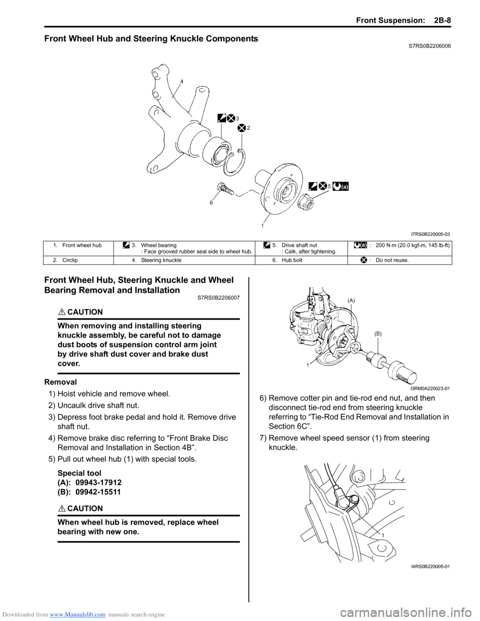
Front Wheel Hub and Steering Knuckle ComponentsS7RS0B2206006
Front Wheel Hub, Steering Knuckle and Wheel
Bearing Removal and Installation
S7RS0B2206007
CAUTION!
When removing and installing steering
knuckle assembly, be careful not to damage
dust boots of suspension control arm joint
by drive shaft dust cover and brake dust
cover.
Removal1) Hoist vehicle and remove wheel.
2) Uncaulk drive shaft nut.
3) Depress foot brake pedal and hold it. Remove drive shaft nut.
4) Remove brake disc referring to “Front Brake Disc Removal and Installa tion in Section 4B”.
5) Pull out wheel hub (1) with special tools.
Special tool
(A): 09943-17912
(B): 09942-15511
CAUTION!
When wheel hub is removed, replace wheel
bearing with new one.
6) Remove cotter pin and tie-rod end nut, and then disconnect tie-rod end from steering knuckle
referring to “Tie-Rod End Removal and Installation in
Section 6C”.
7) Remove wheel speed sensor (1) from steering knuckle.
I7RS0B220005-03
1. Front wheel hub 3. Wheel bearing
: Face grooved rubber seal side to wheel hub. 5. Drive shaft nut
: Calk, after tightening. : 200 N
⋅m (20.0 kgf-m, 145 lb-ft)
2. Circlip 4. Steering knuckle 6. Hub bolt: Do not reuse.
I3RM0A220023-01
1
I4RS0B220005-01
Page 443 of 1496
Downloaded from www.Manualslib.com manuals search engine Front Suspension: 2B-10
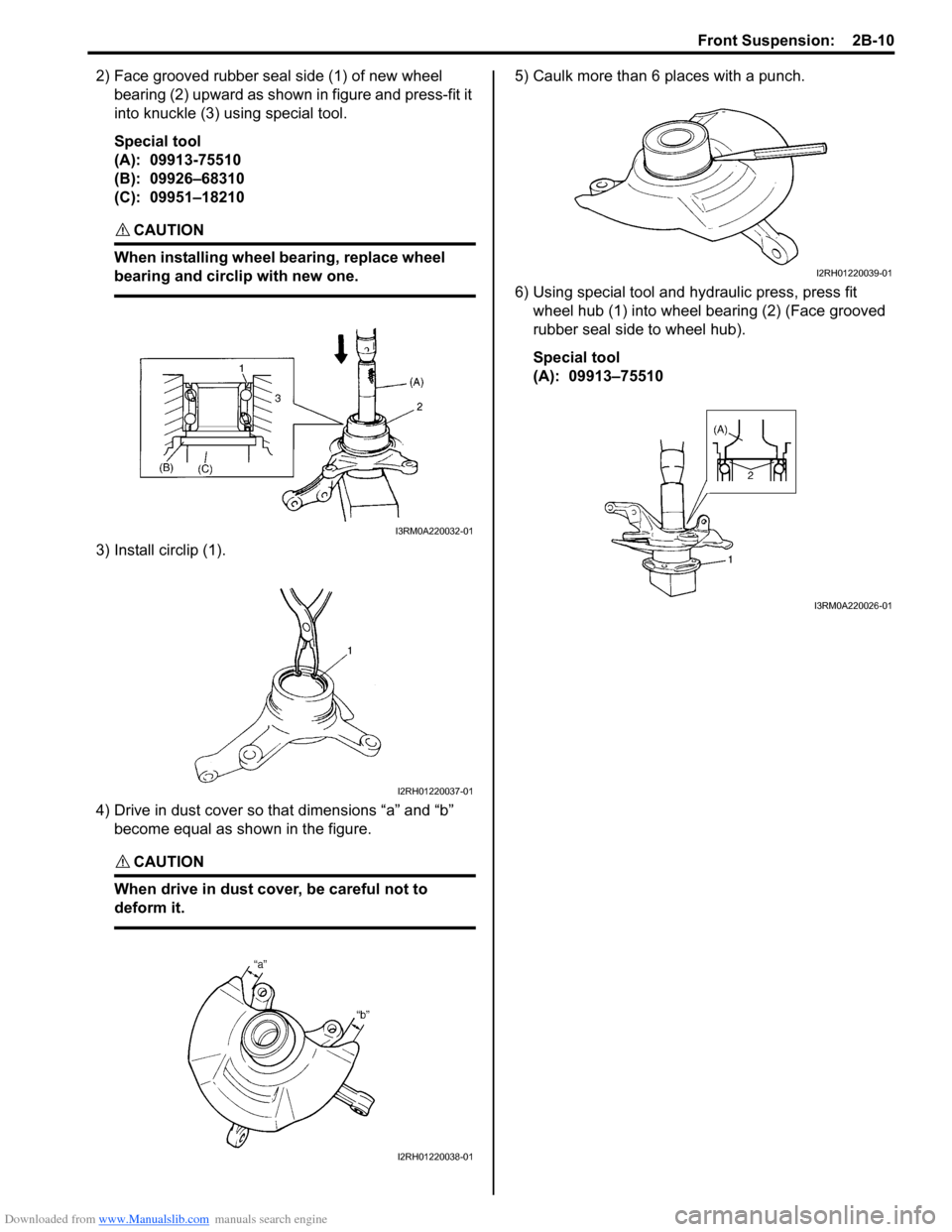
2) Face grooved rubber seal side (1) of new wheel bearing (2) upward as shown in figure and press-fit it
into knuckle (3) using special tool.
Special tool
(A): 09913-75510
(B): 09926–68310
(C): 09951–18210
CAUTION!
When installing wheel bearing, replace wheel
bearing and circlip with new one.
3) Install circlip (1).
4) Drive in dust cover so that dimensions “a” and “b” become equal as shown in the figure.
CAUTION!
When drive in dust cover, be careful not to
deform it.
5) Caulk more than 6 places with a punch.
6) Using special tool and hydraulic press, press fit
wheel hub (1) into wheel bearing (2) (Face grooved
rubber seal side to wheel hub).
Special tool
(A): 09913–75510
I3RM0A220032-01
I2RH01220037-01
I2RH01220038-01
I2RH01220039-01
I3RM0A220026-01
Page 444 of 1496
Downloaded from www.Manualslib.com manuals search engine 2B-11 Front Suspension:
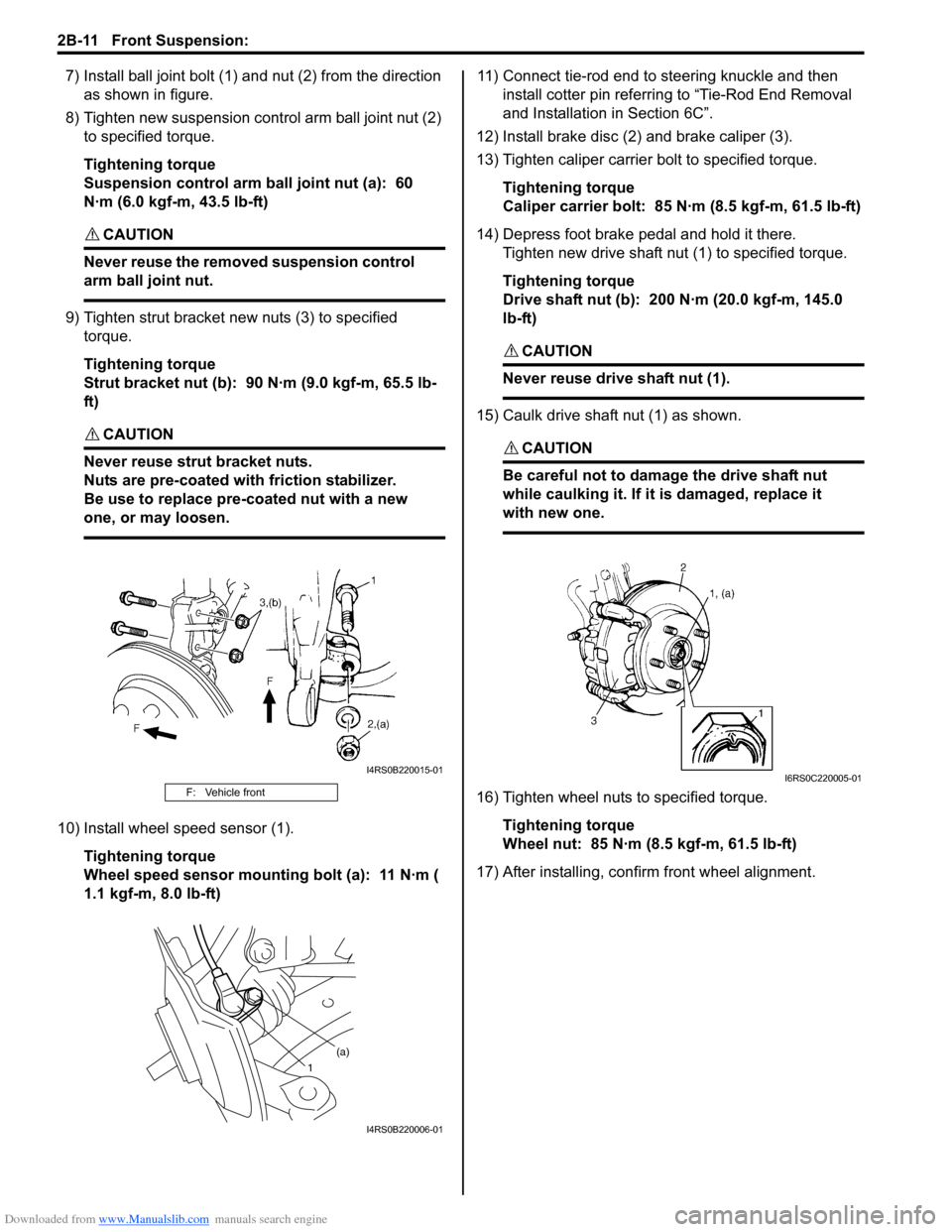
7) Install ball joint bolt (1) and nut (2) from the direction
as shown in figure.
8) Tighten new suspension co ntrol arm ball joint nut (2)
to specified torque.
Tightening torque
Suspension control arm ball joint nut (a): 60
N·m (6.0 kgf-m, 43.5 lb-ft)
CAUTION!
Never reuse the removed suspension control
arm ball joint nut.
9) Tighten strut bracket new nuts (3) to specified torque.
Tightening torque
Strut bracket nut (b): 90 N·m (9.0 kgf-m, 65.5 lb-
ft)
CAUTION!
Never reuse strut bracket nuts.
Nuts are pre-coated with friction stabilizer.
Be use to replace pre-coated nut with a new
one, or may loosen.
10) Install wheel speed sensor (1).
Tightening torque
Wheel speed sensor mounting bolt (a): 11 N·m (
1.1 kgf-m, 8.0 lb-ft) 11) Connect tie-rod end to steering knuckle and then
install cotter pin referrin g to “Tie-Rod End Removal
and Installation in Section 6C”.
12) Install brake disc (2) and brake caliper (3).
13) Tighten caliper carrier bolt to specified torque.
Tightening torque
Caliper carrier bolt: 85 N·m (8.5 kgf-m, 61.5 lb-ft)
14) Depress foot brake pedal and hold it there. Tighten new drive shaft nut (1) to specified torque.
Tightening torque
Drive shaft nut (b): 200 N·m (20.0 kgf-m, 145.0
lb-ft)
CAUTION!
Never reuse drive shaft nut (1).
15) Caulk drive shaft nut (1) as shown.
CAUTION!
Be careful not to damage the drive shaft nut
while caulking it. If it is damaged, replace it
with new one.
16) Tighten wheel nuts to specified torque.
Tightening torque
Wheel nut: 85 N·m (8.5 kgf-m, 61.5 lb-ft)
17) After installing, confirm front wheel alignment.F: Vehicle front
I4RS0B220015-01
1 (a)
I4RS0B220006-01
I6RS0C220005-01
Page 445 of 1496
Downloaded from www.Manualslib.com manuals search engine Front Suspension: 2B-12
Front Wheel Hub, Disc, Nut and Bearing CheckS7RS0B2206008
• Inspect each wheel disc for dents, distortion and cracks.
A disc in badly damaged condition must be replaced.
• Check rust of installation face inside of wheel disc.
As rust affects adversely, remove it thoroughly.
• Check wheel nuts for tightness and, as necessary, retighten them to specification.
• Check wheel bolt press-fitted into wheel hub for wear, damage, poor thread condition, and looseness.
Replace defective bolt with a new one.
When bolt installation is found loose, replace both bolt
and wheel hub with new ones.
Tightening torque
Wheel nut: 85 N·m (8.5 kgf-m, 61.5 lb-ft)
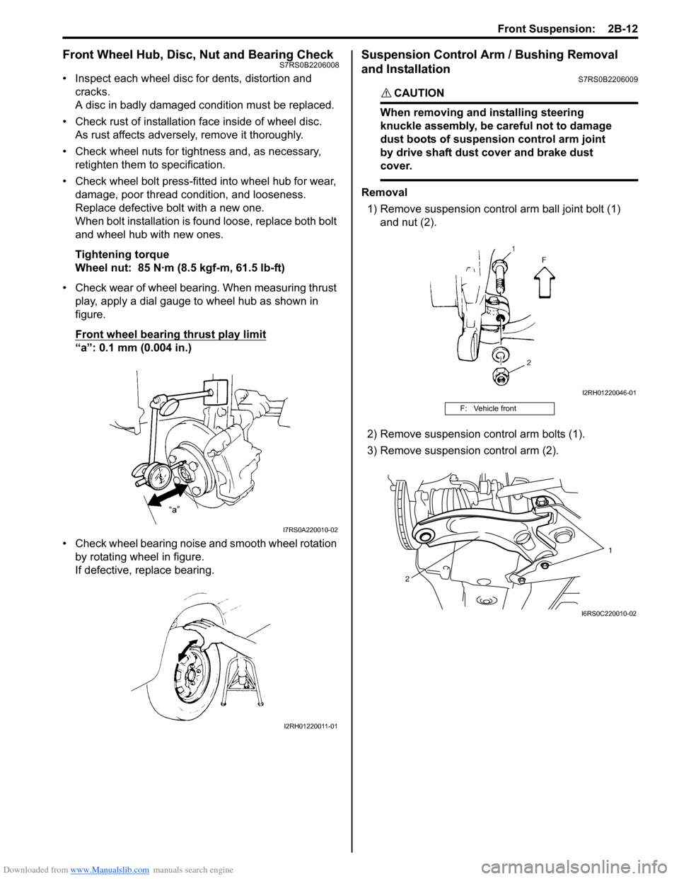
• Check wear of wheel bearing. When measuring thrust play, apply a dial gauge to wheel hub as shown in
figure.
Front wheel bearing thrust play limit
“a”: 0.1 mm (0.004 in.)
• Check wheel bearing noise and smooth wheel rotation by rotating wheel in figure.
If defective, replace bearing.
Suspension Control Arm / Bushing Removal
and Installation
S7RS0B2206009
CAUTION!
When removing and installing steering
knuckle assembly, be ca reful not to damage
dust boots of suspension control arm joint
by drive shaft dust cover and brake dust
cover.
Removal
1) Remove suspension contro l arm ball joint bolt (1)
and nut (2).
2) Remove suspension control arm bolts (1).
3) Remove suspension control arm (2).
I7RS0A220010-02
I2RH01220011-01
F: Vehicle front
I2RH01220046-01
1
2
I6RS0C220010-02