set SUZUKI SWIFT 2008 2.G Service Manual Online
[x] Cancel search | Manufacturer: SUZUKI, Model Year: 2008, Model line: SWIFT, Model: SUZUKI SWIFT 2008 2.GPages: 1496, PDF Size: 34.44 MB
Page 631 of 1496
Downloaded from www.Manualslib.com manuals search engine Electronic Stability Program: 4F-57
3) Remove front brake pipe referring to “Front Brake Hose / Pipe Removal and In stallation in Section 4A”.
4) Remove ESP ® hydraulic unit / control module with
bracket from vehicle by removing bracket bolts.
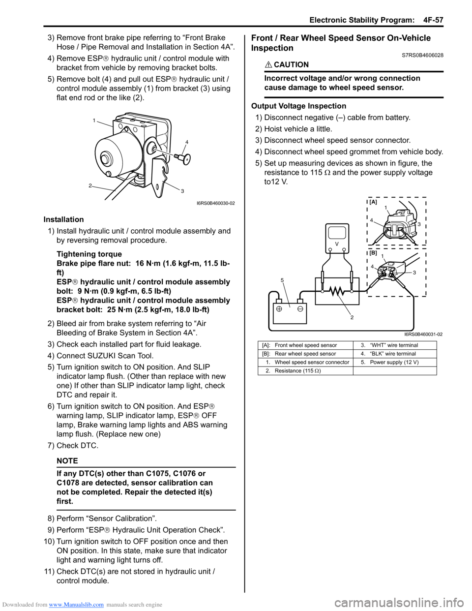
5) Remove bolt (4) and pull out ESP ® hydraulic unit /
control module assembly (1) from bracket (3) using
flat end rod or the like (2).
Installation 1) Install hydraulic unit / co ntrol module assembly and
by reversing removal procedure.
Tightening torque
Brake pipe flare nut: 16 N·m (1.6 kgf-m, 11.5 lb-
ft)
ESP ® hydraulic unit / control module assembly
bolt: 9 N·m (0.9 kgf-m, 6.5 lb-ft)
ESP ® hydraulic unit / control module assembly
bracket bolt: 25 N·m (2.5 kgf-m, 18.0 lb-ft)
2) Bleed air from brake system referring to “Air Bleeding of Brake System in Section 4A”.
3) Check each installed part for fluid leakage.
4) Connect SUZUKI Scan Tool.
5) Turn ignition switch to ON position. And SLIP indicator lamp flush. (Other than replace with new
one) If other than SLIP indicator lamp light, check
DTC and repair it.
6) Turn ignition switch to ON position. And ESP®
warning lamp, SLIP indicator lamp, ESP ® OFF
lamp, Brake warning lamp lights and ABS warning
lamp flush. (Replace new one)
7) Check DTC.
NOTE
If any DTC(s) other than C1075, C1076 or
C1078 are detected, sensor calibration can
not be completed. Repair the detected it(s)
first.
8) Perform “Sensor Calibration”.
9) Perform “ESP ® Hydraulic Unit Operation Check”.
10) Turn ignition switch to OFF position once and then
ON position. In this state, make sure that indicator
light and warning light turns off.
11) Check DTC(s) are not stored in hydraulic unit / control module.
Front / Rear Wheel Speed Sensor On-Vehicle
Inspection
S7RS0B4606028
CAUTION!
Incorrect voltage and/or wrong connection
cause damage to wheel speed sensor.
Output Voltage Inspection
1) Disconnect negative (–) cable from battery.
2) Hoist vehicle a little.
3) Disconnect wheel speed sensor connector.
4) Disconnect wheel speed grommet from vehicle body.
5) Set up measuring devices as shown in figure, the resistance to 115 Ω and the power supply voltage
to12 V.
4
1
2 3
I6RS0B460030-02
[A]: Front wheel speed sensor 3. “WHT” wire terminal
[B]: Rear wheel speed sensor 4. “BLK” wire terminal
1. Wheel speed sensor connector 5. Power supply (12 V)
2. Resistance (115 Ω)
V
2
5
4 1
3
43
1
[A]
[B]
I6RS0B460031-02
Page 646 of 1496
Downloaded from www.Manualslib.com manuals search engine 5A-2 Automatic Transmission/Transaxle:
CAUTION!
• Keep component parts in group for each subassembly and avoid mixing them up.
• Clean all parts with cleaning solvent thoroughly and air dry them.
• Use kerosene or automatic transaxle fluid as cleaning solvent.
• Do not use wiping cloths or rags to clean or dry parts.
• All oil passages should be blown out and checked to make sure that they are not
obstructed.
• Keep face and eyes away from solvent spray while air blowing parts.
• Check mating surface for irregularities and remove them, if any, and clean it again.
• Soak new clutch discs and brake discs in transaxle fluid for at least 2 hours before
assembly.
• Replace all gaskets and O-ring with new ones.
• Apply automatic transaxle fluid to all O- rings.
• When installing seal ring, be careful so that it is not expanded excessively, extruded or
caught.
• Replace oil seals that are removed and apply grease to their lips.
• Before installing, be sure to apply automatic transaxle fluid to sliding, rolling
and thrusting surface of all component
part. Also after installation, make sure to
check each part for proper operation.
• Always use torque wrench when tightening bolts.
• A new discs should be soaked in ATF at least 2 hours before use.
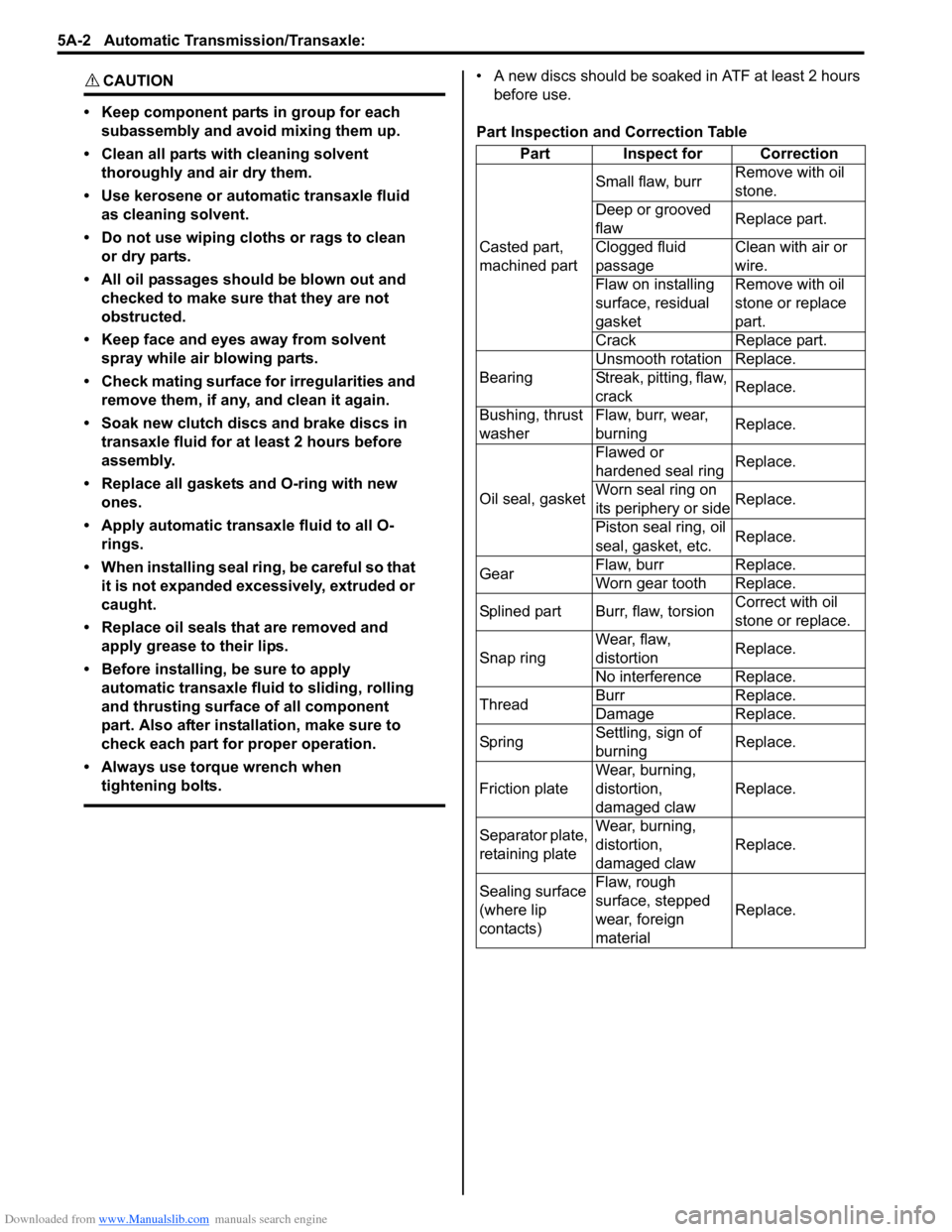
Part Inspection and Correction Table Part Inspect for Correction
Casted part,
machined part Small flaw, burr
Remove with oil
stone.
Deep or grooved
flaw Replace part.
Clogged fluid
passage Clean with air or
wire.
Flaw on installing
surface, residual
gasket Remove with oil
stone or replace
part.
Crack Replace part.
Bearing Unsmooth rotation Replace.
Streak, pitting, flaw,
crack
Replace.
Bushing, thrust
washer Flaw, burr, wear,
burning
Replace.
Oil seal, gasket Flawed or
hardened seal ring
Replace.
Worn seal ring on
its periphery or side Replace.
Piston seal ring, oil
seal, gasket, etc. Replace.
Gear Flaw, burr Replace.
Worn gear tooth Replace.
Splined part Burr, flaw, torsion Correct with oil
stone or replace.
Snap ring Wear, flaw,
distortion
Replace.
No interference Replace.
Thread Burr Replace.
Damage Replace.
Sp rin g Settling, sign of
burning Replace.
Friction plate Wear, burning,
distortion,
damaged claw Replace.
Separator plate,
retaining plate Wear, burning,
distortion,
damaged claw
Replace.
Sealing surface
(where lip
contacts) Flaw, rough
surface, stepped
wear, foreign
material
Replace.
Page 649 of 1496
Downloaded from www.Manualslib.com manuals search engine Automatic Transmission/Transaxle: 5A-5
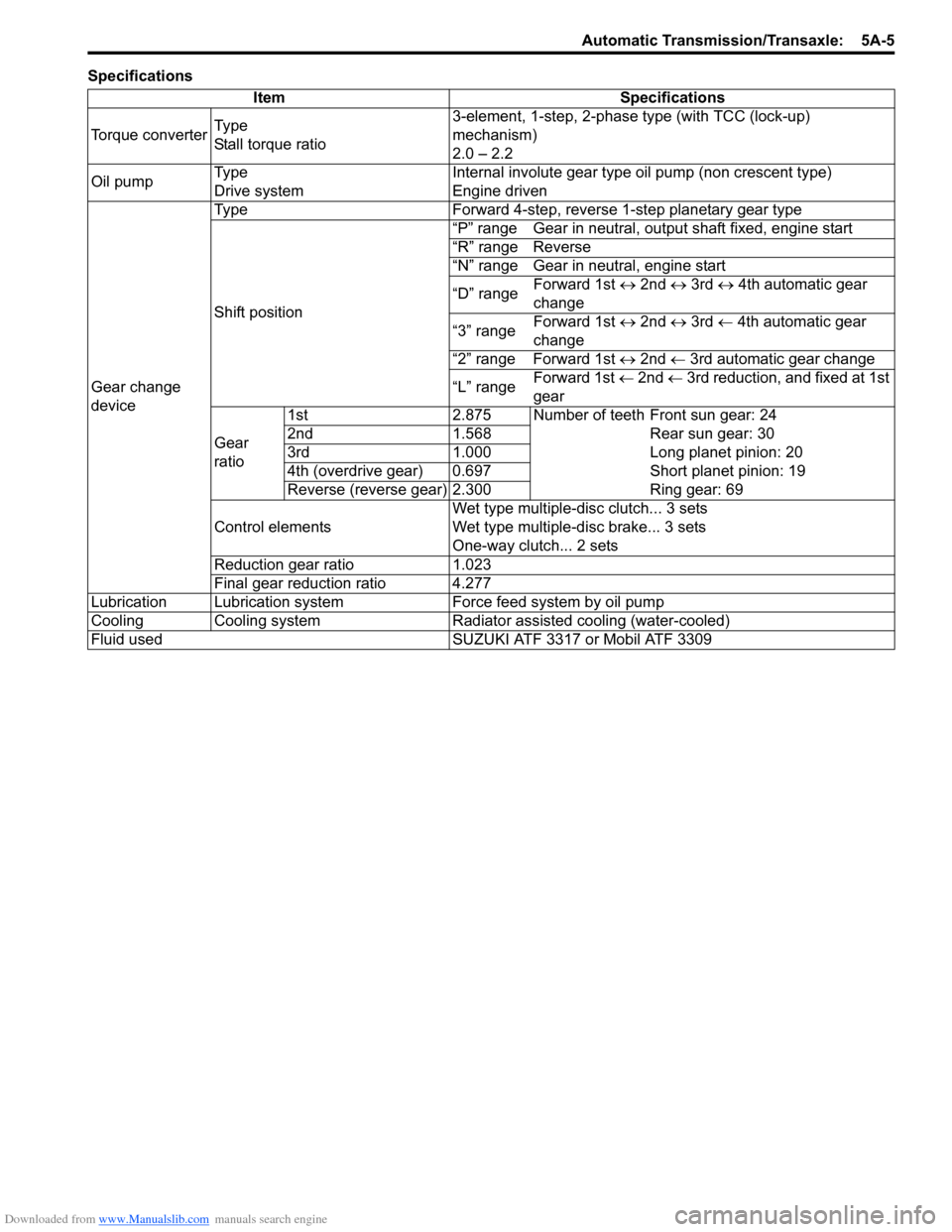
SpecificationsItem Specifications
Torque converter Ty p e
Stall torque ratio 3-element, 1-step, 2-phase type (with TCC (lock-up)
mechanism)
2.0 – 2.2
Oil pump Ty p e
Drive system Internal involute gear type oil pump (non crescent type)
Engine driven
Gear change
device Type Forward 4-step, reverse 1-step planetary gear type
Shift position
“P” range Gear in neutral, output shaft fixed, engine start
“R” range Reverse
“N” range Gear in neutral, engine start
“D” range
Forward 1st
↔ 2nd ↔ 3rd ↔ 4th automatic gear
change
“3” range Forward 1st
↔ 2nd ↔ 3rd ← 4th automatic gear
change
“2” range Forward 1st ↔ 2nd ← 3rd automatic gear change
“L” range Forward 1st
← 2nd ← 3rd reduction, and fixed at 1st
gear
Gear
ratio 1st 2.875 Number of teeth Front sun gear: 24
2nd 1.568 Rear sun gear: 30
3rd 1.000 Long planet pinion: 20
4th (overdrive gear) 0.697 Short planet pinion: 19
Reverse (reverse gear) 2.300 Ring gear: 69
Control elements Wet type multiple-disc clutch... 3 sets
Wet type multiple-d
isc brake... 3 sets
One-way clutch... 2 sets
Reduction gear ratio 1.023
Final gear reduction ratio 4.277
Lubrication Lubrication system Force feed system by oil pump
Cooling Cooling system Radiator assisted cooling (water-cooled)
Fluid used SUZUKI ATF 3317 or Mobil ATF 3309
Page 663 of 1496
Downloaded from www.Manualslib.com manuals search engine Automatic Transmission/Transaxle: 5A-19
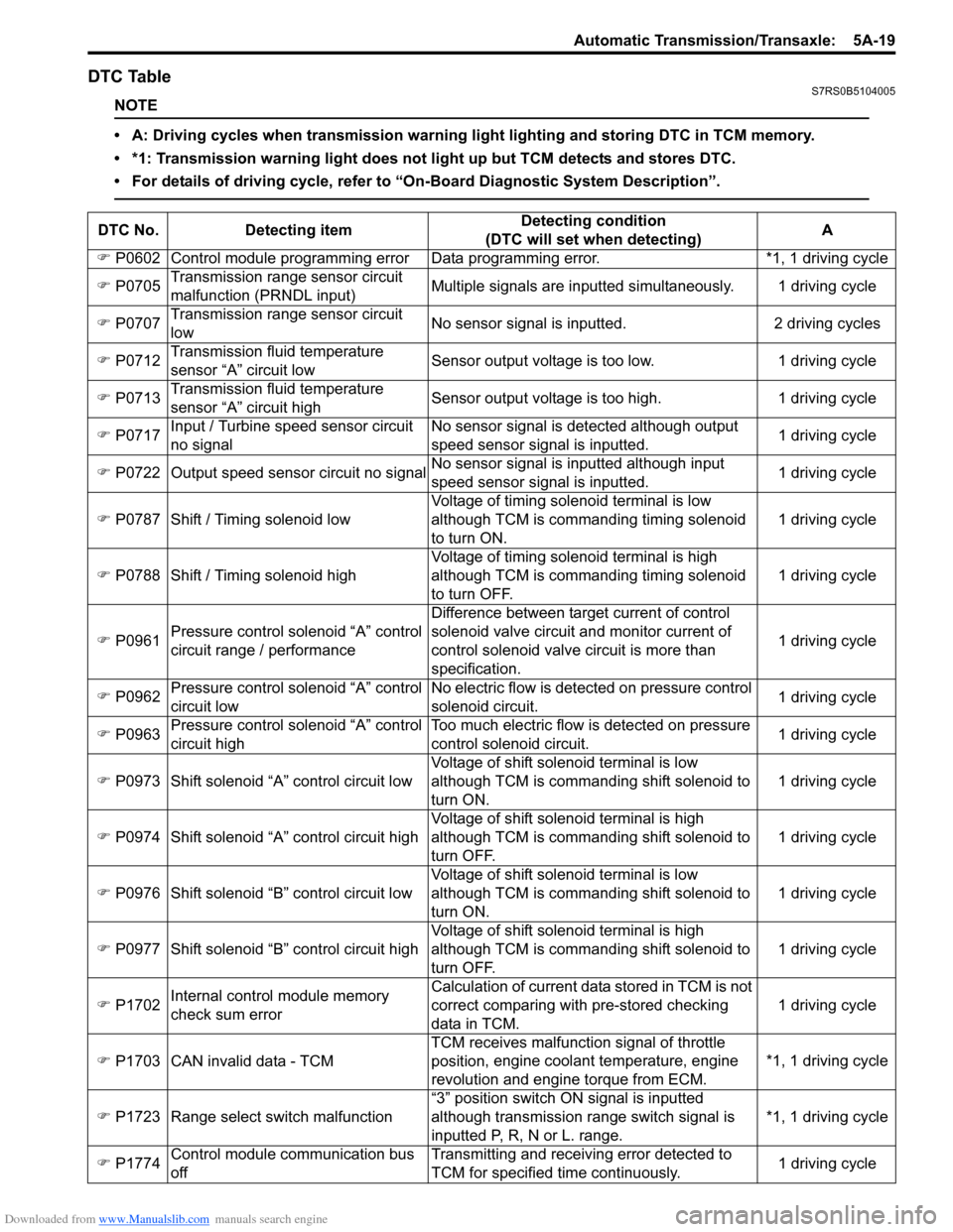
DTC TableS7RS0B5104005
NOTE
• A: Driving cycles when transmission warning light lighting and storing DTC in TCM memory.
• *1: Transmission warning light does not light up but TCM detects and stores DTC.
• For details of driving cycle, refer to “On-Board Diagnostic System Description”.
DTC No.Detecting item Detecting condition
(DTC will set when detecting) A
) P0602 Control module programming error D ata programming error. *1, 1 driving cycle
) P0705 Transmission range sensor circuit
malfunction (PRNDL input) Multiple signals are inputted
simultaneously. 1 driving cycle
) P0707 Transmission range sensor circuit
low No sensor signal is inputted.
2 driving cycles
) P0712 Transmission fluid temperature
sensor “A” circuit low Sensor output voltage is too low.
1 driving cycle
) P0713 Transmission fluid temperature
sensor “A” circuit high Sensor output voltage is too high.
1 driving cycle
) P0717 Input / Turbine speed sensor circuit
no signal No sensor signal is detected although output
speed sensor signal is inputted.
1 driving cycle
) P0722 Output speed sensor circuit no signal No sensor signal is inputted although input
speed sensor signal is inputted. 1 driving cycle
) P0787 Shift / Timing solenoid low Voltage of timing solenoid terminal is low
although TCM is commanding timing solenoid
to turn ON. 1 driving cycle
) P0788 Shift / Timing solenoid high Voltage of timing solenoid terminal is high
although TCM is commanding timing solenoid
to turn OFF. 1 driving cycle
) P0961 Pressure control solenoid “A” control
circuit range / performance Difference between target current of control
solenoid valve circuit and monitor current of
control solenoid valve circuit is more than
specification.
1 driving cycle
) P0962 Pressure control solenoid “A” control
circuit low No electric flow is detected on pressure control
solenoid circuit.
1 driving cycle
) P0963 Pressure control solenoid “A” control
circuit high Too much electric flow is detected on pressure
control solenoid circuit.
1 driving cycle
) P0973 Shift solenoid “A” control circuit low Voltage of shift solenoid terminal is low
although TCM is commanding shift solenoid to
turn ON. 1 driving cycle
) P0974 Shift solenoid “A” control circuit high Voltage of shift solenoid terminal is high
although TCM is commanding shift solenoid to
turn OFF. 1 driving cycle
) P0976 Shift solenoid “B” control circuit low Voltage of shift solenoid terminal is low
although TCM is commanding shift solenoid to
turn ON. 1 driving cycle
) P0977 Shift solenoid “B” control circuit high Voltage of shift solenoid terminal is high
although TCM is commanding shift solenoid to
turn OFF. 1 driving cycle
) P1702 Internal control module memory
check sum error Calculation of current data stored in TCM is not
correct comparing with pre-stored checking
data in TCM.
1 driving cycle
) P1703 CAN invalid data - TCM TCM receives malfunction signal of throttle
position
, engine coolan t temperature, engine
revolution and engine torque from ECM. *1, 1 driving cycle
) P1723 Range select switch malfunction “3” position switch ON signal is inputted
although transmission range switch signal is
inputted P, R, N or L. range. *1, 1 driving cycle
) P1774 Control module communication bus
off Transmitting and receiving error detected to
TCM for specified time continuously.
1 driving cycle
Page 664 of 1496
Downloaded from www.Manualslib.com manuals search engine 5A-20 Automatic Transmission/Transaxle:
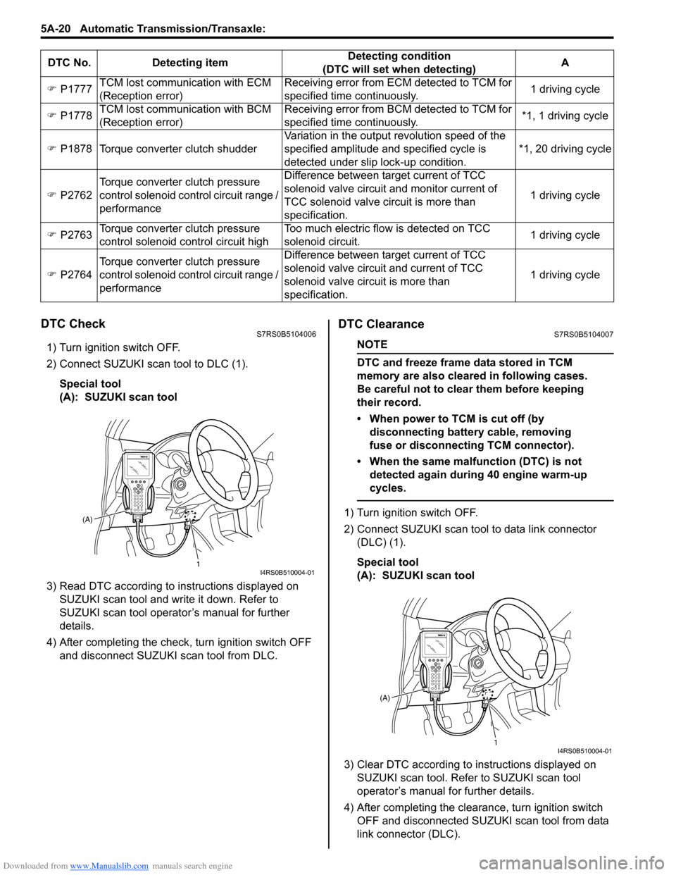
DTC CheckS7RS0B5104006
1) Turn ignition switch OFF.
2) Connect SUZUKI scan tool to DLC (1).
Special tool
(A): SUZUKI scan tool
3) Read DTC according to instructions displayed on SUZUKI scan tool and wr ite it down. Refer to
SUZUKI scan tool operator’s manual for further
details.
4) After completing the check, turn ignition switch OFF
and disconnect SUZUKI scan tool from DLC.
DTC ClearanceS7RS0B5104007
NOTE
DTC and freeze frame data stored in TCM
memory are also cleared in following cases.
Be careful not to clear them before keeping
their record.
• When power to TCM is cut off (by disconnecting battery cable, removing
fuse or disconnecting TCM connector).
• When the same malfunction (DTC) is not detected again during 40 engine warm-up
cycles.
1) Turn ignition switch OFF.
2) Connect SUZUKI scan tool to data link connector (DLC) (1).
Special tool
(A): SUZUKI scan tool
3) Clear DTC according to instructions displayed on SUZUKI scan tool. Refer to SUZUKI scan tool
operator’s manual for further details.
4) After completing the clearance, turn ignition switch OFF and disconnected SUZUKI scan tool from data
link connector (DLC).
)
P1777 TCM lost communication with ECM
(Reception error) Receiving error from ECM detected to TCM for
specified time continuously.
1 driving cycle
) P1778 TCM lost communication with BCM
(Reception error) Receiving error from BCM detected to TCM for
specified time continuously.
*1, 1 driving cycle
) P1878 Torque converter clutch shudder Variation in the output revolution speed of the
specified amplitude and specified cycle is
detected under slip lock-up condition. *1, 20 driving cycle
) P2762 Torque converter clutch pressure
control solenoid control circuit range /
performance Difference between target current of TCC
solenoid valve circuit and monitor current of
TCC solenoid valve ci
rcuit is more than
specification. 1 driving cycle
) P2763 Torque converter clutch pressure
control solenoid control circuit high Too much electric flow is detected on TCC
solenoid circuit.
1 driving cycle
) P2764 Torque converter clutch pressure
control solenoid control circuit range /
performance Difference between target current of TCC
solenoid valve circuit and current of TCC
solenoid valve circuit is more than
specification.
1 driving cycle
DTC No. Detecting item
Detecting condition
(DTC will set when detecting) A
1
(A)I4RS0B510004-01
1
(A)I4RS0B510004-01
Page 665 of 1496
Downloaded from www.Manualslib.com manuals search engine Automatic Transmission/Transaxle: 5A-21
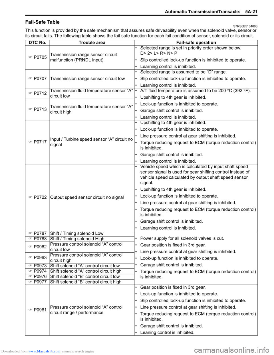
Fail-Safe TableS7RS0B5104008
This function is provided by the safe mechanism that assures safe driveability even when the solenoid valve, sensor or
its circuit fails. The following table shows th e fail-safe function for each fail condition of sensor, solenoid or its circuit.
DTC No. Trouble area Fail-safe operation
) P0705 Transmission range sensor circuit
malfunction (PRNDL input) • Selected range is set in priority order shown below.
D> 2> L> R> N> P
• Slip controlled lock-up function is inhibited to operate.
• Learning control is inhibited.
) P0707 Transmission range sensor circuit low • Selected range is assumed to be “D” range.
• Slip controlled lock-up function is inhibited to operate.
• Learning control is inhibited.
) P0712 Transmission fluid temperature sensor “A”
circuit low • A/T fluid temperature is assumed to be 200
°C (392 °F).
• Upshifting to 4th gear is inhibited.
• Lock-up function is inhibited to operate.
• Garage shift control is inhibited.
• Learning control is inhibited.
)
P0713 Transmission fluid temperature sensor “A”
circuit high
) P0717 Input / Turbine speed sensor “A” circuit no
signal • Upshifting to 4th gear is inhibited.
• Lock-up function is inhibited to operate.
• Line pressure control at gear shifting is inhibited.
• Torque reducing request to ECM (torque reduction control)
is inhibited.
• Garage shift control is inhibited.
• Learning control is inhibited.
) P0722 Output speed sensor circuit no signal • Vehicle speed which is calculated by input shaft speed
sensor signal is used for gear shifting control instead of
vehicle speed calculated by output shaft speed sensor
signal.
• Upshifting to 4th gear is inhibited.
• Lock-up function is inhibited to operate.
• Line pressure control at gear shifting is inhibited.
• Torque reducing request to ECM (torque reduction control) is inhibited.
• Garage shift control is inhibited.
• Learning control is inhibited.
) P0787 Shift / Timing solenoid Low
• Power supply for all solenoid valves is cut.
• Gear position is fixed in 3rd gear.
• Line pressure control at gear shifting is inhibited.
• Look-up function is inhibited to operate.
• Garage shift control is inhibited.
• Torque reducing request to ECM (torque reduction control)
is inhibited.
)
P0788 Shift / Timing solenoid High
) P0962 Pressure control solenoid “A” control
circuit low
) P0963 Pressure control solenoid “A” control
circuit high
) P0973 Shift solenoid “A” control circuit low
) P0974 Shift solenoid “A” control circuit high
) P0976 Shift solenoid “B” control circuit low
) P0977 Shift solenoid “B” control circuit high
) P0961 Pressure control solenoid “A” control
circuit range / performance • Gear position is fixed in 3rd gear.
• Lock-up function is inhibited to operate.
• Slip controlled lock-up function is inhibited to operate.
• Line pressure control at gear shifting is inhibited.
• Torque reducing request to ECM (torque reduction control)
is inhibited.
• Garage shift control is inhibited.
• Leaning control is inhibited.
Page 712 of 1496
Downloaded from www.Manualslib.com manuals search engine 5A-68 Automatic Transmission/Transaxle:
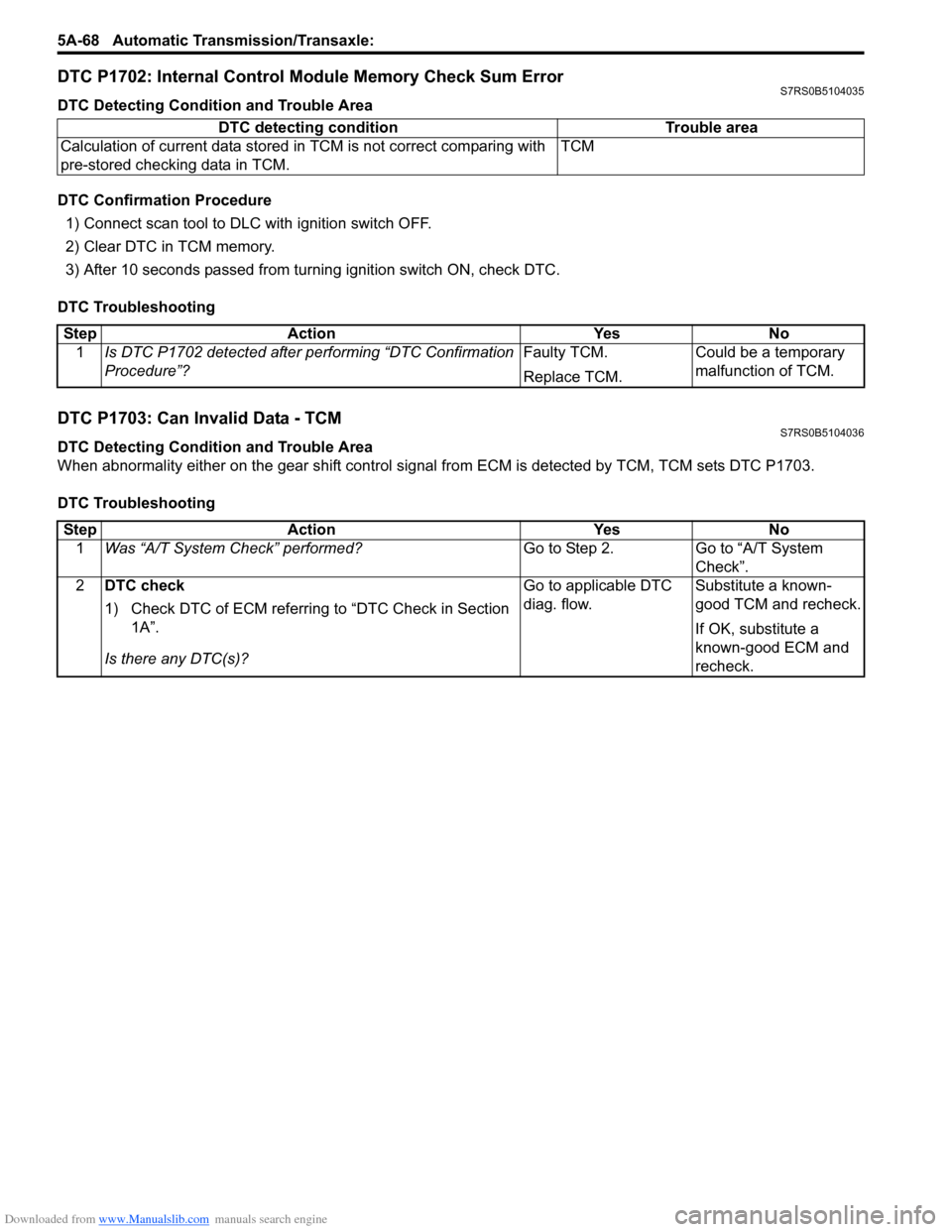
DTC P1702: Internal Control Module Memory Check Sum ErrorS7RS0B5104035
DTC Detecting Condition and Trouble Area
DTC Confirmation Procedure
1) Connect scan tool to DLC with ignition switch OFF.
2) Clear DTC in TCM memory.
3) After 10 seconds passed from turning ignition switch ON, check DTC.
DTC Troubleshooting
DTC P1703: Can Invalid Data - TCMS7RS0B5104036
DTC Detecting Condition and Trouble Area
When abnormality either on the gear shift control signal from ECM is detected by TCM, TCM sets DTC P1703.
DTC Troubleshooting DTC detecting condition Trouble area
Calculation of current data stored in TCM is not correct comparing with
pre-stored checking data in TCM. TCM
Step
Action YesNo
1 Is DTC P1702 detected after performing “DTC Confirmation
Procedure”? Faulty TCM.
Replace TCM.Could be a temporary
malfunction of TCM.
Step
Action YesNo
1 Was “A/T System Check” performed? Go to Step 2.Go to “A/T System
Check”.
2 DTC check
1) Check DTC of ECM referring to “DTC Check in Section
1A”.
Is there any DTC(s)? Go to applicable DTC
diag. flow.
Substitute a known-
good TCM and recheck.
If OK, substitute a
known-good ECM and
recheck.
Page 729 of 1496
Downloaded from www.Manualslib.com manuals search engine Automatic Transmission/Transaxle: 5A-85
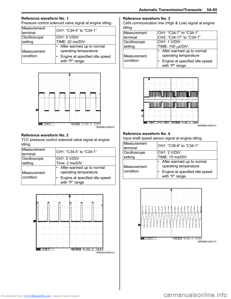
Reference waveform No. 1
Pressure control solenoid valve signal at engine idling.
Reference waveform No. 2
TCC pressure control solenoid valve signal at engine
idling.Reference waveform No. 3
CAN communication line (High & Low) signal at engine
idling.
Reference waveform No. 4
Input shaft speed sensor signal at engine idling.
Measurement
terminal
CH1: “C34-4” to “C34-1”
Oscilloscope
setting CH1: 5 V/DIV
TIME: 20 ms/DIV
Measurement
condition • After warmed up to normal
operating temperature
• Engine at specified idle speed with “P” range.
Measurement
terminal CH1: “C34-5” to “C34-1”
Oscilloscope
setting CH1: 5 V/DIV
Time: 2 ms/DIV
Measurement
condition • After warmed up to normal
operating temperature
• Engine at specified idle speed with “P” range
I3RM0B510029-01
I4RS0A510024-01
Measurement
terminal CH1: “C34-7” to “C34-1”
CH2: “C34-17” to “C34-1”
Oscilloscope
setting CH1: 1 V/DIV
TIME: 100
µs/DIV
Measurement
condition • After warmed up to normal
operating temperature
• Engine at specified idle speed with “P” range.
Measurement
terminal CH1: “C35-6” to “C34-1”
Oscilloscope
setting CH1: 2 V/DIV
TIME: 10 ms/DIV
Measurement
condition • After warmed up to normal
operating temperature
• Engine at specified idle speed with “P” range.
I3RM0B510030-01
I3RM0B510027-01
Page 730 of 1496
Downloaded from www.Manualslib.com manuals search engine 5A-86 Automatic Transmission/Transaxle:
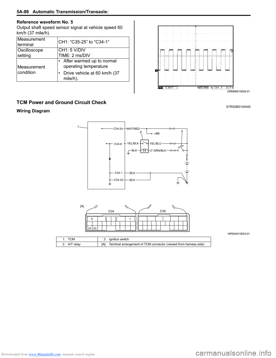
Reference waveform No. 5
Output shaft speed sensor signal at vehicle speed 60
km/h (37 mile/h).
TCM Power and Ground Circuit CheckS7RS0B5104046
Wiring DiagramMeasurement
terminal
CH1: “C35-25” to “C34-1”
Oscilloscope
setting CH1: 5 V/DIV
TIME: 2 ms/DIV
Measurement
condition • After warmed up to normal
operating temperature
• Drive vehicle at 60 km/h (37 mile/h).
I3RM0B510028-01
BLK
BLK
BLK
C34-1
C34-23
C34-6YEL/BLKYEL/BLU
LT GRN/BLK
+BB
C34-24WHT/RED1
23
6
24 23 1
C34C35
[A]
I4RS0A510023-01
1. TCM
3. Ignition switch
2. A/T relay [A]: Terminal arrangement of TCM connector (viewed from harness side)
Page 739 of 1496
Downloaded from www.Manualslib.com manuals search engine Automatic Transmission/Transaxle: 5A-95
5) Shift select lever to “N” position.
NOTE
If select lever is in “P” position, shift select
lever referring to “Select Lever Inspection”.
6) Install cable casing cap (3) to selector bracket (4).
7) Connect cable end (1) to interlock cam (2) with ignition switch turned to ACC position.
8) Drive lock button (5) in cable end until it locks cable expansion and contraction.
9) With select lever set at “P ” position, turn ignition key
to ACC position and then check for the following
conditions.
• With knob button released, ignition key can be turned from ACC position to LOCK position.
• With knob button pressed, ignition key cannot be
turned from ACC position to LOCK position.
10) Install steering column cover. 11) If the vehicle is equipped with air bag system, connect negative cable at battery and enable air bag
system, referring to “Enabling Air Bag System in
Section 8B”.
Transmission Range Sensor (Shift Switch)
Inspection and Adjustment
S7RS0B5106015
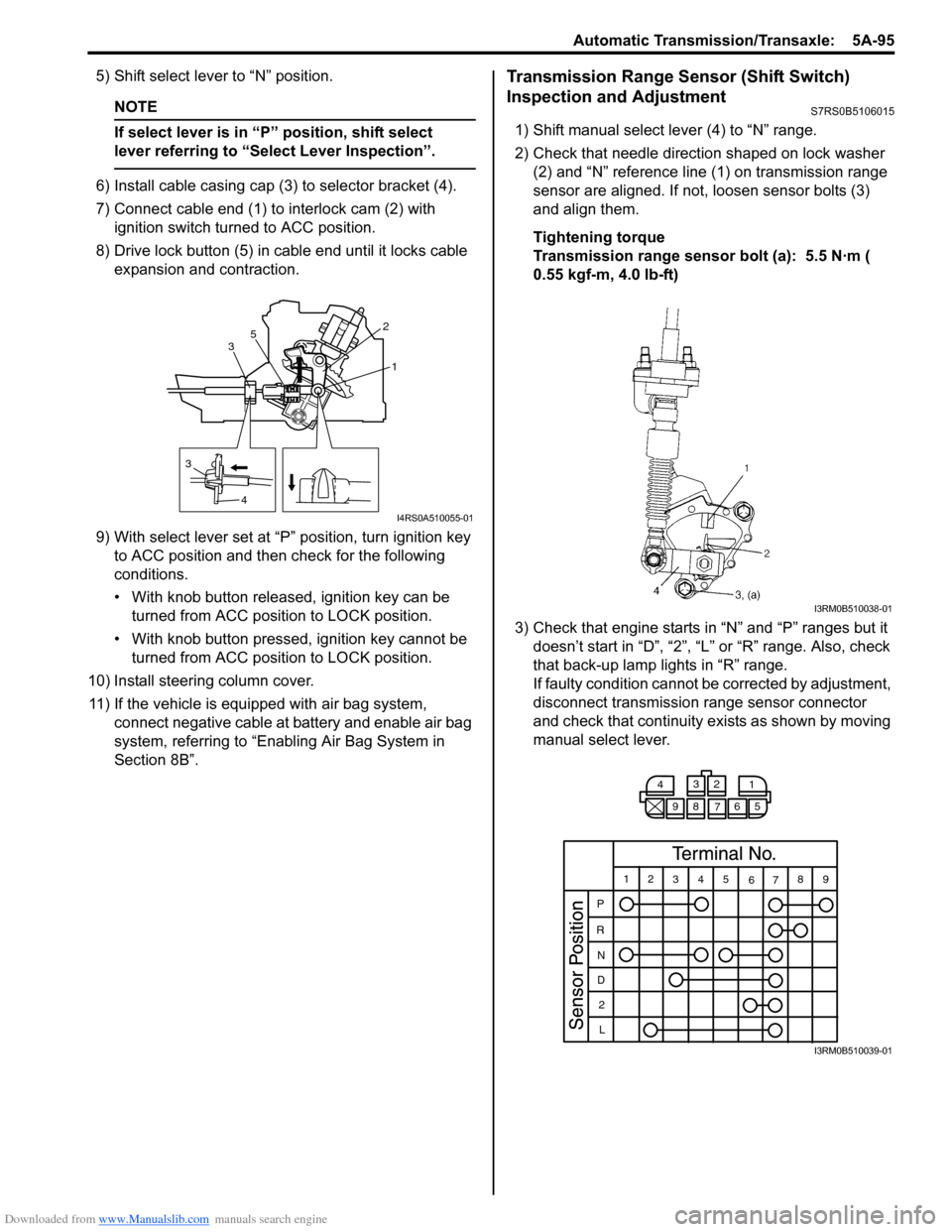
1) Shift manual select lever (4) to “N” range.
2) Check that needle direction shaped on lock washer (2) and “N” reference line (1) on transmission range
sensor are aligned. If not, loosen sensor bolts (3)
and align them.
Tightening torque
Transmission range sensor bolt (a): 5.5 N·m (
0.55 kgf-m, 4.0 lb-ft)
3) Check that engine starts in “N” and “P” ranges but it doesn’t start in “D”, “2”, “L” or “R” range. Also, check
that back-up lamp lights in “R” range.
If faulty condition cannot be corrected by adjustment,
disconnect transmission range sensor connector
and check that continuity ex ists as shown by moving
manual select lever.
3
4 1
2
3 5
I4RS0A510055-01
I3RM0B510038-01
4
3
2
1
98 76 5
12 345
6789
P
R N
D 2
L
I3RM0B510039-01