Contact coil cable SUZUKI SWIFT 2008 2.G Service Workshop Manual
[x] Cancel search | Manufacturer: SUZUKI, Model Year: 2008, Model line: SWIFT, Model: SUZUKI SWIFT 2008 2.GPages: 1496, PDF Size: 34.44 MB
Page 290 of 1496
Downloaded from www.Manualslib.com manuals search engine 1D-5 Engine Mechanical:
11) Connect negative cable at battery.
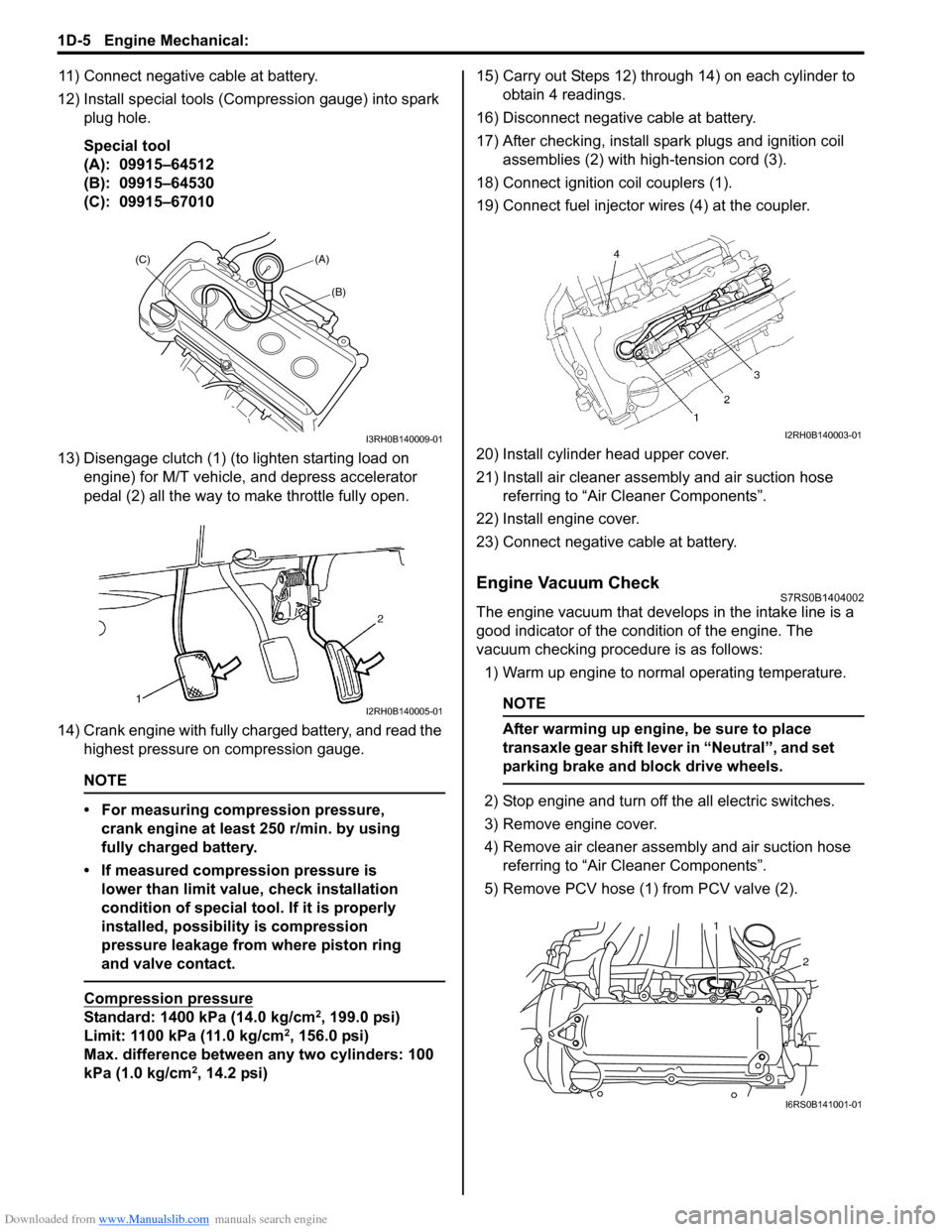
12) Install special tools (Compression gauge) into spark plug hole.
Special tool
(A): 09915–64512
(B): 09915–64530
(C): 09915–67010
13) Disengage clutch (1) (to lighten starting load on engine) for M/T vehicle, and depress accelerator
pedal (2) all the way to make throttle fully open.
14) Crank engine with fully charged battery, and read the highest pressure on compression gauge.
NOTE
• For measuring compression pressure, crank engine at least 250 r/min. by using
fully charged battery.
• If measured compression pressure is lower than limit value, check installation
condition of special tool. If it is properly
installed, possibility is compression
pressure leakage from where piston ring
and valve contact.
Compression pressure
Standard: 1400 kPa (14.0 kg/cm2, 199.0 psi)
Limit: 1100 kPa (11.0 kg/cm2, 156.0 psi)
Max. difference between any two cylinders: 100
kPa (1.0 kg/cm
2, 14.2 psi) 15) Carry out Steps 12) through 14) on each cylinder to
obtain 4 readings.
16) Disconnect negative cable at battery.
17) After checking, install spark plugs and ignition coil assemblies (2) with high-tension cord (3).
18) Connect ignition coil couplers (1).
19) Connect fuel injector wires (4) at the coupler.
20) Install cylinder head upper cover.
21) Install air cleaner assembly and air suction hose referring to “Air Cleaner Components”.
22) Install engine cover.
23) Connect negative cable at battery.
Engine Vacuum CheckS7RS0B1404002
The engine vacuum that develops in the intake line is a
good indicator of the condition of the engine. The
vacuum checking procedure is as follows:
1) Warm up engine to normal operating temperature.
NOTE
After warming up engine, be sure to place
transaxle gear shift lever in “Neutral”, and set
parking brake and block drive wheels.
2) Stop engine and turn off the all electric switches.
3) Remove engine cover.
4) Remove air cleaner assembly and air suction hose referring to “Air Cleaner Components”.
5) Remove PCV hose (1) from PCV valve (2).
(A)
(C)
(B)
I3RH0B140009-01
I2RH0B140005-01
I2RH0B140003-01
2
1
I6RS0B141001-01
Page 402 of 1496
Downloaded from www.Manualslib.com manuals search engine 1I-1 Starting System:
Engine
Starting System
Schematic and Routing Diagram
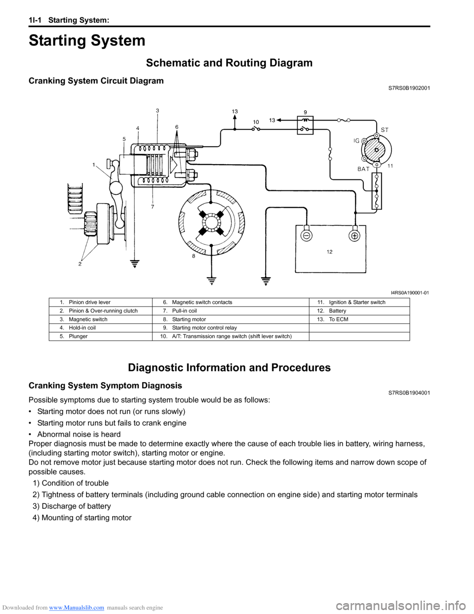
Cranking System Circuit DiagramS7RS0B1902001
Diagnostic Information and Procedures
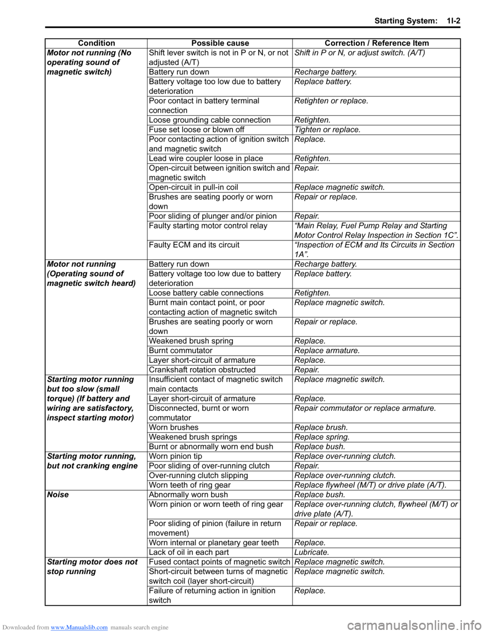
Cranking System Symptom DiagnosisS7RS0B1904001
Possible symptoms due to starting system trouble would be as follows:
• Starting motor does not run (or runs slowly)
• Starting motor runs but fails to crank engine
• Abnormal noise is heard
Proper diagnosis must be made to determine exactly where the cause of each trouble lies in battery, wiring harness,
(including starting motor switch), starting motor or engine.
Do not remove motor just because starting motor does not run. Check the following items and narrow down scope of
possible causes.
1) Condition of trouble
2) Tightness of battery terminals (including ground cable connection on engine side) and starting motor terminals
3) Discharge of battery
4) Mounting of starting motor
I4RS0A190001-01
1. Pinion drive lever 6. Magnetic switch contacts 11. Ignition & Starter switch
2. Pinion & Over-running clutch 7. Pull-in coil 12. Battery
3. Magnetic switch 8. Starting motor 13. To ECM
4. Hold-in coil 9. Starting motor control relay
5. Plunger 10. A/T: Transmission range switch (shift lever switch)
Page 403 of 1496
Downloaded from www.Manualslib.com manuals search engine Starting System: 1I-2
ConditionPossible cause Correction / Reference Item
Motor not running (No
operating sound of
magnetic switch) Shift lever switch is not in P or N, or not
adjusted (A/T)
Shift in P or N, or
adjust switch. (A/T)
Battery run down Recharge battery.
Battery voltage too low due to battery
deterioration Replace battery.
Poor contact in battery terminal
connection Retighten or replace.
Loose grounding cable connection Retighten.
Fuse set loose or blown off Tighten or replace.
Poor contacting action of ignition switch
and magnetic switch Replace.
Lead wire coupler loose in place Retighten.
Open-circuit between ignition switch and
magnetic switch Repair.
Open-circuit in pull-in coil Replace magnetic switch.
Brushes are seating poorly or worn
down Repair or replace.
Poor sliding of plunger and/or pinion Repair.
Faulty starting motor control relay “Main Relay, Fuel Pump Relay and Starting
Motor Control Relay Inspection in Section 1C”.
Faulty ECM and its circuit “Inspection of ECM and Its Circuits in Section
1A”.
Motor not running
(Operating sound of
magnetic switch heard) Battery run down
Recharge battery.
Battery voltage too low due to battery
deterioration Replace battery.
Loose battery cable connections Retighten.
Burnt main contact point, or poor
contacting action of magnetic switch Replace magnetic switch.
Brushes are seating poorly or worn
down Repair or replace.
Weakened brush spring Replace.
Burnt commutator Replace armature.
Layer short-circuit of armature Replace.
Crankshaft rotation obstructed Repair.
Starting motor running
but too slow (small
torque) (If battery and
wiring are satisfactory,
inspect starting motor) Insufficient contact
of magnetic switch
main contacts Replace magnetic switch.
Layer short-circuit of armature Replace.
Disconnected, burnt or worn
commutator Repair commutator or replace armature.
Worn brushes Replace brush.
Weakened brush springs Replace spring.
Burnt or abnormally worn end bush Replace bush.
Starting motor running,
but not cranking engine Worn pinion tip
Replace over-running clutch.
Poor sliding of over-running clutch Repair.
Over-running clutch slipping Replace over-running clutch.
Worn teeth of ring gear Replace flywheel (M/T) or drive plate (A/T).
Noise Abnormally worn bush Replace bush.
Worn pinion or worn teeth of ring gear Replace over-running clutch, flywheel (M/T) or
drive plate (A/T).
Poor sliding of pinion (failure in return
movement) Repair or replace.
Worn internal or planetary gear teeth Replace.
Lack of oil in each part Lubricate.
Starting motor does not
stop running Fused contact points of magnetic switch
Replace magnetic switch.
Short-circuit between turns of magnetic
switch coil (layer short-circuit) Replace magnetic switch.
Failure of returning action in ignition
switch Replace.
Page 414 of 1496
Downloaded from www.Manualslib.com manuals search engine 1J-4 Charging System:
Diagnostic Information and Procedures
Battery InspectionS7RS0B1A04001
Common Causes of Failure
A battery is not designed to last indefinitely; however, with proper care, it will provide many years of service. If the
battery performs satisfactorily during te st but fails to operate properly for no apparent reason, the following are some
factors that may point to the cause of trouble:
• Accessories left on overnight or for an extended period without the generator operating.
• Slow average driving speeds for short periods.
• Electrical load exceeding generator output partic ularly with addition of aftermarket equipment.
• Defects in charging system such as high resistance, s lipping drive belt, loose generator output terminal, faulty
generator or voltage regulator, Refer to “Generator Symptom Diagnosis”.
• Battery abuse, including failure to keep battery cable terminals clean and tight or loose battery hold down.
• Mechanical problems in electrical sys tem such as shorted or pinched wires.
Visual Inspection
Check for obvious damage, such as cracked or broken case or cover, that could permit loss of electrolyte. If obvious
damage is noted, replace battery. Determine cause of damage and correct as needed.
Generator Symptom DiagnosisS7RS0B1A04002
CAUTION!
• Do not mistake polarities of “IG” terminal and “L” terminal.
• Do not create short circuit between “IG” and “L” terminals. Always connect these terminals through a lamp.
• Do not connect any load between “L” and “E” terminals.
• When connecting charger or booster battery to vehicle battery, refer to “Jump Starting in Case of Emergency”.
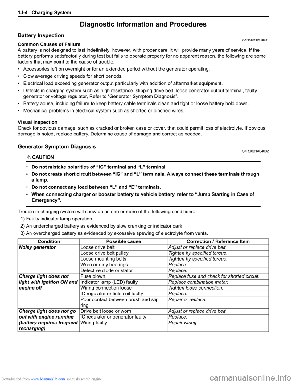
Trouble in charging system will show up as one or more of the following conditions:
1) Faulty indicator lamp operation.
2) An undercharged battery as evidenced by slow cranking or indicator dark.
3) An overcharged battery as evidenced by ex cessive spewing of electrolyte from vents.
Condition Possible cause Correction / Reference Item
Noisy generator Loose drive belt Adjust or replace drive belt.
Loose drive belt pulley Tighten by specified torque.
Loose mounting bolts Tighten by specified torque.
Worn or dirty bearings Replace.
Defective diode or stator Replace.
Charge light does not
light with ignition ON and
engine off Fuse blown
Replace fuse and check for shorted circuit.
Indicator lamp (LED) faulty Replace combination meter.
Wiring connection loose Tighten loose connection.
IC regulator or field coil faulty Replace.
Poor contact between brush and slip
ring Repair or replace.
Charge light does not go
out with engine running
(battery requires frequent
recharging) Drive belt loose or worn
Adjust or replace drive belt.
IC regulator or generator faulty Replace.
Wiring faulty Repair wiring.
Page 416 of 1496
Downloaded from www.Manualslib.com manuals search engine 1J-6 Charging System:
Generator Test (Overcharged Battery Check)S7RS0B1A04004
1) To determine battery condition, refer to “Battery Description”.
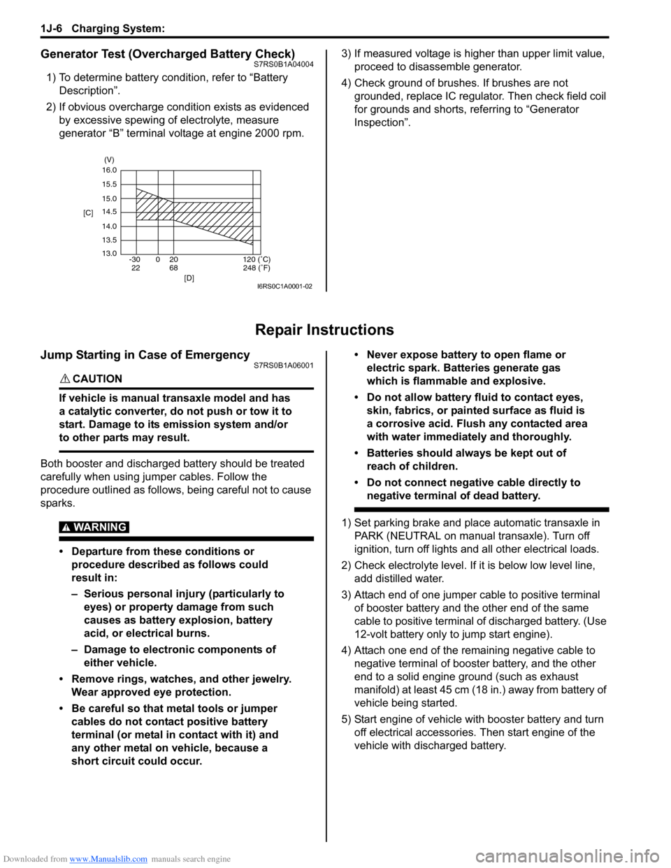
2) If obvious overcharge condition exists as evidenced by excessive spewing of electrolyte, measure
generator “B” terminal voltage at engine 2000 rpm. 3) If measured voltage is higher than upper limit value,
proceed to disassemble generator.
4) Check ground of brushes. If brushes are not grounded, replace IC regulator. Then check field coil
for grounds and shorts, referring to “Generator
Inspection”.
Repair Instructions
Jump Starting in Case of EmergencyS7RS0B1A06001
CAUTION!
If vehicle is manual transaxle model and has
a catalytic converter, do not push or tow it to
start. Damage to its emission system and/or
to other parts may result.
Both booster and discharged battery should be treated
carefully when using ju mper cables. Follow the
procedure outlined as follows, being careful not to cause
sparks.
WARNING!
• Departure from these conditions or procedure described as follows could
result in:
– Serious personal injury (particularly to eyes) or property damage from such
causes as battery explosion, battery
acid, or electrical burns.
– Damage to electronic components of either vehicle.
• Remove rings, watches, and other jewelry. Wear approved eye protection.
• Be careful so that metal tools or jumper cables do not contact positive battery
terminal (or metal in contact with it) and
any other metal on vehicle, because a
short circuit could occur. • Never expose battery to open flame or
electric spark. Batteries generate gas
which is flammable and explosive.
• Do not allow battery fluid to contact eyes, skin, fabrics, or painted surface as fluid is
a corrosive acid. Flush any contacted area
with water immediately and thoroughly.
• Batteries should always be kept out of reach of children.
• Do not connect negative cable directly to negative terminal of dead battery.
1) Set parking brake and place automatic transaxle in PARK (NEUTRAL on manual transaxle). Turn off
ignition, turn off lights and all other electrical loads.
2) Check electrolyte level. If it is below low level line, add distilled water.
3) Attach end of one jumper cable to positive terminal of booster battery and the other end of the same
cable to positive terminal of discharged battery. (Use
12-volt battery only to jump start engine).
4) Attach one end of the remaining negative cable to negative terminal of booster battery, and the other
end to a solid engine ground (such as exhaust
manifold) at least 45 cm (18 in.) away from battery of
vehicle being started.
5) Start engine of vehicle with booster battery and turn off electrical accessories. Then start engine of the
vehicle with discharged battery.
16.0
15.5
15.0
14.5
14.0
13.5
13.0 -30 0 20
[C]
[D]
68
22120 (˚C)
248 (˚F)
(V)
I6RS0C1A0001-02
Page 867 of 1496

Downloaded from www.Manualslib.com manuals search engine Table of Contents 6- i
6
Section 6
CONTENTS
Steering
Precautions ................................................. 6-1
Precautions............................................................. 6-1
Precautions on Steering........................................ 6-1
Steering General Diagnosi s.................... 6A-1
Precautions........................................................... 6A-1
Precautions for Steering Diagnosis ..................... 6A-1
Diagnostic Information and Procedures ............ 6A-2 Steering Symptom Diagnosis .............................. 6A-2
Steering Wheel and Column ................... 6B-1
Precautions........................................................... 6B-1
Service Precautions of Steering Wheel and Column.............................................................. 6B-1
General Description ............................................. 6B-1 Steering Wheel and Column Construction .......... 6B-1
Diagnostic Information and Procedures ............ 6B-2 Checking Steering Column for Accident Damage ............................................................ 6B-2
Repair Instructions .............................................. 6B-3 Steering Wheel and Column Construction .......... 6B-3
Steering Wheel Removal and Installation ........... 6B-4
Contact Coil Cable Assembly Removal and Installation ......................................................... 6B-5
Centering Contact Coil Cable Assembly ............. 6B-6
Contact Coil Cable Assembly Inspection ............ 6B-6
Steering Angle Sensor Removal and Installation ......................................................... 6B-6
Steering Angle Sensor Inspection ....................... 6B-6
Steering Column Removal and Installation ......... 6B-7
Steering Column Inspecti on ................................ 6B-8
Ignition Switch Cylinder Assembly Removal and Installation (Non- Keyless Start Model)...... 6B-9
Steering Lock Assembly (Ignition Switch) Removal and Installation................................... 6B-9
Steering Lower Shaft Removal and Installation ....................................................... 6B-10
Specifications ..................................................... 6B-11
Tightening Torque Specifications ...................... 6B-11
Special Tools and Equipmen t ........................... 6B-11
Special Tool ...................................................... 6B-11
Power Assisted Steering System........... 6C-1
Precautions........................................................... 6C-1 Steering System Note .........................................6C-1
Precautions in Diagnosing Troubles ...................6C-1
General Description .............................................6C-2 P/S System Description ......................................6C-2
EPS Diagnosis General Descr iption ...................6C-3
On-Board Diagnostic System Description ...........6C-3
Schematic and Routing Diagram ........................6C-4 EPS System Wiring Circuit Diagram ...................6C-4
Diagnostic Information and Procedures ............6C-5 EPS System Check .............. ...............................6C-5
“EPS” Warning Light Check . ...............................6C-8
DTC Check..........................................................6C-8
DTC Clearance ...................................................6C-9
DTC Table ...........................................................6C-9
Scan Tool Data .................................................6C-11
Visual Inspection ...............................................6C-12
P/S System Symptom Diagnosis ......................6C-12
Serial Data Link Circuit Check ..........................6C-13
“EPS” Warning Light Do es Not Come ON with
Ignition Switch Turn ed ON before Engine
Starts ...............................................................6C-15
“EPS” Warning Light Remains ON Steady after Engine Starts ..........................................6C-16
DTC C1113: Steering Torque Sensor (Main and Sub) Circuit Correlation ............................6C-17
DTC C1114: Steering Torque Sensor Reference Power Supply Circuit .....................6C-19
DTC C1117: Steering Torque Sensor Failure Signal Circuit Low ...........................................6C-21
DTC C1118: Steering Torque Sensor Failure Signal Circuit High...........................................6C-22
DTC C1119: Steering Torque Sensor Power Supply Circuit ..................................................6C-24
DTC C1121 / C1123 / C1124: VSS Circuit
Failure .............................................................6C-26
DTC C1122: Engine Speed Signal....................6C-28
DTC C1141 / C1142 / C1143 / C1145: P/S Motor Circuit Failure ........................................6C-30
DTC C1153: P/S Control Module Power Supply Circuit Voltage Low .............................6C-32
DTC C1155: P/S Control Module Failure ..........6C-33
P/S Control Module Power Supply and Ground Circuit Check ......................................6C-34
Inspection of P/S Control Module and Its Circuits ............................................................6C-35
Page 874 of 1496
Downloaded from www.Manualslib.com manuals search engine 6B-3 Steering Wheel and Column:
Repair Instructions
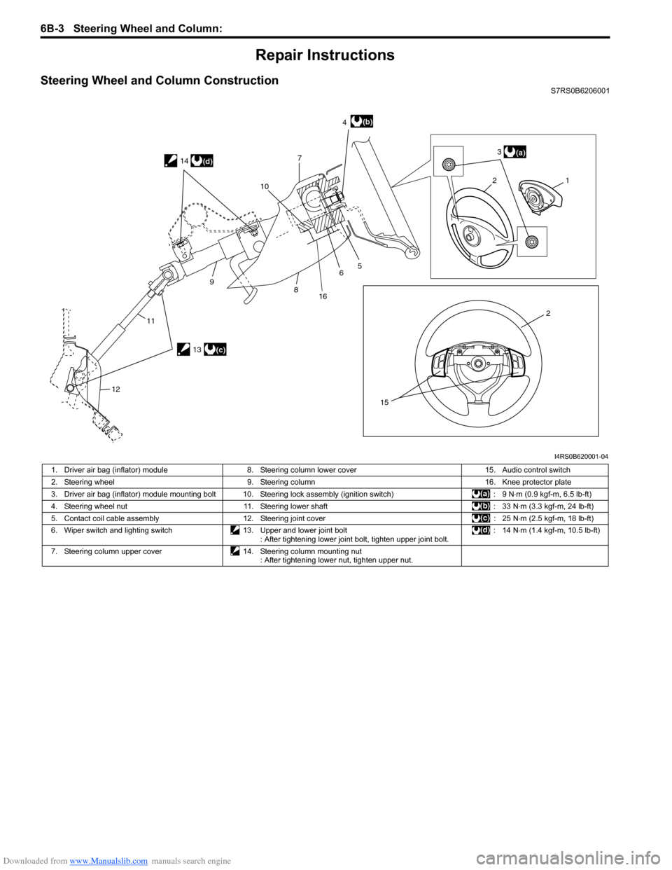
Steering Wheel and Column ConstructionS7RS0B6206001
21
2 3
4
7
5
6
8
9
11
12 10
15
(a)
(b)
13(c)
14
(d)
16
I4RS0B620001-04
1. Driver air bag (inflator) module
8. Steering column lower cover 15. Audio control switch
2. Steering wheel 9. Steering column 16. Knee protector plate
3. Driver air bag (inflator) module mounting bolt 10. Steering lock assembly (ignition switch) : 9 N⋅m (0.9 kgf-m, 6.5 lb-ft)
4. Steering wheel nut 11. Steering lower shaft : 33 N⋅m (3.3 kgf-m, 24 lb-ft)
5. Contact coil cable assembly 12. Steering joint cover : 25 N⋅m (2.5 kgf-m, 18 lb-ft)
6. Wiper switch and lighting switch 13. Upper and lower joint bolt
: After tightening lower joint bolt, tighten upper joint bolt. : 14 N
⋅m (1.4 kgf-m, 10.5 lb-ft)
7. Steering column upper cover 14. Steering column mounting nut
: After tightening lower nut, tighten upper nut.
Page 875 of 1496
Downloaded from www.Manualslib.com manuals search engine Steering Wheel and Column: 6B-4
Steering Wheel Removal and InstallationS7RS0B6206002
CAUTION!
Do not turn the contact coil more than
allowable number of turns (about two and a
half turns from the center position clockwise
or counterclockwise respectively) with
steering wheel removed, or coil will break.
Removal
CAUTION!
Do not hammer the end of the shaft.
Hammering it will loosen the plastic shear
pins which maintain the column length and
impair the collapsible design of the column.
1) Disconnect negative (–) cable at battery.
2) Disable air bag system referring to “Disabling Air
Bag System in Section 8B”.
3) Remove driver air bag (inflator) module from steering wheel. Refer to “Driver Air Bag (Inflator)
Module Removal and Installation in Section 8B”.
4) Disconnect horn connector and audio control switch connector, if equipped.
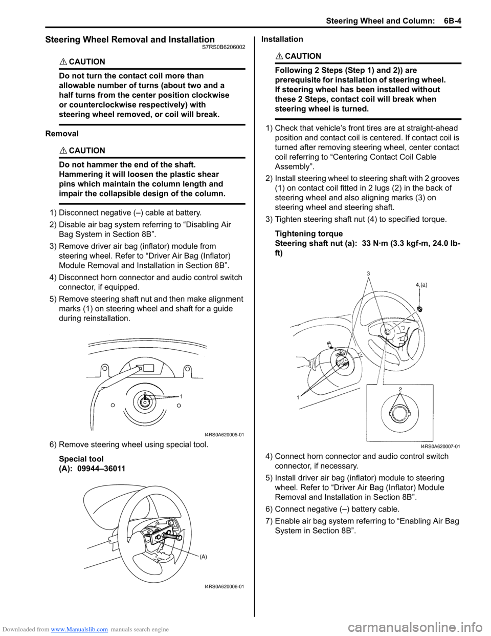
5) Remove steering shaft nut and then make alignment marks (1) on steering wheel and shaft for a guide
during reinstallation.
6) Remove steering wheel using special tool. Special tool
(A): 09944–36011 Installation
CAUTION!
Following 2 Steps (Step 1) and 2)) are
prerequisite for installation of steering wheel.
If steering wheel has
been installed without
these 2 Steps, contact coil will break when
steering wheel is turned.
1) Check that vehicle’s front tires are at straight-ahead position and contact coil is centered. If contact coil is
turned after removing steering wheel, center contact
coil referring to “Centering Contact Coil Cable
Assembly”.
2) Install steering wheel to steering shaft with 2 grooves (1) on contact coil fitted in 2 lugs (2) in the back of
steering wheel and also aligning marks (3) on
steering wheel and steering shaft.
3) Tighten steering shaft nut (4) to specified torque.
Tightening torque
Steering shaft nut (a): 33 N·m (3.3 kgf-m, 24.0 lb-
ft)
4) Connect horn connector and audio control switch connector, if necessary.
5) Install driver air bag (inflator) module to steering wheel. Refer to “Driver Air Bag (Inflator) Module
Removal and Installati on in Section 8B”.
6) Connect negative (–) battery cable.
7) Enable air bag system refe rring to “Enabling Air Bag
System in Section 8B”.
I4RS0A620005-01
(A)
I4RS0A620006-01
I4RS0A620007-01
Page 876 of 1496
Downloaded from www.Manualslib.com manuals search engine 6B-5 Steering Wheel and Column:
Contact Coil Cable Assembly Removal and
Installation
S7RS0B6206003
CAUTION!
Do not turn contact coil more than allowable
number of turns (about two and a half turns
from the center position clockwise or
counterclockwise respectively), or coil will
break.
Removal
1) Disconnect negative (–) cable at battery.
2) Disable air bag system referring to “Disabling Air Bag System in Section 8B”.
3) Remove steering wheel from steering column referring to “Steering Wheel Removal and
Installation”.
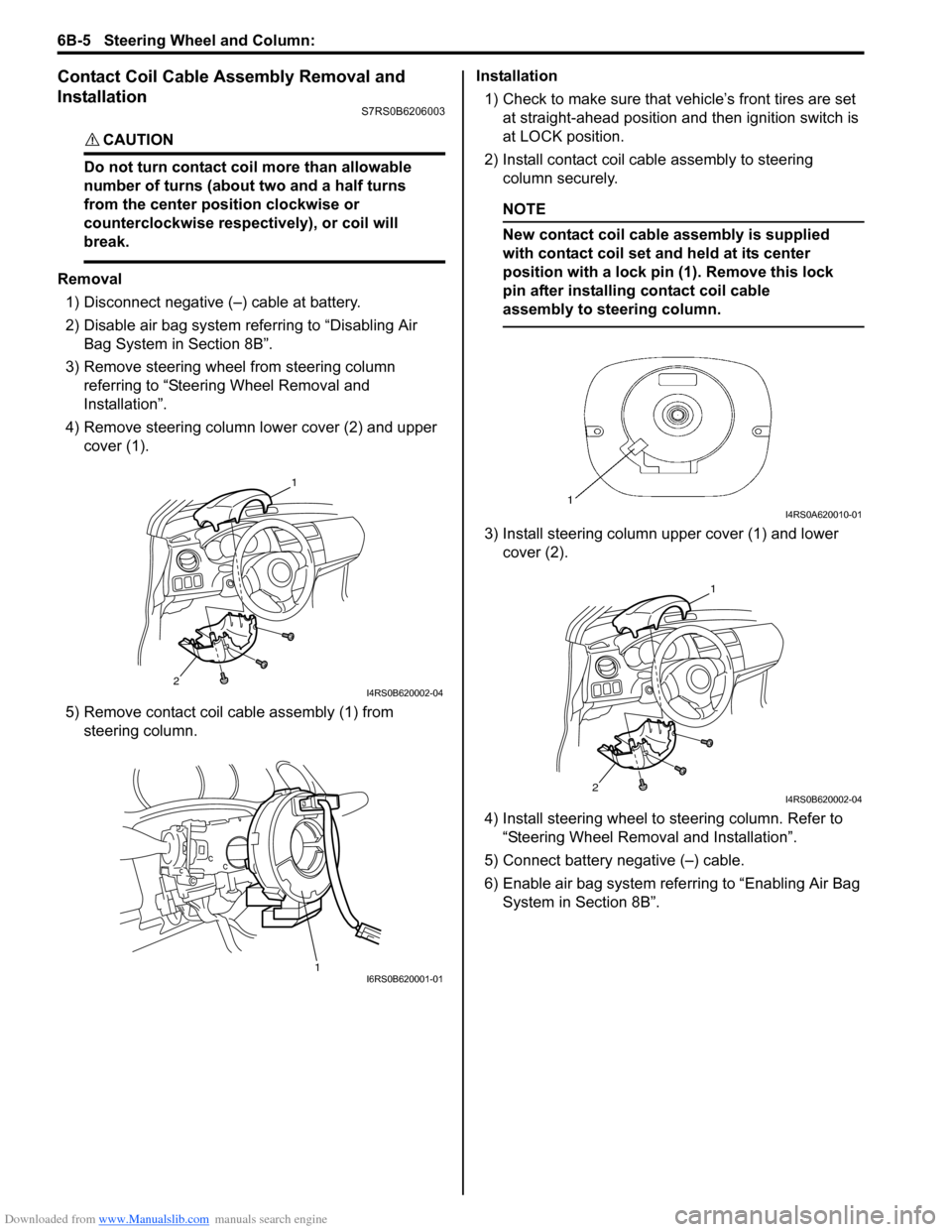
4) Remove steering column lower cover (2) and upper cover (1).
5) Remove contact coil cable assembly (1) from steering column. Installation
1) Check to make sure that vehicle’s front tires are set
at straight-ahead position and then ignition switch is
at LOCK position.
2) Install contact coil cable assembly to steering column securely.
NOTE
New contact coil cable assembly is supplied
with contact coil set and held at its center
position with a lock pin (1). Remove this lock
pin after installing contact coil cable
assembly to steering column.
3) Install steering column upper cover (1) and lower cover (2).
4) Install steering wheel to steering column. Refer to
“Steering Wheel Removal and Installation”.
5) Connect battery negative (–) cable.
6) Enable air bag system refe rring to “Enabling Air Bag
System in Section 8B”.
2
1
I4RS0B620002-04
1I6RS0B620001-01
I4RS0A620010-01
2
1
I4RS0B620002-04
Page 877 of 1496
Downloaded from www.Manualslib.com manuals search engine Steering Wheel and Column: 6B-6
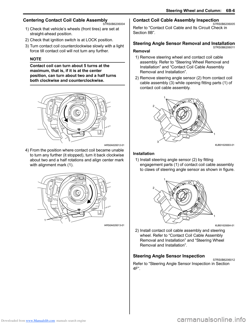
Centering Contact Coil Cable AssemblyS7RS0B6206004
1) Check that vehicle’s wheels (front tires) are set at straight-ahead position.
2) Check that ignition swit ch is at LOCK position.
3) Turn contact coil counterclockwise slowly with a light force till contact coil will not turn any further.
NOTE
Contact coil can turn about 5 turns at the
maximum, that is, if it is at the center
position, can turn about two and a half turns
both clockwise and counterclockwise.
4) From the position where contact coil became unable to turn any further (it stopped), turn it back clockwise
about two and a half rotations and align center mark
with alignment mark (1).
Contact Coil Cable Assembly InspectionS7RS0B6206005
Refer to “Contact Coil Cable and Its Circuit Check in
Section 8B”.
Steering Angle Sensor Removal and InstallationS7RS0B6206011
Removal
1) Remove steering wheel and contact coil cable assembly. Refer to “Ste ering Wheel Removal and
Installation” and “Contact Coil Cable Assembly
Removal and Installation”.
2) Remove steering angle sensor (2) from contact coil cable assembly (3) while op ening fitting parts (1) of
contact coil cable assembly.
Installation 1) Install steering angle sensor (2) by fitting engagement parts (1) of contact coil cable assembly
to claws of steering angle sensor as shown in figure.
2) Install contact coil cable assembly and steering wheel. Refer to “Contact Coil Cable Assembly
Removal and Installation” and “Steering Wheel
Removal and Installation”.
Steering Angle Sensor InspectionS7RS0B6206012
Refer to “Steering Angle Sens or Inspection in Section
4F”.
I4RS0A620012-01
1
I4RS0A620013-01
1
1
2
3I6JB01620003-01
1
1
2
I6JB01620004-01