Lever fuel SUZUKI SWIFT 2008 2.G Service Workshop Manual
[x] Cancel search | Manufacturer: SUZUKI, Model Year: 2008, Model line: SWIFT, Model: SUZUKI SWIFT 2008 2.GPages: 1496, PDF Size: 34.44 MB
Page 21 of 1496
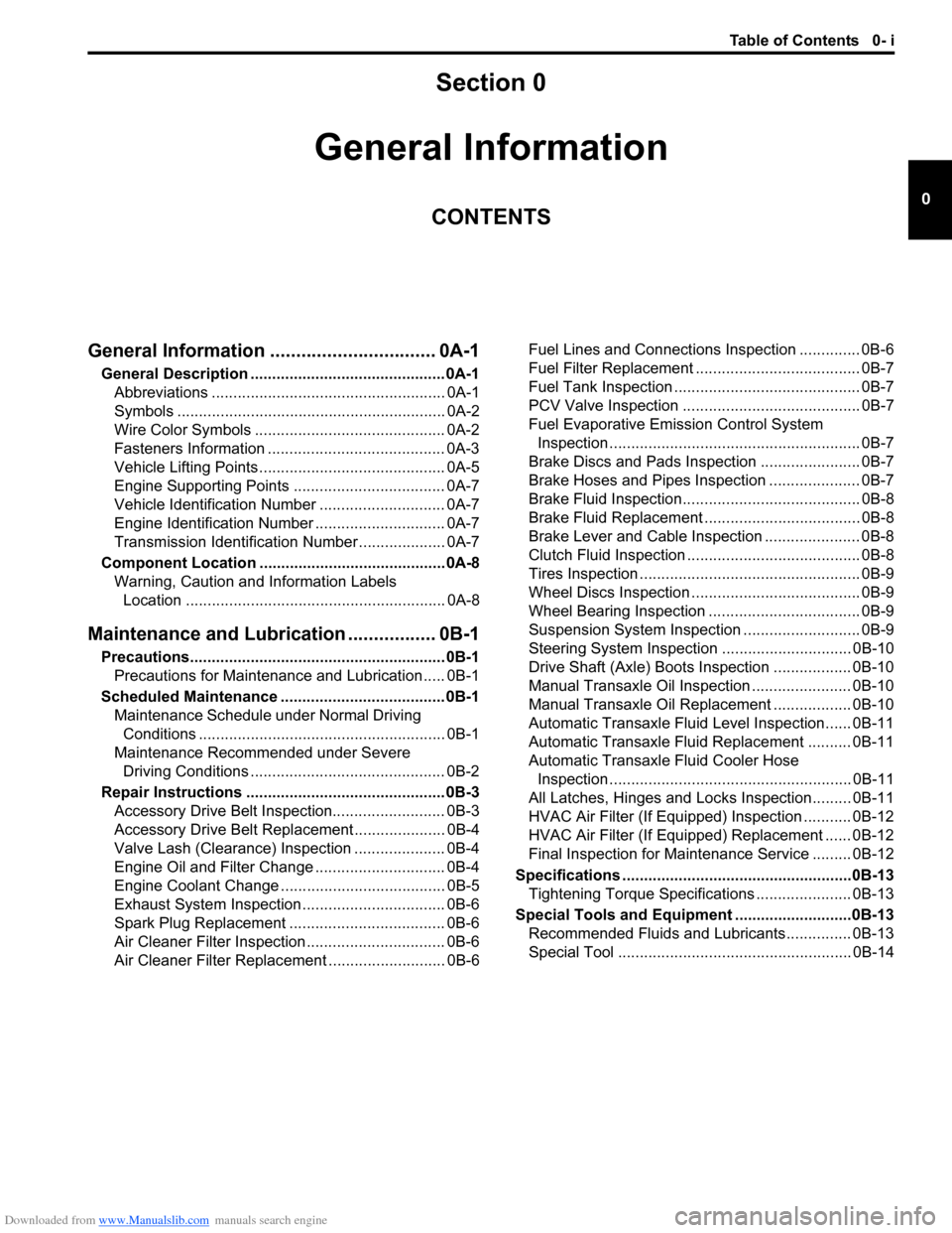
Downloaded from www.Manualslib.com manuals search engine Table of Contents 0- i
0
Section 0
CONTENTS
General Information
General Information ................................ 0A-1
General Description ............................................. 0A-1
Abbreviations ...................................................... 0A-1
Symbols .............................................................. 0A-2
Wire Color Symbols ............................................ 0A-2
Fasteners Information ......................................... 0A-3
Vehicle Lifting Points ........................................... 0A-5
Engine Supporting Points ................................... 0A-7
Vehicle Identification Number ............................. 0A-7
Engine Identification Number .............................. 0A-7
Transmission Identification Number .................... 0A-7
Component Locatio n ........................................... 0A-8
Warning, Caution and Information Labels Location ............................................................ 0A-8
Maintenance and Lubricat ion ................. 0B-1
Precautions........................................................... 0B-1
Precautions for Maintenance and Lubrication ..... 0B-1
Scheduled Maintenance ...................................... 0B-1 Maintenance Schedule under Normal Driving Conditions ......................................................... 0B-1
Maintenance Recommended under Severe Driving Conditions ............................................. 0B-2
Repair Instructions .............................................. 0B-3 Accessory Drive Belt Inspection.......................... 0B-3
Accessory Drive Belt Repl acement ..................... 0B-4
Valve Lash (Clearance) Inspection ..................... 0B-4
Engine Oil and Filter Change .............................. 0B-4
Engine Coolant Change ...... ................................ 0B-5
Exhaust System Inspection ................................. 0B-6
Spark Plug Replacement .................................... 0B-6
Air Cleaner Filter Inspection ................................ 0B-6
Air Cleaner Filter Replac ement ........................... 0B-6 Fuel Lines and Connections Inspection .............. 0B-6
Fuel Filter Replacement ...................................... 0B-7
Fuel Tank Inspection ........................................... 0B-7
PCV Valve Inspection ......................................... 0B-7
Fuel Evaporative Emission Control System
Inspection .......................................................... 0B-7
Brake Discs and Pads Inspection ....................... 0B-7
Brake Hoses and Pipes Inspection ..................... 0B-7
Brake Fluid Inspection......................................... 0B-8
Brake Fluid Replacement .................................... 0B-8
Brake Lever and Cable Inspection ...................... 0B-8
Clutch Fluid Inspection ........................................ 0B-8
Tires Inspection ................................................... 0B-9
Wheel Discs Inspection ....................................... 0B-9
Wheel Bearing Inspection ................................... 0B-9
Suspension System Inspection ........................... 0B-9
Steering System Inspection .............................. 0B-10
Drive Shaft (Axle) Boots Inspection .................. 0B-10
Manual Transaxle Oil Inspection ....................... 0B-10
Manual Transaxle Oil Replacement .................. 0B-10
Automatic Transaxle Fluid Level Inspection...... 0B-11
Automatic Transaxle Fluid Replacement .......... 0B-11
Automatic Transaxle Fluid Cooler Hose Inspection ........................................................ 0B-11
All Latches, Hinges and Locks Inspection......... 0B-11
HVAC Air Filter (If Equipped) Inspection ........... 0B-12
HVAC Air Filter (If Equipped) Replacement ...... 0B-12
Final Inspection for Maint enance Service ......... 0B-12
Specifications .................... .................................0B-13
Tightening Torque Specifications ...................... 0B-13
Special Tools and Equipmen t ...........................0B-13
Recommended Fluids and Lubricants............... 0B-13
Special Tool ...................................................... 0B-14
Page 31 of 1496
Downloaded from www.Manualslib.com manuals search engine Maintenance and Lubrication: 0B-1
General Information
Maintenance and Lubrication
Precautions
Precautions for Maintenance and LubricationS7RS0B0200001
Air Bag Warning
Refer to “Air Bag Warning in Section 00”.
Scheduled Maintenance
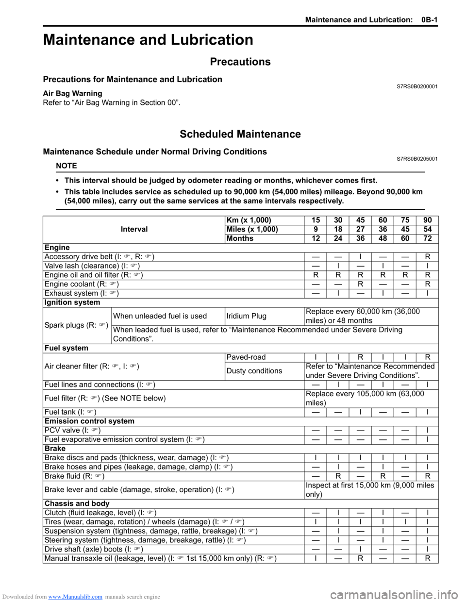
Maintenance Schedule under Normal Driving ConditionsS7RS0B0205001
NOTE
• This interval should be judged by odometer reading or months, whichever comes first.
• This table includes service as scheduled up to 90,000 km (54,000 miles) mileage. Beyond 90,000 km
(54,000 miles), carry out the same services at the same intervals respectively.
Interval Km (x 1,000) 15 30 45 60 75 90
Miles (x 1,000) 9 18 27 36 45 54
Months 12 24 36 48 60 72
Engine
Accessory drive belt (I: ), R: ))——I——R
Valve lash (clearance) (I: )) —I—I—I
Engine oil and oil filter (R: )) RRRRRR
Engine coolant (R: ))— —R— — R
Exhaust system (I: )) —I—I—I
Ignition system
Spark plugs (R: ) )When unleaded fuel is used Iridium Plug
Replace every 60,000 km (36,000
miles) or 48 months
When leaded fuel is used, refer to “Maintenance Recommended under Severe Driving
Conditions”.
Fuel system
Air cleaner filter (R: ), I: )) Paved-road
I I R I I R
Dusty conditions Refer to “Maintenance Recommended
under Severe Driv
ing Conditions”.
Fuel lines and connections (I: )) —I—I—I
Fuel filter (R: )) (See NOTE below) Replace every 105,000 km (63,000
miles)
Fuel tank (I: ))— —I— — I
Emission control system
PCV valve (I: )) ————— I
Fuel evaporative emission control system (I: )) ————— I
Brake
Brake discs and pads (thickness, wear, damage) (I: )) IIIIII
Brake hoses and pipes (leakage, damage, clamp) (I: )) —I—I—I
Brake fluid (R: )) —R—R—R
Brake lever and cable (damage, stroke, operation) (I: )) Inspect at first 15,000 km (9,000 miles
only)
Chassis and body
Clutch (fluid leakage, level) (I: )) —I—I—I
Tires (wear, damage, rotation) / wheels (damage) (I: ) / ) ) IIIIII
Suspension system (tightness, damage, rattle, breakage) (I: )) —I—I—I
Steering system (tightness, damage, breakage, rattle) (I: )) —I—I—I
Drive shaft (axle) boots (I: ))— —I— — I
Manual transaxle oil (leakage, level) (I: ) 1st 15,000 km only) (R: ))I—R——R
Page 43 of 1496
Downloaded from www.Manualslib.com manuals search engine Maintenance and Lubrication: 0B-13
Brake
Foot brake
Check the following:
• that brake pedal has proper travel,
• that brake works properly,
• that it is free from noise,
• that vehicle does not pull to one side when brake is applied.
• and that brake do not drag.
Parking brake
Check that lever has proper travel.
WARNING!
With vehicle parked on a fairly steep slope,
make sure nothing is in the way downhill to
avoid any personal injury or property
damage. Be prepared to apply regular brake
quickly even if vehicle should start to move.
Check to ensure that parking brake is fully effective
when the vehicle is stopped on the safe slope and brake
lever is pulled all the way.
Steering
• Check to ensure that steering wheel is free from instability, or abnormally heavy feeling. • Check that the vehicle does not wander or pull to one
side.
Engine
• Check that engine responds readily at all speeds.
• Check that engine is free from abnormal noise and abnormal vibration.
Body, Wheels and Power Transmitting System
Check that body, wheels and power transmitting system
are free from abnormal noise and abnormal vibration or
any other abnormal condition.
Meters and Gauge
Check that speedometer, odometer, fuel meter,
temperature gauge, etc. are operating accurately.
Lights
Check that all lights operate properly.
Windshield Defroster
Periodically check that ai r comes out from defroster
outlet when operating heater or air conditioning.
Set mode control lever to defroster position and fan
switch lever to “HI” position for this check.
Specifications
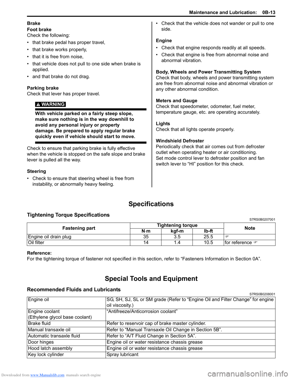
Tightening Torque SpecificationsS7RS0B0207001
Reference:
For the tightening torque of fastener not specified in this section, refer to “Fasteners Information in Section 0A”.
Special Tools and Equipment
Recommended Fluids and LubricantsS7RS0B0208001
Fastening part Tightening torque
Note
N ⋅mkgf-mlb-ft
Engine oil drain plug 35 3.5 25.5 )
Oil filter 14 1.4 10.5 for reference )
Engine oilSG, SH, SJ, SL or SM grade (Refer to “Engine Oil and Filter Change” for engine
oil viscosity.)
Engine coolant
(Ethylene glycol base coolant) “Antifreeze/Antico
rrosion coolant”
Brake fluid Refer to reservoir cap of brake master cylinder.
Manual transaxle oil Refer to “Manual Transaxle Oil Change in Section 5B”.
Automatic transaxle fluid Refer to “A/T Fluid Change in Section 5A”.
Door hinges Engine oil or water resistance chassis grease
Hood latch assembly Engine oil or water resistance chassis grease
Key lock cylinder Spray lubricant
Page 58 of 1496
Downloaded from www.Manualslib.com manuals search engine 1A-8 Engine General Information and Diagnosis:
CAN communication system uses the serial communication in which data is transmitted at a high speed. It uses a
twisted pair of two communication lines for the high-speed da ta transmission. As one of its characteristics, multiple
control modules can communicate simultaneously. In addition, it has a function to detect a communication error
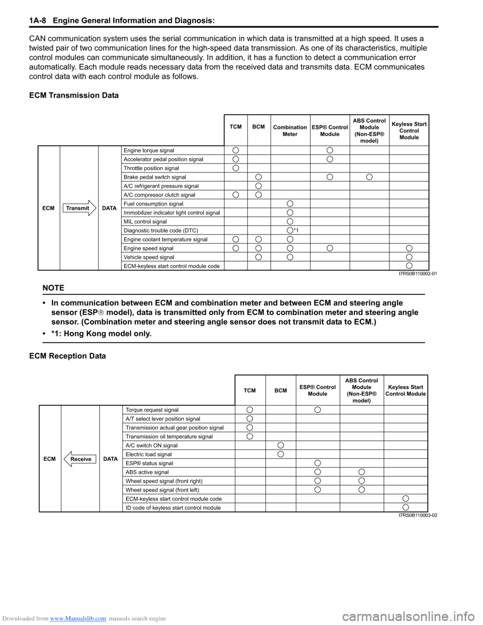
automatically. Each module reads necessary data from the received data and transmits data. ECM communicates
control data with each control module as follows.
ECM Transmission Data
NOTE
• In communication between ECM and combination meter and between ECM and steering angle sensor (ESP ® model), data is transmitted only from ECM to combination meter and steering angle
sensor. (Combination meter and steering angle sensor does not transmit data to ECM.)
• *1: Hong Kong model only.
ECM Reception Data
Engine torque signal
Accelerator pedal position signal
Throttle position signal
Brake pedal switch signal
A/C refrigerant pressure signal
A/C compressor clutch signal
Fuel consumption signal
Immobilizer indicator light control signal
MIL control signal
Diagnostic trouble code (DTC)
Engine coolant temperature signal
Engine speed signal
Vehicle speed signal
ECM-keyless start control module code TCM BCM
Combination
Meter Keyless Start
ControlModule
Transmit DATA
ECM
ESP® Control
Module ABS Control
Module
(Non-ESP® model)
*1
I7RS0B110002-01
TCM BCM Keyless Start
Control Module
DATA
ECM
Torque request signal
A/T select lever position signal
Transmission actual gear position signal
Transmission oil temperature signal
A/C switch ON signal
Electric load signal
ESP® status signal
ABS active signal
Wheel speed signal (front right)
Wheel speed signal (front left)
ECM-keyless start control module code
ID code of keyless start control module
Receive
ABS Control
Module
(Non-ESP® model)
ESP® Control
Module
I7RS0B110003-02
Page 266 of 1496
Downloaded from www.Manualslib.com manuals search engine 1A-216 Engine General Information and Diagnosis:
Repair Instructions
Idle Speed and IAC Throttle Valve Opening
Inspection
S7RS0B1106001
Before idle speed check, make sure of the following.
• Lead wires and hoses of electronic fuel injection and engine and emission control systems are connected
securely.
• Valve lash is checked according to maintenance schedule.
• Ignition timing is within specification.
• All accessories (wipers, heater, lights, A/C, etc.) are out of service.
• Air cleaner has been properly installed and is in good condition.
• No abnormal air drawn in from air intake system.
After all items are confirmed, check idle speed and IAC
duty as follows.
NOTE
Before starting engine, place transmission
gear shift lever in “Neutral” (shift selector
lever to “P” range for A/T vehicle), and set
parking brake and block drive wheels.
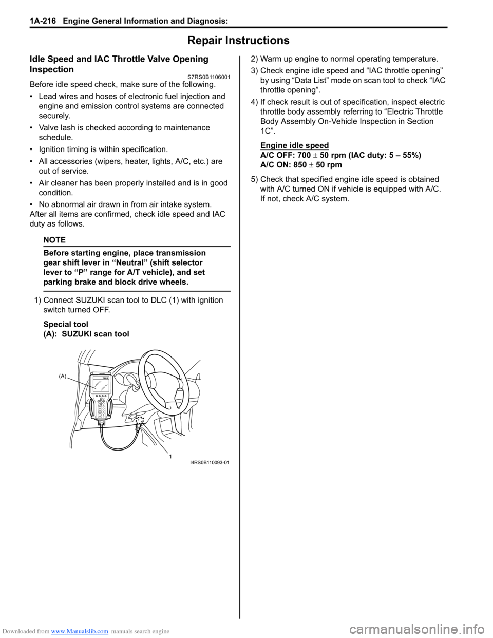
1) Connect SUZUKI scan tool to DLC (1) with ignition
switch turned OFF.
Special tool
(A): SUZUKI scan tool 2) Warm up engine to normal operating temperature.
3) Check engine idle speed and “IAC throttle opening”
by using “Data List” mode on scan tool to check “IAC
throttle opening”.
4) If check result is out of sp ecification, inspect electric
throttle body assembly referring to “Electric Throttle
Body Assembly On-Vehicle Inspection in Section
1C”.
Engine idle speed
A/C OFF: 700 ± 50 rpm (IAC duty: 5 – 55%)
A/C ON: 850 ± 50 rpm
5) Check that specified engine idle speed is obtained with A/C turned ON if vehi cle is equipped with A/C.
If not, check A/C system.
(A)
1
I4RS0B110093-01
Page 289 of 1496
Downloaded from www.Manualslib.com manuals search engine Engine Mechanical: 1D-4
Targeted Timing Varying Operation
Diagnostic Information and Procedures
Compression CheckS7RS0B1404001
Check compression pressure on all 4 cylinders as
follows:
1) Warm up engine to normal operating temperature.
2) Stop engine after warming up.
NOTE
After warming up engine, place transaxle
gear shift lever in “Neutral”, and set parking
brake and block drive wheels.
3) Disconnect negative cable at battery.
4) Remove engine cover.
5) Remove air cleaner assembly and air suction hose referring to “Air Cleaner Components”.
6) Remove cylinder head upper cover.
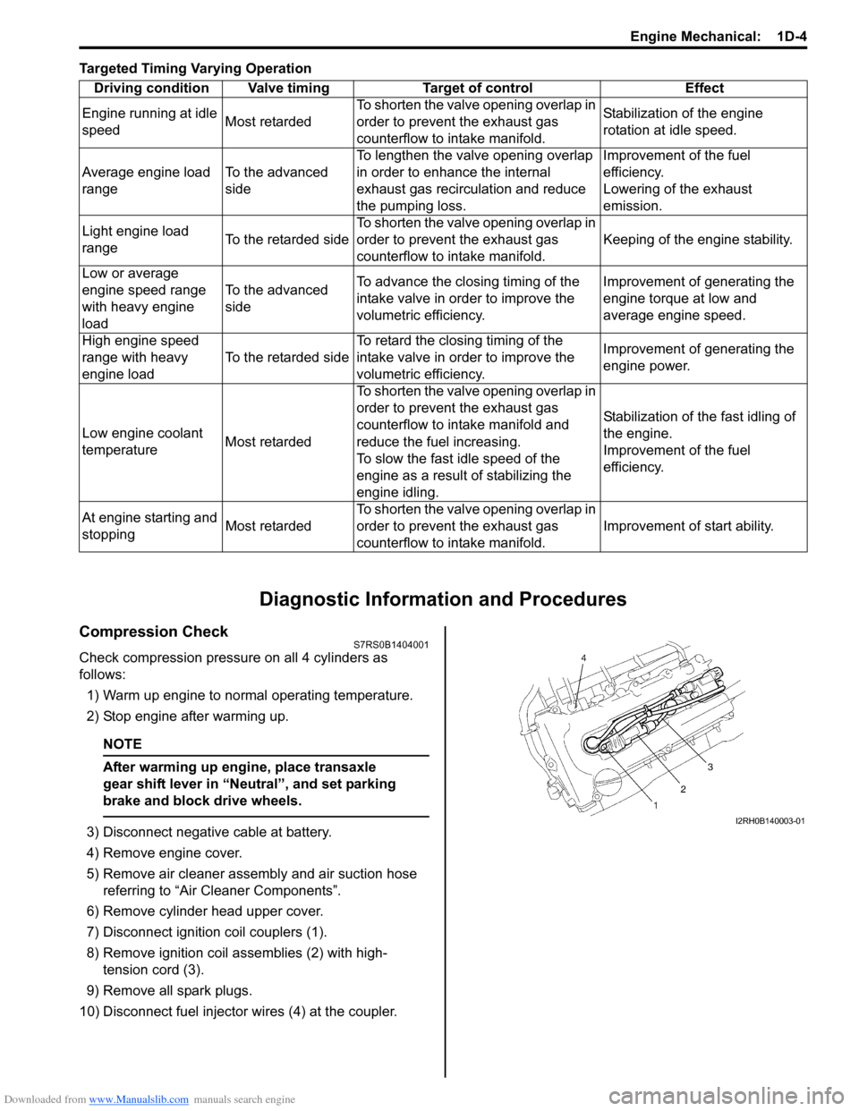
7) Disconnect ignition coil couplers (1).
8) Remove ignition coil assemblies (2) with high- tension cord (3).
9) Remove all spark plugs.
10) Disconnect fuel injector wires (4) at the coupler. Driving condition Valve timing Target of control Effect
Engine running at idle
speed Most retardedTo shorten the valve opening overlap in
order to prevent the exhaust gas
counterflow to in
take manifold. Stabilization of the engine
rotation at idle speed.
Average engine load
range To the advanced
sideTo lengthen the valve opening overlap
in order to enhance the internal
exhaust gas recirculation and reduce
the pumping loss. Improvement of the fuel
efficiency.
Lowering of the exhaust
emission.
Light engine load
range To the retarded sideTo shorten the valve opening overlap in
order to prevent the exhaust gas
counterflow to in
take manifold. Keeping of the engine stability.
Low or average
engine speed range
with heavy engine
load To the advanced
side
To advance the closing timing of the
intake valve in order to improve the
volumetric efficiency. Improvement of generating the
engine torque at low and
average engine speed.
High engine speed
range with heavy
engine load To the retarded sideTo retard the closing timing of the
intake valve in order to improve the
volumetric efficiency. Improvement of generating the
engine power.
Low engine coolant
temperature Most retardedTo shorten the valve opening overlap in
order to prevent the exhaust gas
counterflow to intake manifold and
reduce the fuel increasing.
To slow the fast idle speed of the
engine as a result of stabilizing the
engine idling. Stabilization of the fast idling of
the engine.
Improvement of the fuel
efficiency.
At engine starting and
stopping Most retardedTo shorten the valve opening overlap in
order to prevent the exhaust gas
counterflow to in
take manifold. Improvement of start ability.I2RH0B140003-01
Page 290 of 1496
Downloaded from www.Manualslib.com manuals search engine 1D-5 Engine Mechanical:
11) Connect negative cable at battery.
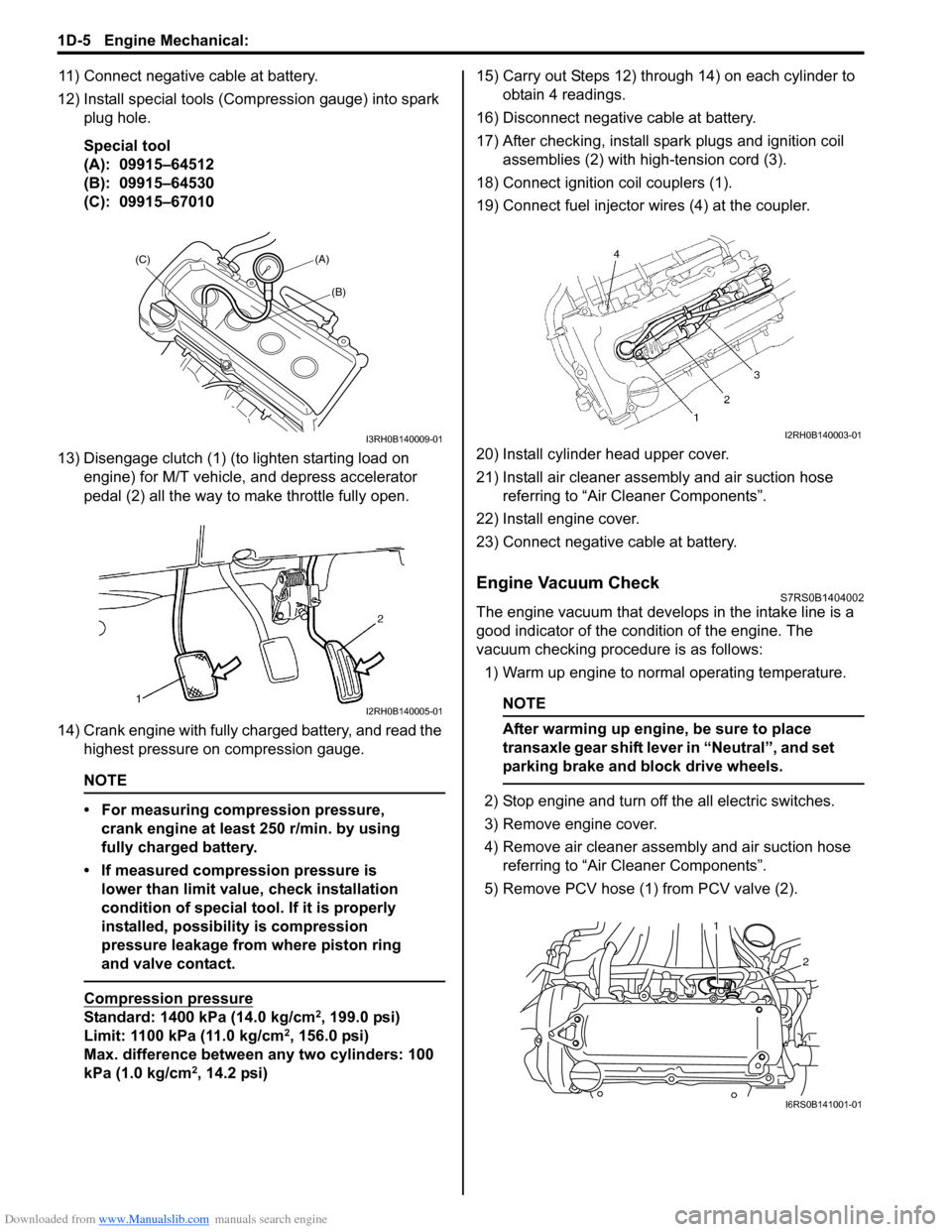
12) Install special tools (Compression gauge) into spark plug hole.
Special tool
(A): 09915–64512
(B): 09915–64530
(C): 09915–67010
13) Disengage clutch (1) (to lighten starting load on engine) for M/T vehicle, and depress accelerator
pedal (2) all the way to make throttle fully open.
14) Crank engine with fully charged battery, and read the highest pressure on compression gauge.
NOTE
• For measuring compression pressure, crank engine at least 250 r/min. by using
fully charged battery.
• If measured compression pressure is lower than limit value, check installation
condition of special tool. If it is properly
installed, possibility is compression
pressure leakage from where piston ring
and valve contact.
Compression pressure
Standard: 1400 kPa (14.0 kg/cm2, 199.0 psi)
Limit: 1100 kPa (11.0 kg/cm2, 156.0 psi)
Max. difference between any two cylinders: 100
kPa (1.0 kg/cm
2, 14.2 psi) 15) Carry out Steps 12) through 14) on each cylinder to
obtain 4 readings.
16) Disconnect negative cable at battery.
17) After checking, install spark plugs and ignition coil assemblies (2) with high-tension cord (3).
18) Connect ignition coil couplers (1).
19) Connect fuel injector wires (4) at the coupler.
20) Install cylinder head upper cover.
21) Install air cleaner assembly and air suction hose referring to “Air Cleaner Components”.
22) Install engine cover.
23) Connect negative cable at battery.
Engine Vacuum CheckS7RS0B1404002
The engine vacuum that develops in the intake line is a
good indicator of the condition of the engine. The
vacuum checking procedure is as follows:
1) Warm up engine to normal operating temperature.
NOTE
After warming up engine, be sure to place
transaxle gear shift lever in “Neutral”, and set
parking brake and block drive wheels.
2) Stop engine and turn off the all electric switches.
3) Remove engine cover.
4) Remove air cleaner assembly and air suction hose referring to “Air Cleaner Components”.
5) Remove PCV hose (1) from PCV valve (2).
(A)
(C)
(B)
I3RH0B140009-01
I2RH0B140005-01
I2RH0B140003-01
2
1
I6RS0B141001-01
Page 378 of 1496
Downloaded from www.Manualslib.com manuals search engine 1G-3 Fuel System:
4) Check that battery voltage is 11 V or more.
5) Measure fuel pressure at each condition.If measured pressure is out of specification, refer to
“Fuel Pressure Check in Section 1A” and check each
possibly defective part. Replace if found defective.
a) Turn ignition switch ON to operate fuel pump and after 2 seconds turn it OFF. Repeat this 3 or 4
times and then check fuel pressure.
Fuel pressure specification
With fuel pump operating and engine
stopped: 270 – 310 kPa (2.7 – 3.1 kg/cm2, 38.4
– 44.0 psi)
b) Start engine and warm it up to normal operating temperature, and measure fuel pressure at
idling.
Fuel pressure specification
At specified idle speed: 270 – 310 kPa (2.7 –
3.1 kg/cm2, 38.4 – 44.0 psi)
c) Stop engine, and measure fuel pressure at one minute after stopping.
Fuel pressure specification
With 1 min. after engine (fuel pump) stop
(Pressure reduces as time passes): Over 300
kPa (3.0 kg/cm
2, 42.7 psi)
6) After checking fuel pressure, remove fuel pressure gauge.
WARNING!
As fuel feed line is still under high fuel
pressure, make sure to release fuel pressure
according to the following procedures.
• Place fuel container under joint.
• Cover joint with rag and loosen joint nut slowly in order to release fuel pressure
gradually.
7) Remove special tools from fuel delivery pipe and fuel feed hose.
8) Connect fuel feed hose to fuel delivery pipe and clamp it securely.
9) With engine OFF and ignition switch ON, check for fuel leaks.
Fuel Cut Operation InspectionS7RS0B1704002
NOTE
Before inspection, make sure that gear shift
lever is in neutral positi on (shift select lever
is “P” range for A/T vehicle), A/C is OFF and
parking brake lever is pulled all the way up.
1) Warm engine up to normal operating temperature.
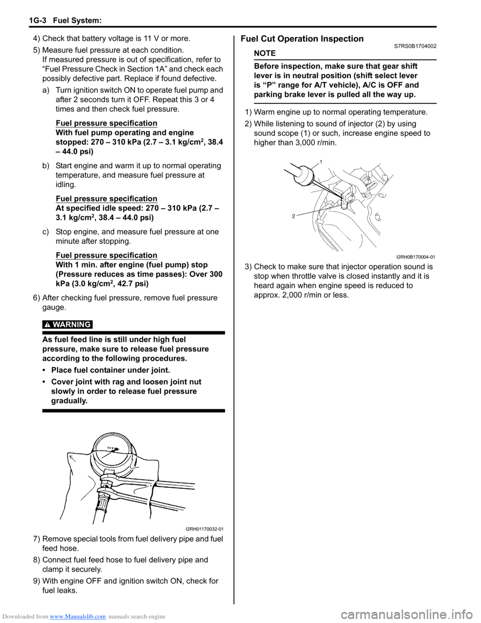
2) While listening to sound of injector (2) by using sound scope (1) or such, increase engine speed to
higher than 3,000 r/min.
3) Check to make sure that injector operation sound is stop when throttle valve is closed instantly and it is
heard again when engine speed is reduced to
approx. 2,000 r/min or less.
I2RH01170032-01
I2RH0B170004-01
Page 382 of 1496
Downloaded from www.Manualslib.com manuals search engine 1G-7 Fuel System:
Fuel Pressure Relief ProcedureS7RS0B1706003
CAUTION!
This work must not be done when engine is
hot. If done so, it may cause adverse effect to
catalyst.
NOTE
If ECM detects DTC(s) after servicing, clear
DTC(s) referring to “DTC Clearance in
Section 1A”.
1) Make sure that engine is cold.
2) Shift transaxle gear shift lever in “Neutral” (shift select lever in “P” range for A/T model), set parking
brake and block drive wheels.
3) Remove relay / fuse box cover.
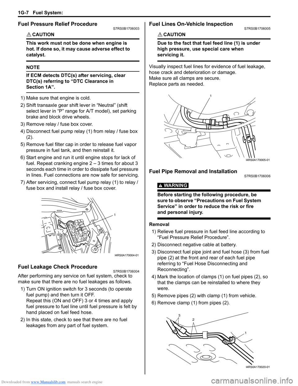
4) Disconnect fuel pump relay (1) from relay / fuse box (2).
5) Remove fuel filter cap in order to release fuel vapor pressure in fuel tank, and then reinstall it.
6) Start engine and run it until engine stops for lack of fuel. Repeat cranking engine 2 – 3 times for about 3
seconds each time in order to dissipate fuel pressure
in lines. Fuel connections are now safe for servicing.
7) After servicing, connect fuel pump relay (1) to relay / fuse box and install re lay / fuse box cover.
Fuel Leakage Check ProcedureS7RS0B1706004
After performing any service on fuel system, check to
make sure that there are no fuel leakages as follows.
1) Turn ON ignition switch for 3 seconds (to operate fuel pump) and then turn it OFF.
Repeat this (ON and OFF) 3 or 4 times and apply
fuel pressure to fuel line until fuel pressure is felt by
hand placed on fuel feed hose.
2) In this state, check to see that there are no fuel leakages from any part of fuel system.
Fuel Lines On-Vehicle InspectionS7RS0B1706005
CAUTION!
Due to the fact that fuel feed line (1) is under
high pressure, use special care when
servicing it.
Visually inspect fuel lines for evidence of fuel leakage,
hose crack and deterioration or damage.
Make sure all cl amps are secure.
Replace parts as needed.
Fuel Pipe Removal and InstallationS7RS0B1706006
WARNING!
Before starting the following procedure, be
sure to observe “Precautions on Fuel System
Service” in order to reduce the risk or fire
and personal injury.
Removal
1) Relieve fuel pressure in fuel feed line according to “Fuel Pressure Relief Procedure”.
2) Disconnect negative cable at battery.
3) Disconnect fuel pipe joint and fuel hose (3) from fuel pipe (2) at the front and rear of each fuel pipe
referring to “Fuel Hose Disconnecting and
Reconnecting”.
4) Mark the location of clamps (1) on fuel pipes (2), so that the clamps can be reinstalled to where they
were.
5) Remove pipes (2) with clamp (1) from vehicle.
6) Remove clamp (1) from pipes (2).
1
I4RS0A170004-01
1
I4RS0A170005-01
2
13
I4RS0A170020-01
Page 403 of 1496
Downloaded from www.Manualslib.com manuals search engine Starting System: 1I-2
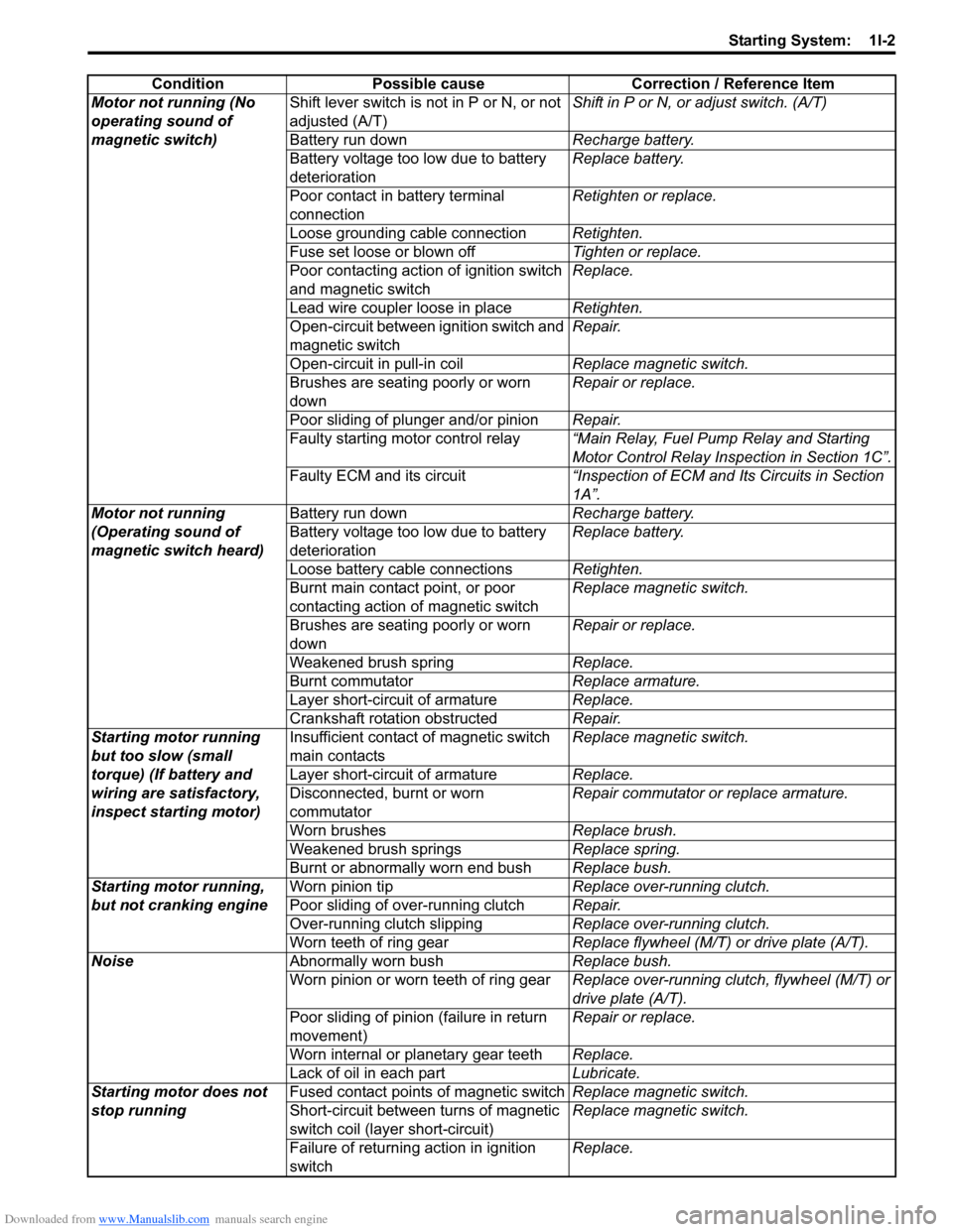
ConditionPossible cause Correction / Reference Item
Motor not running (No
operating sound of
magnetic switch) Shift lever switch is not in P or N, or not
adjusted (A/T)
Shift in P or N, or
adjust switch. (A/T)
Battery run down Recharge battery.
Battery voltage too low due to battery
deterioration Replace battery.
Poor contact in battery terminal
connection Retighten or replace.
Loose grounding cable connection Retighten.
Fuse set loose or blown off Tighten or replace.
Poor contacting action of ignition switch
and magnetic switch Replace.
Lead wire coupler loose in place Retighten.
Open-circuit between ignition switch and
magnetic switch Repair.
Open-circuit in pull-in coil Replace magnetic switch.
Brushes are seating poorly or worn
down Repair or replace.
Poor sliding of plunger and/or pinion Repair.
Faulty starting motor control relay “Main Relay, Fuel Pump Relay and Starting
Motor Control Relay Inspection in Section 1C”.
Faulty ECM and its circuit “Inspection of ECM and Its Circuits in Section
1A”.
Motor not running
(Operating sound of
magnetic switch heard) Battery run down
Recharge battery.
Battery voltage too low due to battery
deterioration Replace battery.
Loose battery cable connections Retighten.
Burnt main contact point, or poor
contacting action of magnetic switch Replace magnetic switch.
Brushes are seating poorly or worn
down Repair or replace.
Weakened brush spring Replace.
Burnt commutator Replace armature.
Layer short-circuit of armature Replace.
Crankshaft rotation obstructed Repair.
Starting motor running
but too slow (small
torque) (If battery and
wiring are satisfactory,
inspect starting motor) Insufficient contact
of magnetic switch
main contacts Replace magnetic switch.
Layer short-circuit of armature Replace.
Disconnected, burnt or worn
commutator Repair commutator or replace armature.
Worn brushes Replace brush.
Weakened brush springs Replace spring.
Burnt or abnormally worn end bush Replace bush.
Starting motor running,
but not cranking engine Worn pinion tip
Replace over-running clutch.
Poor sliding of over-running clutch Repair.
Over-running clutch slipping Replace over-running clutch.
Worn teeth of ring gear Replace flywheel (M/T) or drive plate (A/T).
Noise Abnormally worn bush Replace bush.
Worn pinion or worn teeth of ring gear Replace over-running clutch, flywheel (M/T) or
drive plate (A/T).
Poor sliding of pinion (failure in return
movement) Repair or replace.
Worn internal or planetary gear teeth Replace.
Lack of oil in each part Lubricate.
Starting motor does not
stop running Fused contact points of magnetic switch
Replace magnetic switch.
Short-circuit between turns of magnetic
switch coil (layer short-circuit) Replace magnetic switch.
Failure of returning action in ignition
switch Replace.