Trip SUZUKI SWIFT 2008 2.G Service Workshop Manual
[x] Cancel search | Manufacturer: SUZUKI, Model Year: 2008, Model line: SWIFT, Model: SUZUKI SWIFT 2008 2.GPages: 1496, PDF Size: 34.44 MB
Page 24 of 1496
Downloaded from www.Manualslib.com manuals search engine 0A-3 General Information:
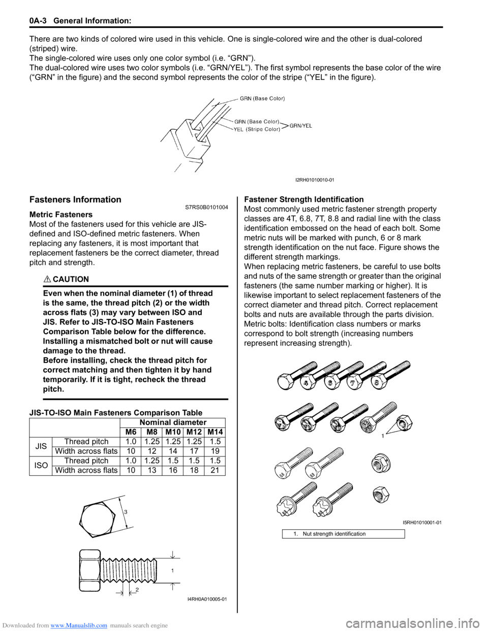
There are two kinds of colored wire used in this vehicle. One is single-colored wire and the other is dual-colored
(striped) wire.
The single-colored wire uses only one color symbol (i.e. “GRN”).
The dual-colored wire uses two color sy mbols (i.e. “GRN/YEL”). The first symbo l represents the base color of the wire
(“GRN” in the figure) and the second symbol represents the color of the stripe (“YEL” in the figure).
Fasteners InformationS7RS0B0101004
Metric Fasteners
Most of the fasteners used for this vehicle are JIS-
defined and ISO-defined metric fasteners. When
replacing any fasteners, it is most important that
replacement fasteners be the correct diameter, thread
pitch and strength.
CAUTION!
Even when the nominal diameter (1) of thread
is the same, the thread pitch (2) or the width
across flats (3) may vary between ISO and
JIS. Refer to JIS-TO-ISO Main Fasteners
Comparison Table below for the difference.
Installing a mismatched bolt or nut will cause
damage to the thread.
Before installing, check the thread pitch for
correct matching and then tighten it by hand
temporarily. If it is tight, recheck the thread
pitch.
JIS-TO-ISO Main Fasteners Comparison Table Fastener Strength Identification
Most commonly used metric fastener strength property
classes are 4T, 6.8, 7T, 8.8 and radial line with the class
identification embossed on the head of each bolt. Some
metric nuts will be marked with punch, 6 or 8 mark
strength identification on the nut face. Figure shows the
different strength markings.
When replacing metric fasteners, be careful to use bolts
and nuts of the same strength or greater than the original
fasteners (the same number marking or higher). It is
likewise important to select replacement fasteners of the
correct diameter and thread
pitch. Correct replacement
bolts and nuts are available through the parts division.
Metric bolts: Identification class numbers or marks
correspond to bolt strength (increasing numbers
represent increasing strength).
I2RH01010010-01
Nominal diameter
M6 M8 M10 M12 M14
JIS Thread pitch 1.0 1.25 1.25 1.25 1.5
Width across flats 10 12 14 17 19
ISO Thread pitch 1.0 1.25 1.5 1.5 1.5
Width across flats 10 13 16 18 21
I4RH0A010005-01
1. Nut strength identification
I5RH01010001-01
Page 32 of 1496
Downloaded from www.Manualslib.com manuals search engine 0B-2 Maintenance and Lubrication:
NOTE
• “R”: Replace or change
• “I”: Inspect and correct, replace or lubricate if necessary
• For spark plugs, replace every 50,000 km if the local law requires.
• Periodic replacement of fuel filter is not necessary if it is not instructed in “Periodic Maintenance Schedule” section of the Owner’s manual. The scheduled maintenance varies depending on the
vehicle specification.
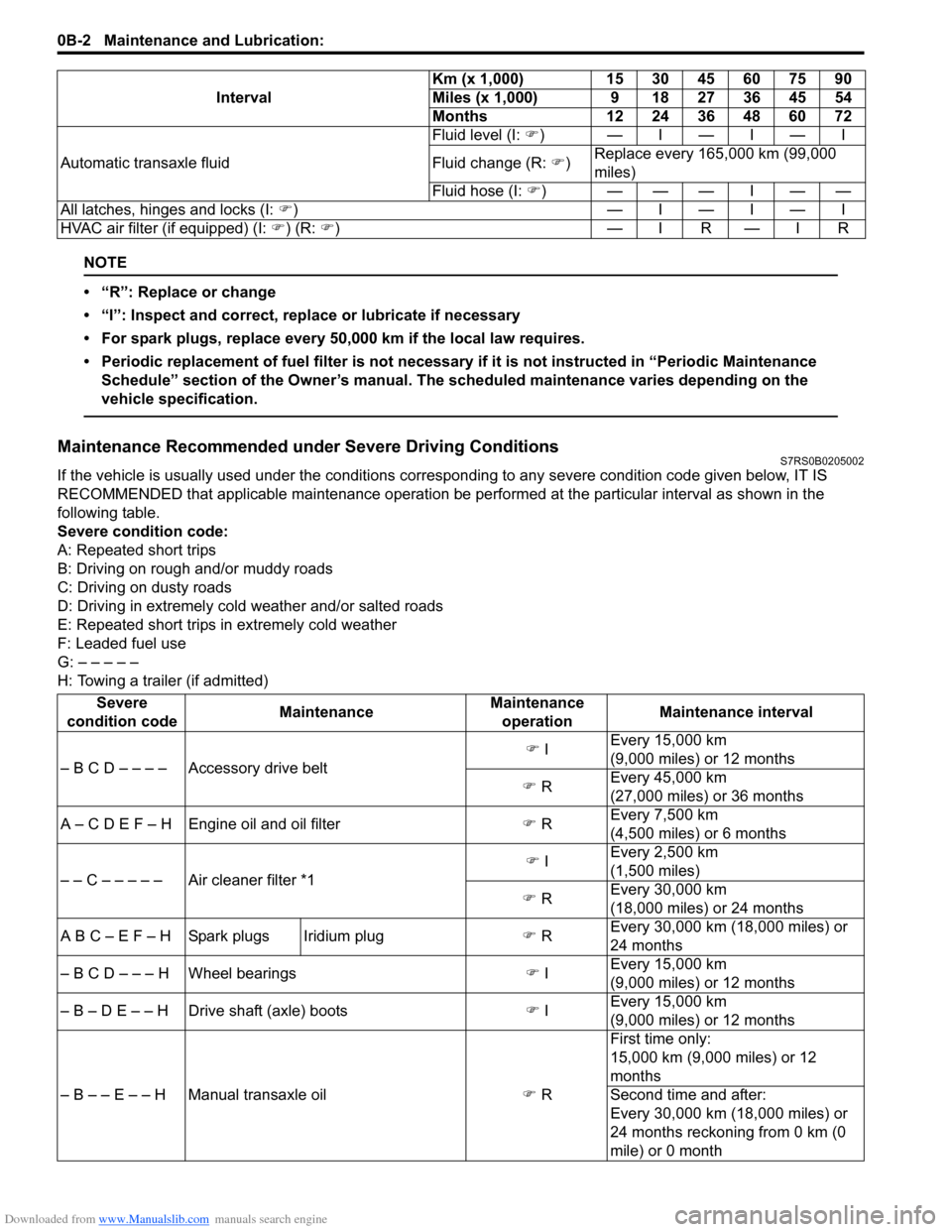
Maintenance Recommended under Severe Driving ConditionsS7RS0B0205002
If the vehicle is usually used under the conditions corres ponding to any severe condition code given below, IT IS
RECOMMENDED that applicable maintenance operation be per formed at the particular interval as shown in the
following table.
Severe condition code:
A: Repeated short trips
B: Driving on rough and/or muddy roads
C: Driving on dusty roads
D: Driving in extremely cold weather and/or salted roads
E: Repeated short trips in extremely cold weather
F: Leaded fuel use
G: – – – – –
H: Towing a trailer (if admitted) Automatic transaxle fluid
Fluid level (I:
�)) —I—I—I
Fluid change (R: �)) Replace every 165,000 km (99,000
miles)
Fluid hose (I: �))———I——
All latches, hinges and locks (I: �)) —I—I—I
HVAC air filter (if equipped) (I: �) ) (R: �))— IR — IR
Interval
Km (x 1,000)
15 30 45 60 75 90
Miles (x 1,000) 9 18 27 36 45 54
Months 12 24 36 48 60 72
Severe
condition code MaintenanceMaintenance
operation Maintenance interval
– B C D – – – – Accessory drive belt �)
I Every 15,000 km
(9,000 miles) or 12 months
�) R Every 45,000 km
(27,000 miles) or 36 months
A – C D E F – H Engine oil and oil filter �) R Every 7,500 km
(4,500 miles) or 6 months
– – C – – – – – Air cleaner filter *1 �)
I Every 2,500 km
(1,500 miles)
�) R Every 30,000 km
(18,000 miles) or 24 months
A B C – E F – H Spark plugs Iridium plug �) R Every 30,000 km (18,000 miles) or
24 months
– B C D – – – H Wheel bearings �) I Every 15,000 km
(9,000 miles) or 12 months
– B – D E – – H Drive shaft (axle) boots �) I Every 15,000 km
(9,000 miles) or 12 months
– B – – E – – H Manual transaxle oil �) R First time only:
15,000 km (9,000 miles) or 12
months
Second time and after:
Every 30,000 km (18,000 miles) or
24 months reckoning from 0 km (0
mile) or 0 month
Page 468 of 1496
Downloaded from www.Manualslib.com manuals search engine 2D-1 Wheels and Tires:
Suspension
Wheels and Tires
Precautions
Precaution for Emergency Flat Tire Repair KitS7RS0B2400001
WARNING!
Flat tire repair sealant including in kit is
harmful. Be sure to observe the following.
Otherwise, your health may be ruined.
• If swallowed, get medical attention immediately.
• Keep out of reach of children.
• Select place where there is good ventilation for this work.
• If it enters eye or contacts skin, wash thoroughly with water. If anything
abnormal still rema ins, get medical
attention immediately.
• Do not discard tire containing sealant as it is. Make sure to remove sealant from tire,
referring to “Tire Repair for Emergency
Repaired-Tire with Sealant”.
• Dispose of sealant as waste oil.
CAUTION!
• When tire repaired with Emergency Flat Tire Repair Kit is brought in, remove flat
tire repair sealant from tire and repair flat
tire referring to “Tire Repair for Emergency
Repaired-Tire with Sealant”.
• Sealant expiration date is printed on bottle label. if it expires, sealant should be
replaced with a new one to ensure
emergency flat tire repair.
General Description
Tires DescriptionS7RS0B2401001
The tire is of tubeless type. The tire is designed to
operate satisfactorily with loads up to the full rated load
capacity when inflated to the recommended inflation
pressures.
Correct tire pressures and driving habits have an
important influence on tire life. Heavy cornering,
excessively rapid acceleration, and unnecessary sharp
braking increase tire wear.
Tire Placard
The “Tire Placard” is located on the left or right door lock
pillar and should be referred to tire information.
The placard lists the maximum load, tire size and cold
tire pressure where applicable.
NOTE
Whether rim size and/or maximum load are
listed or not depends on regulations of each
country.
Inflation of Tires
The pressure recommended for any model is carefully
calculated to give a satisfacto ry ride, stability, steering,
tread wear, tire life and resistance to bruises.
Tire pressure, with tires cold, (after vehicle has set for 3
hours or more, or driven less than one mile) should be
checked monthly or before any extended trip. Set to the
specifications on the “Tire Placard” located on the left
door lock pillar.
It is normal for tire pressure to increase when the tires
become hot during driving.
Do not bleed or reduce tire pressure after driving.
Bleeding reduces the “Cold Inflation Pressure”.
Higher than recommended pressure can cause:
• Hard ride
• Tire bruising or carcass damage
• Rapid tread wear at center of tire
Unequal pressure on same axle can cause:
• Uneven braking
• Steering lead
• Reduced handling
• Swerve on acceleration
Page 479 of 1496
Downloaded from www.Manualslib.com manuals search engine Drive Shaft / Axle: 3A-1
Driveline / Axle
Drive Shaft / Axle
General Description
Front Drive Shaft ConstructionS7RS0B3101001
A constant velocity ball joint is used on the wheel side of both right and left side drive shaft assemblies. For A/T
vehicle, a tripod type constant velocity joint is used on the differential side and center shaft side. For M/T vehicle, a
double offset type constant velocity joint (DOJ) is used on the differential side and center shaft side. The drive shaft
can slide through the tripod joint or the double offset joint (DOJ) in the extension/contraction direction.
Component Location
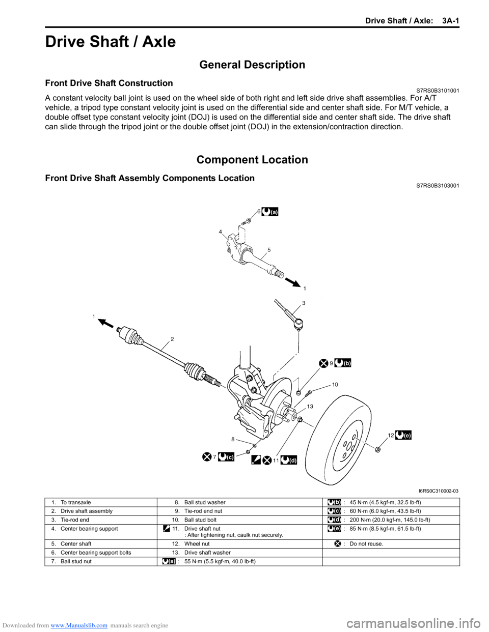
Front Drive Shaft Assembly Components LocationS7RS0B3103001
I6RS0C310002-03
1. To transaxle 8. Ball stud washer : 45 N⋅m (4.5 kgf-m, 32.5 lb-ft)
2. Drive shaft assembly 9. Tie-rod end nut : 60 N⋅m (6.0 kgf-m, 43.5 lb-ft)
3. Tie-rod end 10. Ball stud bolt : 200 N⋅m (20.0 kgf-m, 145.0 lb-ft)
4. Center bearing support 11. Drive shaft nut
: After tightening nut, caulk nut securely. : 85 N
⋅m (8.5 kgf-m, 61.5 lb-ft)
5. Center shaft 12. Wheel nut : Do not reuse.
6. Center bearing support bolts 13. Drive shaft washer
7. Ball stud nut : 55 N⋅m (5.5 kgf-m, 40.0 lb-ft)
Page 482 of 1496
Downloaded from www.Manualslib.com manuals search engine 3A-4 Drive Shaft / Axle:
Front Drive Shaft Assembly On-Vehicle
Inspection
S7RS0B3106002
• Check boots for breakage or deterioration.
• Check wheel side joint for rattle or smooth rotation.
• Check differential side (or center shaft side) joint for smooth rotation.
If any abnormality is found, replace.
Front Drive Shaft Assembly Removal and
Installation
S7RS0B3106003
Removal
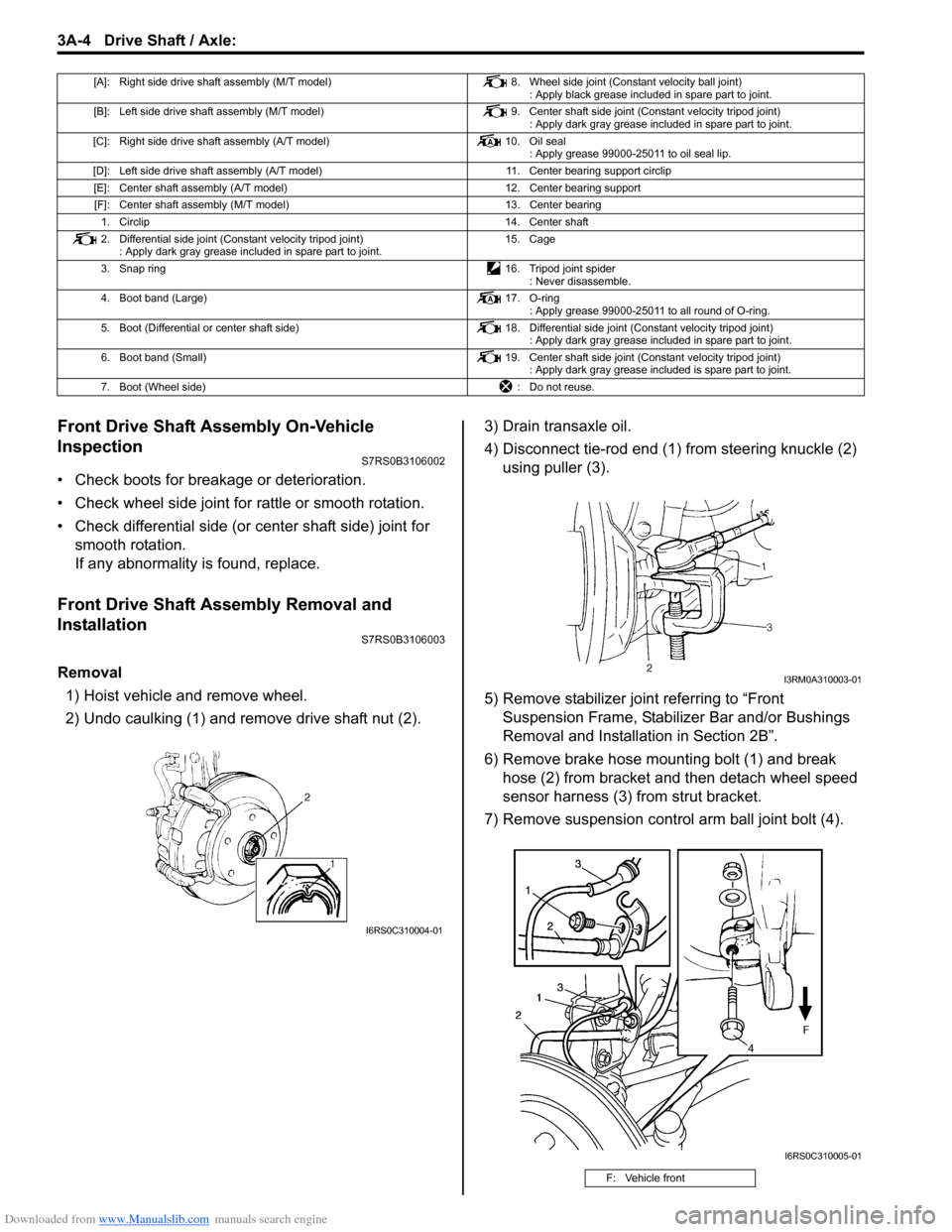
1) Hoist vehicle and remove wheel.
2) Undo caulking (1) and remove drive shaft nut (2). 3) Drain transaxle oil.
4) Disconnect tie-rod end (1) from steering knuckle (2)
using puller (3).
5) Remove stabilizer join t referring to “Front
Suspension Frame, Stabiliz er Bar and/or Bushings
Removal and Installati on in Section 2B”.
6) Remove brake hose mounting bolt (1) and break hose (2) from bracket and then detach wheel speed
sensor harness (3) from strut bracket.
7) Remove suspension contro l arm ball joint bolt (4).
[A]: Right side drive shaft assembly (M/T model) 8. Wheel side joint (Constant velocity ball joint)
: Apply black grease included in spare part to joint.
[B]: Left side drive shaft assembly (M/T model) 9. Center shaft side joint (Constant velocity tripod joint)
: Apply dark gray grease included in spare part to joint.
[C]: Right side drive shaft assembly (A/T model) 10. Oil seal
: Apply grease 99000-25011 to oil seal lip.
[D]: Left side drive shaft assembly (A/T model) 11. Center bearing support circlip
[E]: Center shaft assembly (A/T model) 12. Center bearing support
[F]: Center shaft assembly (M/T model) 13. Center bearing
1. Circlip 14. Center shaft
2. Differential side joint (Constant velocity tripod joint) : Apply dark gray grease included in spare part to joint. 15. Cage
3. Snap ring 16. Tripod joint spider
: Never disassemble.
4. Boot band (Large) 17. O-ring
: Apply grease 99000-25011 to all round of O-ring.
5. Boot (Differential or center shaft side) 18. Differential side joint (Constant velocity tripod joint)
: Apply dark gray grease included in spare part to joint.
6. Boot band (Small) 19. Center shaft side joint (Constant velocity tripod joint)
: Apply dark gray grease included is spare part to joint.
7. Boot (Wheel side) : Do not reuse.
I6RS0C310004-01
F: Vehicle front
I3RM0A310003-01
I6RS0C310005-01
Page 484 of 1496
Downloaded from www.Manualslib.com manuals search engine 3A-6 Drive Shaft / Axle:
Front Drive Shaft Disassembly and ReassemblyS7RS0B3106004
Disassembly
Tripod joint
CAUTION!
• Disassembly of wheel side joint is not allowed. If any noise or damage exists in it,
replace it as assembly.
• Do not disassemble tripod joint spider. If any malcondition is found in it, replace it
as differential side joint assembly.
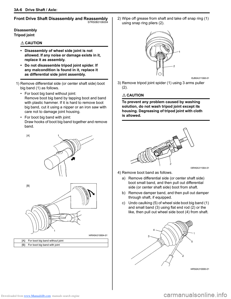
1) Remove differential side (or center shaft side) boot
big band (1) as follows.
• For boot big band without joint:Remove boot big band by tapping boot and band
with plastic hammer. If it is hard to remove boot
big band, cut it using a nipper or an iron saw with
care not to damage joint housing.
• For boot big band with joint: Draw hooks of boot big band together and remove
band. 2) Wipe off grease from shaft and take off snap ring (1)
using snap ring pliers (2).
3) Remove tripod joint spid er (1) using 3 arms puller
(2).
CAUTION!
To prevent any problem caused by washing
solution, do not wash tripod joint except its
housing. Degreasing of tr ipod joint with cloth
is allowed.
4) Remove boot band as follows.
a) Remove differential side (or center shaft side) boot small band, and then pull out differential
side (or center shaft side) boot from shaft.
b) Remove damper band, and then pull out damper through shaft, if equipped.
c) Undo caulking (5) of wheel side boot big band (1) and small band (3) using flat end rod (2) or the
like, then pull out wheel side boot (4) from shaft.
[A]: For boot big band without joint
[B]: For boot big band with joint
I4RH0A310004-01
I5JB0A311008-01
I3RH0A311004-01
I4RS0A310006-01
Page 486 of 1496
Downloaded from www.Manualslib.com manuals search engine 3A-8 Drive Shaft / Axle:
Reassembly
Tripod joint
Judging from abnormality noted before disassembly and
what is found through visual check of component parts
after disassembly, prepare replacing parts and proceed
to reassembly.
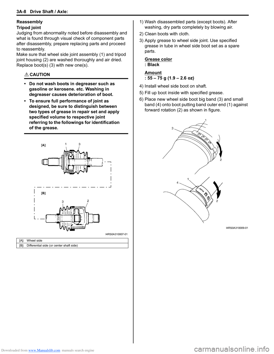
Make sure that wheel side joint assembly (1) and tripod
joint housing (2) are washed thoroughly and air dried.
Replace boot(s) (3) with new one(s).
CAUTION!
• Do not wash boots in degreaser such as gasoline or kerosene. etc. Washing in
degreaser causes deterioration of boot.
• To ensure full performance of joint as designed, be sure to distinguish between
two types of grease in repair set and apply
specified volume to respective joint
referring to the followings for identification
of the grease.
1) Wash disassembled parts (except boots). After washing, dry parts comp letely by blowing air.
2) Clean boots with cloth.
3) Apply grease to wheel side joint. Use specified grease in tube in wheel side boot set as a spare
parts.
Grease color
: Black
Amount
: 55 – 75 g (1.9 – 2.6 oz)
4) Install wheel side boot on shaft.
5) Fill up boot inside with specified grease.
6) Place new wheel side boot big band (3) and small band (4) onto boot putting band outer end (1) against
forward rotation (2) as shown in figure.
[A]: Wheel side
[B]: Differential side (or center shaft side)
I4RS0A310007-01
I4RS0A310009-01
Page 487 of 1496
Downloaded from www.Manualslib.com manuals search engine Drive Shaft / Axle: 3A-9
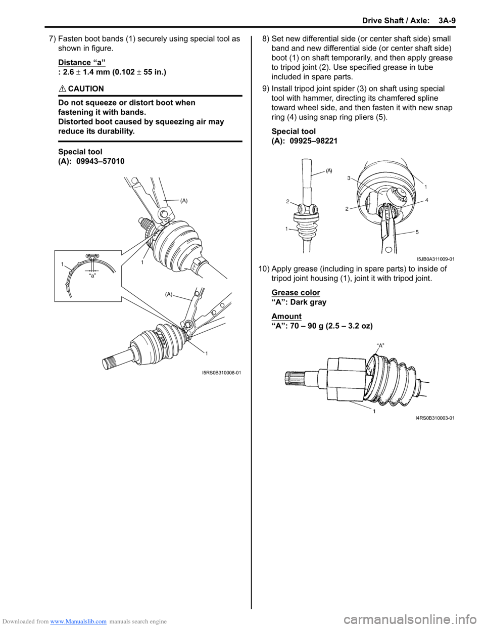
7) Fasten boot bands (1) securely using special tool as
shown in figure.
Distance “a”
: 2.6 ± 1.4 mm (0.102 ± 55 in.)
CAUTION!
Do not squeeze or distort boot when
fastening it with bands.
Distorted boot caused by squeezing air may
reduce its durability.
Special tool
(A): 09943–57010 8) Set new differential side (or center shaft side) small
band and new differential side (or center shaft side)
boot (1) on shaft temporarily, and then apply grease
to tripod joint (2). Use specified grease in tube
included in spare parts.
9) Install tripod joint spider (3) on shaft using special
tool with hammer, directing its chamfered spline
toward wheel side, and then fasten it with new snap
ring (4) using snap ring pliers (5).
Special tool
(A): 09925–98221
10) Apply grease (including in spare parts) to inside of tripod joint housing (1), jo int it with tripod joint.
Grease color
“A”: Dark gray
Amount
“A”: 70 – 90 g (2.5 – 3.2 oz)
(A)
1
(A)
1
“a”
1
I5RS0B310008-01
I5JB0A311009-01
I4RS0B310003-01
Page 1155 of 1496
Downloaded from www.Manualslib.com manuals search engine Air Bag System: 8B-117
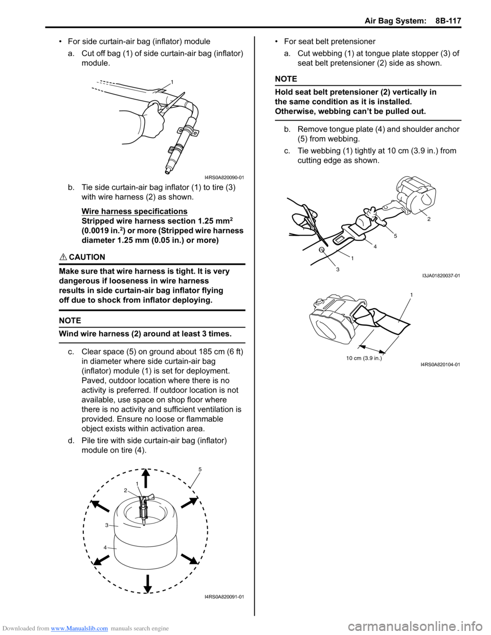
• For side curtain-air bag (inflator) modulea. Cut off bag (1) of side curtain-air bag (inflator) module.
b. Tie side curtain-air bag inflator (1) to tire (3) with wire harness (2) as shown.
Wire harness specifications
Stripped wire harness section 1.25 mm2
(0.0019 in.2) or more (Stripped wire harness
diameter 1.25 mm (0.05 in.) or more)
CAUTION!
Make sure that wire harness is tight. It is very
dangerous if looseness in wire harness
results in side curtain-air bag inflator flying
off due to shock from inflator deploying.
NOTE
Wind wire harness (2) around at least 3 times.
c. Clear space (5) on ground about 185 cm (6 ft) in diameter where side curtain-air bag
(inflator) module (1) is set for deployment.
Paved, outdoor location where there is no
activity is preferred. If outdoor location is not
available, use space on shop floor where
there is no activity and sufficient ventilation is
provided. Ensure no loose or flammable
object exists within activation area.
d. Pile tire with side curtain-air bag (inflator) module on tire (4). • For seat belt pretensioner
a. Cut webbing (1) at tongue plate stopper (3) of seat belt pretensioner (2) side as shown.
NOTE
Hold seat belt pretensioner (2) vertically in
the same condition as it is installed.
Otherwise, webbing can’t be pulled out.
b. Remove tongue plate (4) and shoulder anchor (5) from webbing.
c. Tie webbing (1) tightly at 10 cm (3.9 in.) from
cutting edge as shown.
1
I4RS0A820090-01
1
2
3
4
5
I4RS0A820091-01
3 1 4
5 2I3JA01820037-01
10 cm (3.9 in.)
1
I4RS0A820104-01
Page 1156 of 1496
Downloaded from www.Manualslib.com manuals search engine 8B-118 Air Bag System:
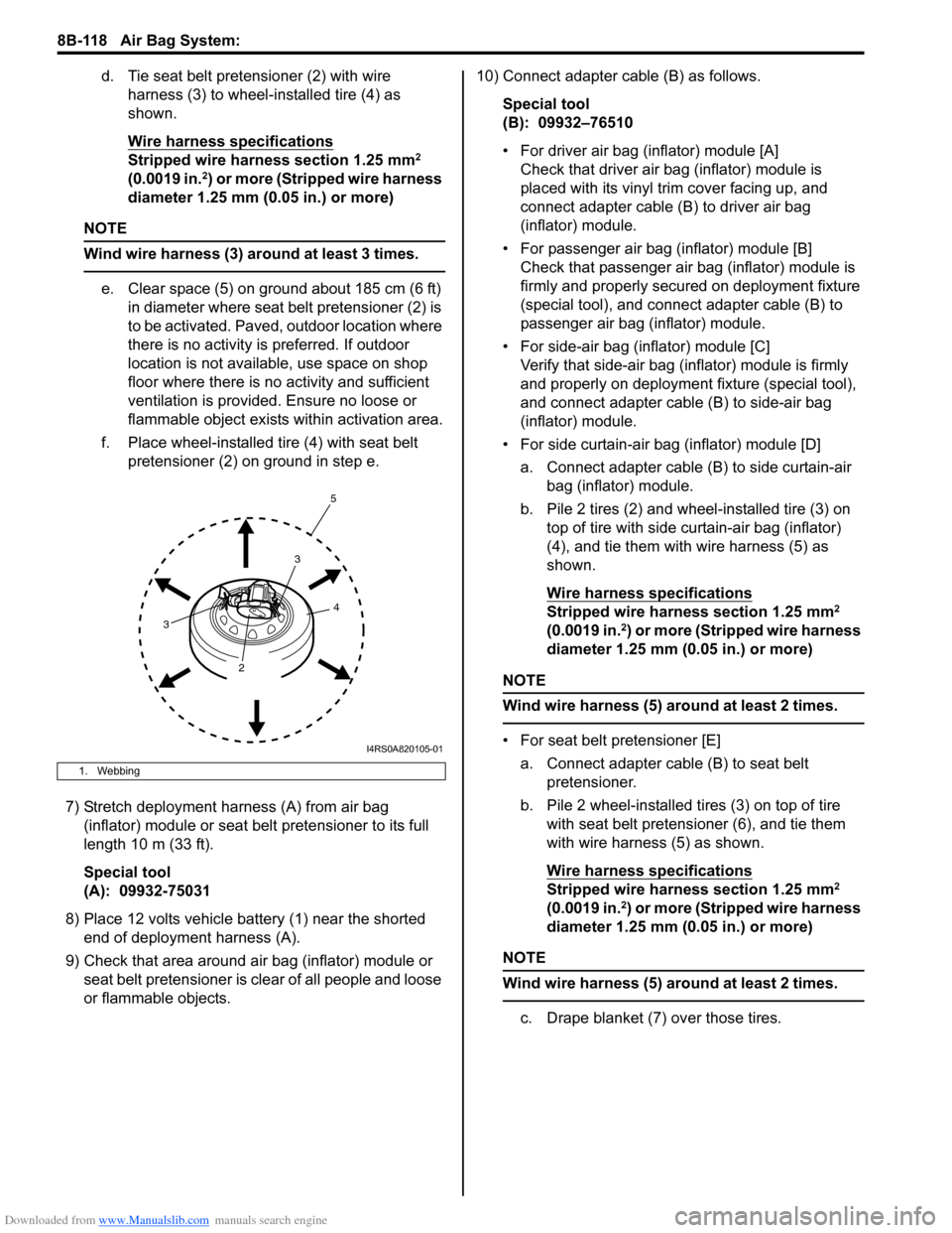
d. Tie seat belt pretensioner (2) with wire harness (3) to wheel-installed tire (4) as
shown.
Wire harness specifications
Stripped wire harness section 1.25 mm2
(0.0019 in.2) or more (Stripped wire harness
diameter 1.25 mm (0.05 in.) or more)
NOTE
Wind wire harness (3) around at least 3 times.
e. Clear space (5) on ground about 185 cm (6 ft) in diameter where seat belt pretensioner (2) is
to be activated. Paved, outdoor location where
there is no activity is preferred. If outdoor
location is not available, use space on shop
floor where there is no activity and sufficient
ventilation is provided. Ensure no loose or
flammable object exists within activation area.
f. Place wheel-installed tire (4) with seat belt pretensioner (2) on ground in step e.
7) Stretch deployment harness (A) from air bag (inflator) module or seat belt pretensioner to its full
length 10 m (33 ft).
Special tool
(A): 09932-75031
8) Place 12 volts vehicle battery (1) near the shorted end of deployment harness (A).
9) Check that area around air bag (inflator) module or seat belt pretensioner is clear of all people and loose
or flammable objects. 10) Connect adapter cable (B) as follows.
Special tool
(B): 09932–76510
• For driver air bag (inflator) module [A]Check that driver air bag (inflator) module is
placed with its vinyl trim cover facing up, and
connect adapter cable (B) to driver air bag
(inflator) module.
• For passenger air bag (inflator) module [B] Check that passenger air bag (inflator) module is
firmly and properly secured on deployment fixture
(special tool), and connect adapter cable (B) to
passenger air bag (inflator) module.
• For side-air bag (inflator) module [C] Verify that side-air bag (inflator) module is firmly
and properly on deployment fixture (special tool),
and connect adapter cable (B) to side-air bag
(inflator) module.
• For side curtain-air bag (inflator) module [D] a. Connect adapter cable (B) to side curtain-air bag (inflator) module.
b. Pile 2 tires (2) and wheel-installed tire (3) on top of tire with side curtain-air bag (inflator)
(4), and tie them with wire harness (5) as
shown.
Wire harness specifications
Stripped wire harness section 1.25 mm2
(0.0019 in.2) or more (Stripped wire harness
diameter 1.25 mm (0.05 in.) or more)
NOTE
Wind wire harness (5) around at least 2 times.
• For seat belt pretensioner [E]
a. Connect adapter cable (B) to seat belt pretensioner.
b. Pile 2 wheel-installed tires (3) on top of tire with seat belt pretensioner (6), and tie them
with wire harness (5) as shown.
Wire harness specifications
Stripped wire harness section 1.25 mm2
(0.0019 in.2) or more (Stripped wire harness
diameter 1.25 mm (0.05 in.) or more)
NOTE
Wind wire harness (5) around at least 2 times.
c. Drape blanket (7) over those tires.
1. Webbing
4
3
3 2 5
I4RS0A820105-01