handle SUZUKI SWIFT 2008 2.G Service Workshop Manual
[x] Cancel search | Manufacturer: SUZUKI, Model Year: 2008, Model line: SWIFT, Model: SUZUKI SWIFT 2008 2.GPages: 1496, PDF Size: 34.44 MB
Page 11 of 1496
Downloaded from www.Manualslib.com manuals search engine Precautions: 00-6
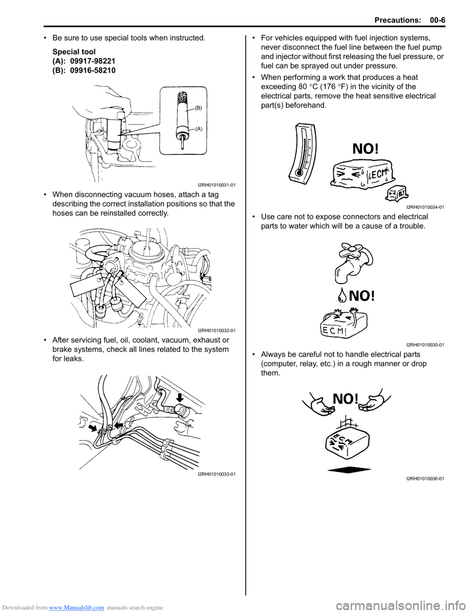
• Be sure to use special tools when instructed.Special tool
(A): 09917-98221
(B): 09916-58210
• When disconnecting vacuum hoses, attach a tag describing the correct installation positions so that the
hoses can be reinstalled correctly.
• After servicing fuel, oil, coolant, vacuum, exhaust or brake systems, check all lin es related to the system
for leaks. • For vehicles equipped with fuel injection systems,
never disconnect the fuel line between the fuel pump
and injector without first releasing the fuel pressure, or
fuel can be sprayed out under pressure.
• When performing a work that produces a heat exceeding 80 °C (176 ° F) in the vicinity of the
electrical parts, remove t he heat sensitive electrical
part(s) beforehand.
• Use care not to expose connectors and electrical parts to water which will be a cause of a trouble.
• Always be careful not to handle electrical parts (computer, relay, etc.) in a rough manner or drop
them.
I2RH01010031-01
I2RH01010032-01
I2RH01010033-01
I2RH01010034-01
I2RH01010035-01
I2RH01010036-01
Page 41 of 1496
Downloaded from www.Manualslib.com manuals search engine Maintenance and Lubrication: 0B-11
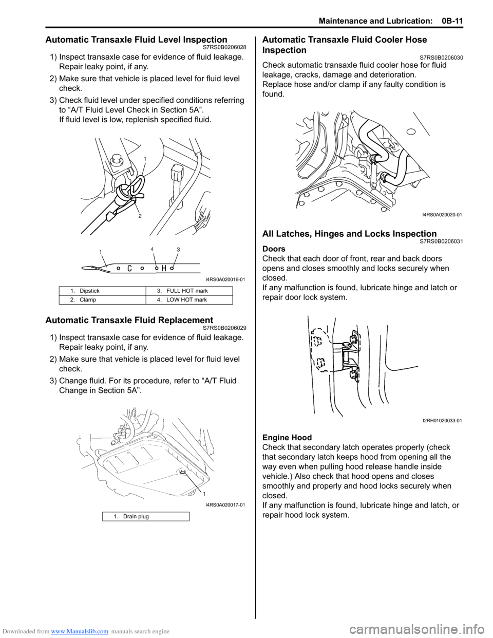
Automatic Transaxle Fluid Level InspectionS7RS0B0206028
1) Inspect transaxle case for evidence of fluid leakage.Repair leaky point, if any.
2) Make sure that vehicle is placed level for fluid level check.
3) Check fluid level under spec ified conditions referring
to “A/T Fluid Level Check in Section 5A”.
If fluid level is low, replenish specified fluid.
Automatic Transaxle Fluid ReplacementS7RS0B0206029
1) Inspect transaxle case for evidence of fluid leakage. Repair leaky point, if any.
2) Make sure that vehicle is placed level for fluid level check.
3) Change fluid. For its procedure, refer to “A/T Fluid Change in Section 5A”.
Automatic Transaxle Fluid Cooler Hose
Inspection
S7RS0B0206030
Check automatic transaxle fluid cooler hose for fluid
leakage, cracks, damage and deterioration.
Replace hose and/or clamp if any faulty condition is
found.
All Latches, Hinges and Locks InspectionS7RS0B0206031
Doors
Check that each door of front, rear and back doors
opens and closes smoothly and locks securely when
closed.
If any malfunction is found, lubricate hinge and latch or
repair door lock system.
Engine Hood
Check that secondary latch operates properly (check
that secondary latch keeps hood from opening all the
way even when pulling hood release handle inside
vehicle.) Also check that hood opens and closes
smoothly and properly and hood locks securely when
closed.
If any malfunction is found, l ubricate hinge and latch, or
repair hood lock system.
1. Dipstick 3. FULL HOT mark
2. Clamp 4. LOW HOT mark
1. Drain plug
I4RS0A020016-01
I4RS0A020017-01
I4RS0A020020-01
I2RH01020033-01
Page 52 of 1496
Downloaded from www.Manualslib.com manuals search engine 1A-2 Engine General Information and Diagnosis:
• Be sure to read “Precautions for Electrical Circuit Service in Section 00” befo re inspection and observe
what is written there.
• ECM replacement: When substituting a known-good ECM, check for the
following conditions. Neglec ting this check may cause
damage to a known-good ECM.
– Resistance value of all relays, actuators is as specified respectively.
– MAP sensor, A/C refrigerant pressure sensor and TP sensor are in good condition and none of power
circuits of these sensors is shorted to ground.
• Communication of ECM, BCM, ABS/ESP ® control
module, combination meter, keyless start control
module, steering angle sensor (ESP ® model) and
TCM (A/T model), is esta blished by CAN (Controller
Area Network). (For more detail of CAN
communication for ECM, refer to “CAN
Communication System Description”). Therefore,
handle CAN communication line with care referring to
“Precaution for CAN Communication System in
Section 00”.
• Immobilizer transponder code registration after
replacing ECM
When ECM is replaced with new one or with another
one, make sure to register immobilizer transponder
code to ECM correctly according to “Procedure after
ECM Replacement in Section 10C”.Precautions of ECM Circuit InspectionS7RS0B1100003
• ECM connectors are waterproofed. Each terminal of the ECM connectors is sealed up with the grommet.
Therefore, when measuring ci rcuit voltage, resistance
and/or pulse signal at ECM connector, do not insert
the tester’s probe into th e sealed terminal at the
harness side. When measuring circuit voltage,
resistance and/or pulse signal at ECM connector,
connect the special tool to the ECM connectors. And,
insert the tester’s probe into the special tool’s
connectors at the harness side, and then measure
voltage, resistance and/or pulse signal. Or, ECM and
its circuits may be damaged by water.
• Wire colors of the special tool’s connectors are different from the ones of the ECM connectors.
However, the circuit arrangement of the special tool’s
connectors is same as the one of the ECM
connectors. Therefore, measure circuit voltage and
resistance by identifying the terminal location subject
to the measurement.
Precautions of Electric Throttle Body System
Calibration
S7RS0B1100004
After performing one of works described below, it is
necessary to re-register the completely closed throttle
valve reference position stored in memory of ECM. (For
detailed information, refer to “Description of Electric
Throttle Body System Calibration”.) For the procedure to
register such data in ECM, refer to “Electric Throttle
Body System Calibration in Section 1C”.
• To shut off backup power of ECM for such purposes of battery replacement or “DOME” fuse removal
• To erase DTCs P0122, P01 23, P0222, P0223, P2101,
P2102, P2103, P2111, P2112, P2113, P2119, P2123,
P2127, P2128, P2135 and/or P2138
• To replace ECM
• To replace throttle body and/or accelerator pedal position (APP) sensor assembly
General Description
Statement on Cleanliness and CareS7RS0B1101001
An automobile engine is a combination of many
machined, honed, polished and lapped surfaces with
tolerances that are measured in the thousands of an
millimeter (ten thous ands of an inch).
Accordingly, when any internal engine parts are
serviced, care and cleanliness are important.
It should be understood that proper cleaning and
protection of machined surfaces and friction areas is part
of the repair procedure. This is considered standard
shop practice even if not specifically stated.
• A liberal coating of engine oil should be applied to friction areas during assembly to protect and lubricate
the surfaces on initial operation. • Whenever valve train components, pistons, piston
rings, connecting rods, rod bearings, and crankshaft
journal bearings are removed for service, they should
be retained in order.
At the time of installation, they should be installed in
the same locations and with the same mating
surfaces as when removed.
• Battery cables should be disconnected before any major work is performed on the engine.
Failure to disconnect cables may result in damage to
wire harness or other electrical parts.
Page 306 of 1496
Downloaded from www.Manualslib.com manuals search engine 1D-21 Engine Mechanical:
Timing Chain Cover Removal and InstallationS7RS0B1406013
CAUTION!
• Keep working table, tools and hands clean while overhauling.
• Use special care to handle aluminum parts so as not to damage them.
• Do not expose removed parts to dust. Keep them always clean.
Removal
1) Remove engine assembly from vehicle referring to “Engine Assembly Removal and Installation”.
2) Remove water pump / generator drive belt referring to “Water Pump / Generator Drive Belt Removal and
Installation in Section 1J”.
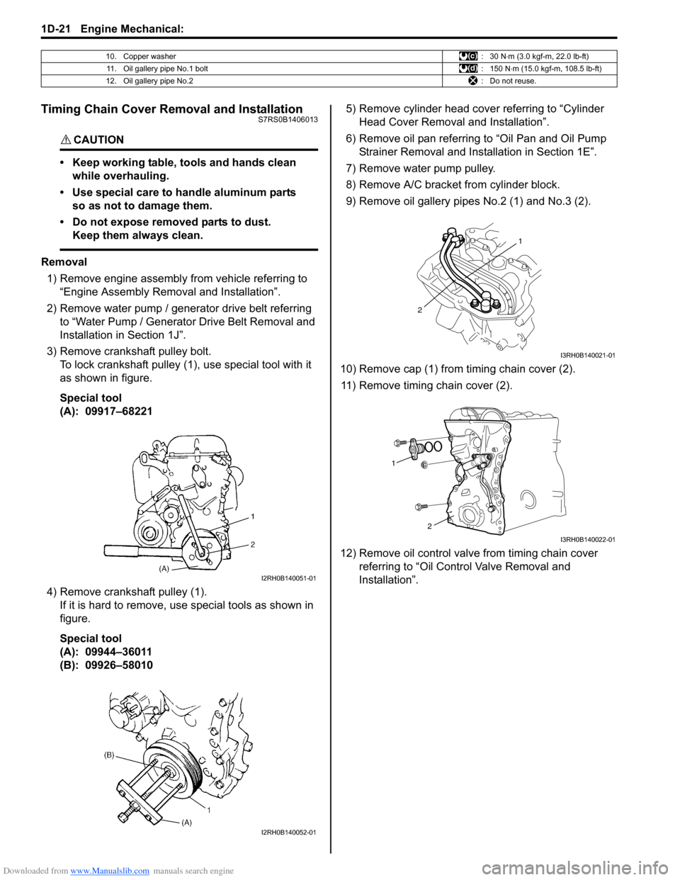
3) Remove crankshaft pulley bolt. To lock crankshaft pulley (1), use special tool with it
as shown in figure.
Special tool
(A): 09917–68221
4) Remove crankshaft pulley (1). If it is hard to remove, use special tools as shown in
figure.
Special tool
(A): 09944–36011
(B): 09926–58010 5) Remove cylinder head cove
r referring to “Cylinder
Head Cover Removal and Installation”.
6) Remove oil pan referring to “Oil Pan and Oil Pump
Strainer Removal and Inst allation in Section 1E”.
7) Remove water pump pulley.
8) Remove A/C bracket from cylinder block.
9) Remove oil gallery pipe s No.2 (1) and No.3 (2).
10) Remove cap (1) from timing chain cover (2). 11) Remove timing chain cover (2).
12) Remove oil control valve from timing chain cover referring to “Oil Cont rol Valve Removal and
Installation”.
10. Copper washer :30 N⋅m (3.0 kgf-m, 22.0 lb-ft)
11. Oil gallery pipe No.1 bolt : 150 N⋅m (15.0 kgf-m, 108.5 lb-ft)
12. Oil gallery pipe No.2 : Do not reuse.
I2RH0B140051-01
I2RH0B140052-01
1
2
I3RH0B140021-01
1 2
I3RH0B140022-01
Page 314 of 1496
Downloaded from www.Manualslib.com manuals search engine 1D-29 Engine Mechanical:
Camshaft, Tappet and Shim Removal and
Installation
S7RS0B1406021
CAUTION!
• Keep working table, tools and hands clean while overhauling.
• Use special care to handle aluminum parts so as not to damage them.
• Do not expose removed parts to dust. Keep them always clean.
Removal
1) Remove timing chain cover referring to “Timing Chain Cover Removal and Installation”.
2) Remove timing chain referring to “Timing Chain and Chain Tensioner Removal and Installation”.
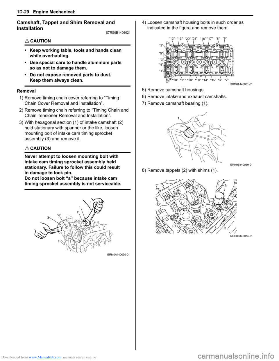
3) With hexagonal section (1) of intake camshaft (2) held stationary with spanner or the like, loosen
mounting bolt of intake cam timing sprocket
assembly (3) and remove it.
CAUTION!
Never attempt to loosen mounting bolt with
intake cam timing sprocket assembly held
stationary. Failure to fo llow this could result
in damage to lock pin.
Do not loosen bolt “a” because intake cam
timing sprocket assembly is not serviceable.
4) Loosen camshaft housing bolts in such order as indicated in the figure and remove them.
5) Remove camshaft housings.
6) Remove intake and exhaust camshafts.
7) Remove camshaft bearing (1).
8) Remove tappets (2) with shims (1).
3“a”
1
2
I3RM0A140030-01
“12”“13” “20”“21”
“16”“17” “8” “9”
“2”
“5” “3”
“4”
“1”
“10”“11”“18”
“19” “14” “15” “6” “7”
I3RM0A140031-01
1
I3RH0B140039-01
I2RH0B140074-01
Page 323 of 1496
Downloaded from www.Manualslib.com manuals search engine Engine Mechanical: 1D-38
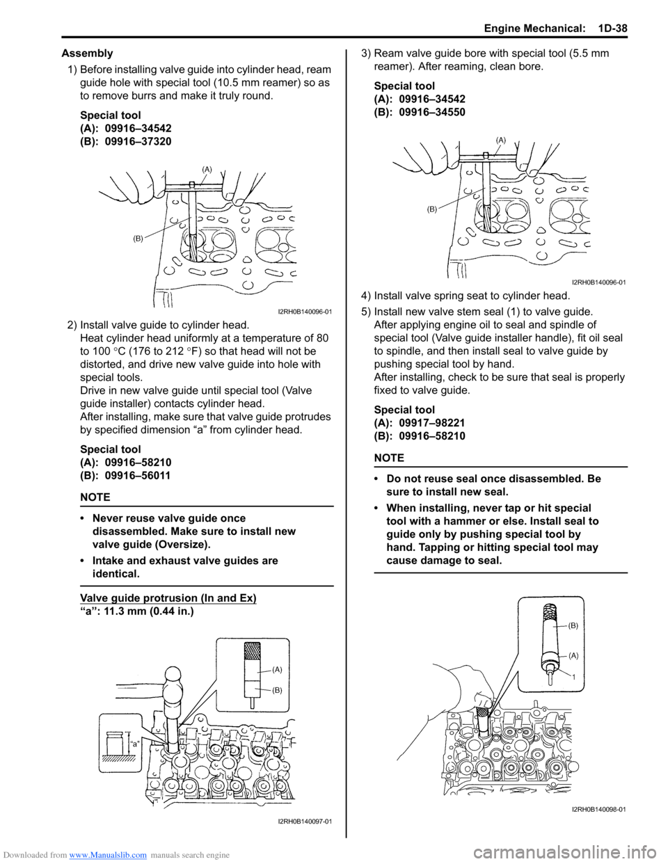
Assembly1) Before installing valve guide into cylinder head, ream
guide hole with special tool (10.5 mm reamer) so as
to remove burrs and make it truly round.
Special tool
(A): 09916–34542
(B): 09916–37320
2) Install valve guide to cylinder head. Heat cylinder head uniformly at a temperature of 80
to 100 °C (176 to 212 °F) so that head will not be
distorted, and drive new valve guide into hole with
special tools.
Drive in new valve guide until special tool (Valve
guide installer) contacts cylinder head.
After installing, ma ke sure that valve guide pr otrudes
by specified dimension “a” from cylinder head.
Special tool
(A): 09916–58210
(B): 09916–56011
NOTE
• Never reuse valve guide once disassembled. Make sure to install new
valve guide (Oversize).
• Intake and exhaust valve guides are identical.
Valve guide protrusion (In and Ex)
“a”: 11.3 mm (0.44 in.) 3) Ream valve guide bore with special tool (5.5 mm
reamer). After reaming, clean bore.
Special tool
(A): 09916–34542
(B): 09916–34550
4) Install valve spring seat to cylinder head.
5) Install new valve stem seal (1) to valve guide. After applying engine oil to seal and spindle of
special tool (Valve guide installer handle), fit oil seal
to spindle, and then install seal to valve guide by
pushing special tool by hand.
After installing, check to be sure that seal is properly
fixed to valve guide.
Special tool
(A): 09917–98221
(B): 09916–58210
NOTE
• Do not reuse seal once disassembled. Be sure to install new seal.
• When installing, never tap or hit special tool with a hammer or else. Install seal to
guide only by pushing special tool by
hand. Tapping or hitting special tool may
cause damage to seal.
I2RH0B140096-01
I2RH0B140097-01
I2RH0B140096-01
I2RH0B140098-01
Page 330 of 1496
Downloaded from www.Manualslib.com manuals search engine 1D-45 Engine Mechanical:
Pistons, Piston Rings, Connecting Rods and
Cylinders Removal and Installation
S7RS0B1406030
Removal1) Remove engine assembly from vehicle referring to “Engine Assembly Removal and Installation”.
2) Remove cylinder head referring to “Valves and Cylinder Head Removal and Installation”.
3) Mark cylinder number on all pistons, connecting rods
and connecting rod caps using silver pencil or quick
drying paint.
4) Remove rod bearing caps.
5) Decarbonize top of cylinder bore before removing piston from cylinder.
6) Push piston and connecting rod assembly out through the top of cylinder bore.
Installation 1) Apply engine oil to pistons, rings, cylinder walls, connecting rod bearings and crank pins.
NOTE
Do not apply oil between connecting rod and
bearing or between bearing cap and bearing.
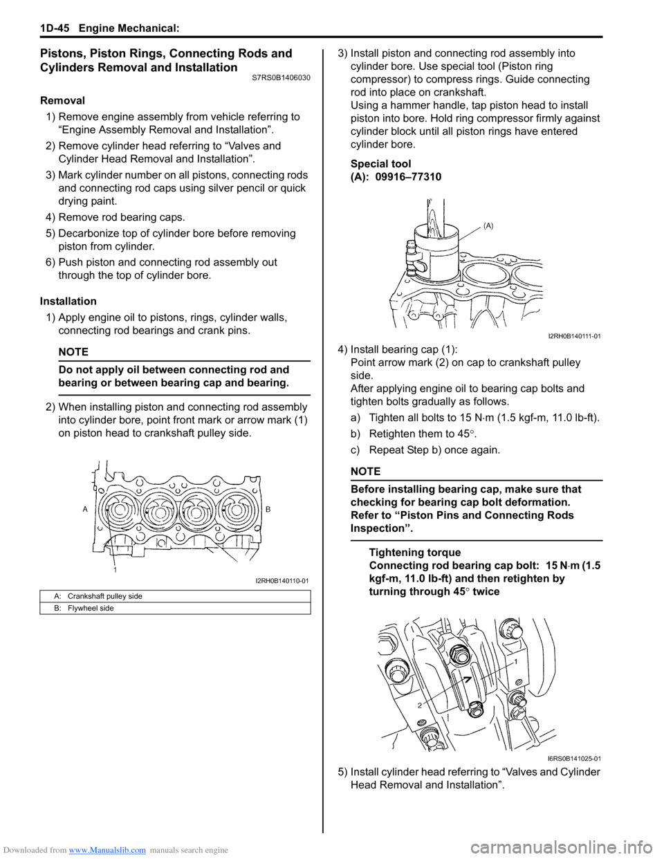
2) When installing piston and connecting rod assembly into cylinder bore, point front mark or arrow mark (1)
on piston head to crankshaft pulley side. 3) Install piston and connecting rod assembly into
cylinder bore. Use special tool (Piston ring
compressor) to compress rings. Guide connecting
rod into place on crankshaft.
Using a hammer handle, tap piston head to install
piston into bore. Hold ring compressor firmly against
cylinder block until all piston rings have entered
cylinder bore.
Special tool
(A): 09916–77310
4) Install bearing cap (1): Point arrow mark (2) on cap to crankshaft pulley
side.
After applying engine oil to bearing cap bolts and
tighten bolts gradually as follows.
a) Tighten all bolts to 15 N ⋅m (1.5 kgf-m, 11.0 lb-ft).
b) Retighten them to 45 °.
c) Repeat Step b) once again.
NOTE
Before installing bearing cap, make sure that
checking for bearing cap bolt deformation.
Refer to “Piston Pins and Connecting Rods
Inspection”.
Tightening torque
Connecting rod bearing cap bolt: 15 N ⋅m (1.5
kgf-m, 11.0 lb-ft) and then retighten by
turning through 45 ° twice
5) Install cylinder head referring to “Valves and Cylinder Head Removal and Installation”.
A: Crankshaft pulley side
B: Flywheel side
I2RH0B140110-01
I2RH0B140111-01
I6RS0B141025-01
Page 351 of 1496
Downloaded from www.Manualslib.com manuals search engine Engine Mechanical: 1D-66
Special Tools and Equipment
Recommended Service MaterialS7RS0B1408001
NOTE
Required service material is also described in the following.
“Timing Chain Cover Components”
“Timing Chain and Chain Tensioner Components”
“Camshaft, Tappet and Shim Components”
“Valves and Cylinder Head Components”
“Pistons, Piston Rings, Connecting Rods and Cylinders Components”
“Main Bearings, Crankshaft and Cylinder Block Components”
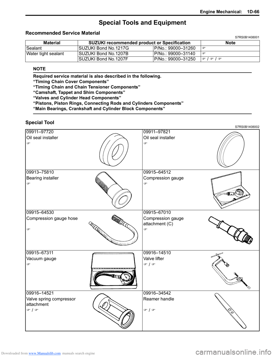
Special ToolS7RS0B1408002
Material SUZUKI recommended product or Specification Note
Sealant SUZUKI Bond No.1217G P/No.: 99000–31260�)
Water tight sealant SUZUKI Bond No.1207B P/No.: 99000–31140�)
SUZUKI Bond No.1207F P/No.: 99000–31250�) / �) / �)
09911–97720 09911–97821
Oil seal installer Oil seal installer
�)�)
09913–75810 09915–64512
Bearing installer Compression gauge
�)�)
09915–64530 09915–67010
Compression gauge hose Compression gauge
attachment (C)
�)�)
09915–67311 09916–14510
Vacuum gauge Valve lifter
�)�) / �)
09916–14521 09916–34542
Valve spring compressor
attachment Reamer handle
�) / �)�) / �)
Page 352 of 1496
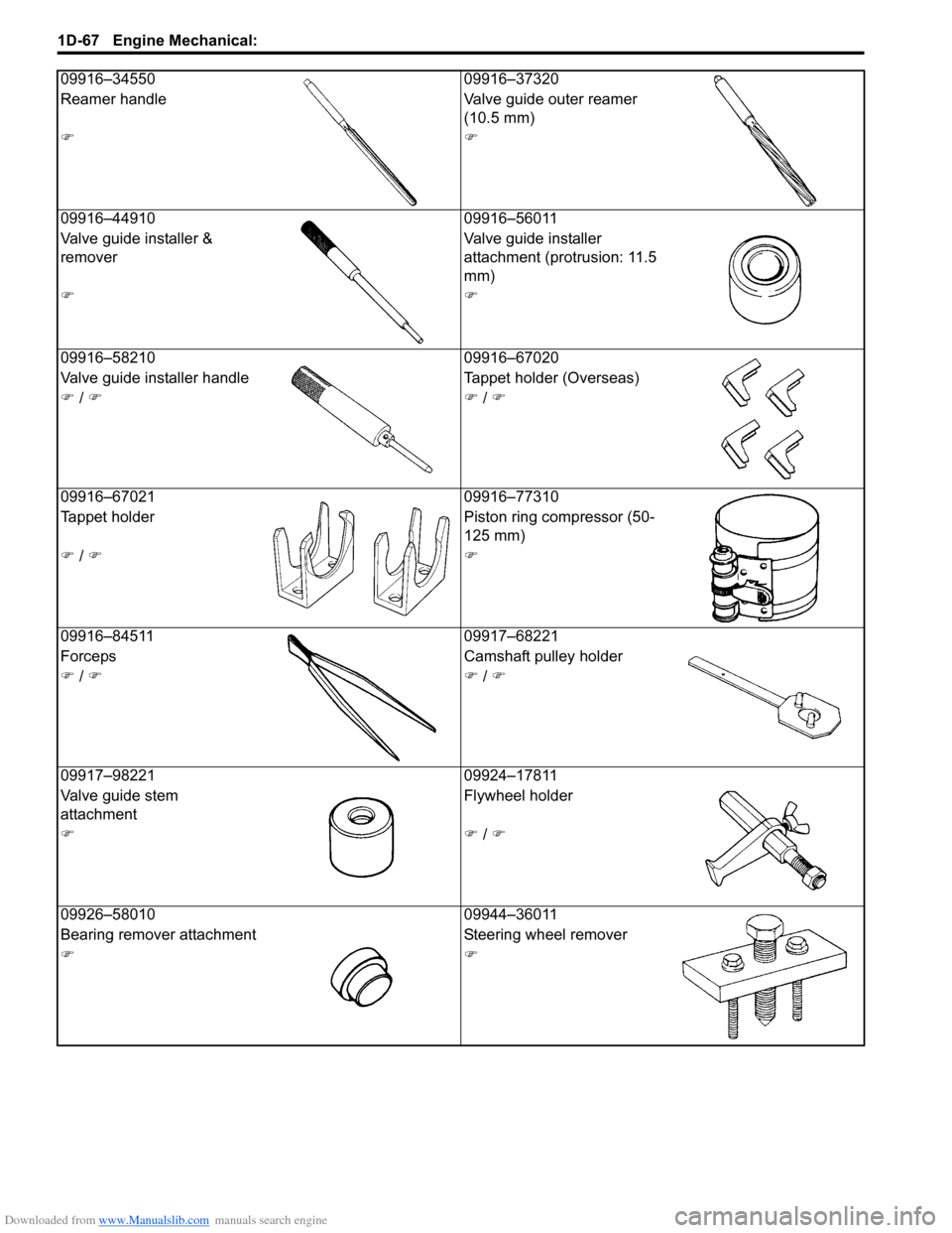
Downloaded from www.Manualslib.com manuals search engine 1D-67 Engine Mechanical:
09916–3455009916–37320
Reamer handle Valve guide outer reamer
(10.5 mm)
�)�)
09916–44910 09916–56011
Valve guide installer &
remover Valve guide installer
attachment (protrusion: 11.5
mm)
�)�)
09916–58210 09916–67020
Valve guide installer handle Tappet holder (Overseas)
�) / �)�) / �)
09916–67021 09916–77310
Tappet holder Piston ring compressor (50-
125 mm)
�) / �)�)
09916–84511 09917–68221
Forceps Camshaft pulley holder
�) / �)�) / �)
09917–98221 09924–17811
Valve guide stem
attachment Flywheel holder
�)�) / �)
09926–58010 09944–36011
Bearing remover attachment Steering wheel remover
�)�)
Page 431 of 1496
Downloaded from www.Manualslib.com manuals search engine Precautions: 2-1
Suspension
Precautions
Precautions
Precautions on SuspensionS7RS0B2000001
Emergency Flat Tire Repair Kit handle Warning
Refer to “Warning for Handling Emergency Flat Tire Repair Kit in Section 00”.
Suspension Caution
Refer to “Suspension Caution in Section 00”.
Wheels and Tires Caution
Refer to “Wheels and Tires Caution in Section 00”.
General Precautions
Refer to “General Precautions in Section 00”.
Vehicle Lifting Points
Refer to “Vehicle Lifting Points in Section 0A”.
Fastener Caution
Refer to “Fastener Caution in Section 00”.
Fastener Information
Refer to “Fasteners Information in Section 0A”.
Brake Caution
Refer to “Brake Caution in Section 00”.