clock SUZUKI SWIFT 2017 5.G User Guide
[x] Cancel search | Manufacturer: SUZUKI, Model Year: 2017, Model line: SWIFT, Model: SUZUKI SWIFT 2017 5.GPages: 336, PDF Size: 6.24 MB
Page 174 of 336
5-47OTHER CONTROLS AND EQUIPMENT
74LH0-74E
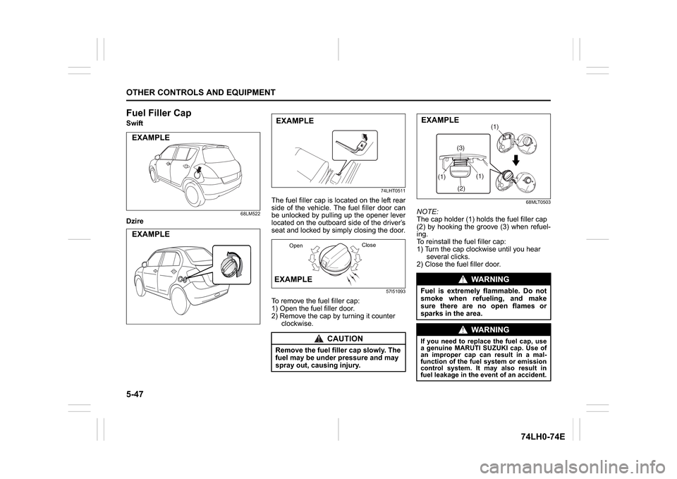
Fuel Filler CapSwift
68LM522
Dzire
74LHT0511
The fuel filler cap is located on the left rear
side of the vehicle. The fuel filler door can
be unlocked by pulling up the opener lever
located on the outboard side of the driver’s
seat and locked by simply closing the door.
57l51093
To remove the fuel filler cap:
1) Open the fuel filler door.
2) Remove the cap by turning it counter
clockwise.
68MLT0503
NOTE:
The cap holder (1) holds the fuel filler cap
(2) by hooking the groove (3) when refuel-
ing.
To reinstall the fuel filler cap:
1) Turn the cap clockwise until you hear
several clicks.
2) Close the fuel filler door.
EXAMPLEEXAMPLE
CAUTION
Remove the fuel filler cap slowly. The
fuel may be under pressure and may
spray out, causing injury.EXAMPLEEXAMPLE
OpenClose
WA R N I N G
Fuel is extremely flammable. Do not
smoke when refueling, and make
sure there are no open flames or
sparks in the area.
WA R N I N G
If you need to replace the fuel cap, use
a genuine MARUTI SUZUKI cap. Use of
an improper cap can result in a mal-
function of the fuel system or emission
control system. It may also result in
fuel leakage in the event of an accident.
(1)
(2)(3)(1)
(1)
EXAMPLE
Page 181 of 336
5-54
OTHER CONTROLS AND EQUIPMENT
74LH0-74E
(with spare tyre)
74LHT0528
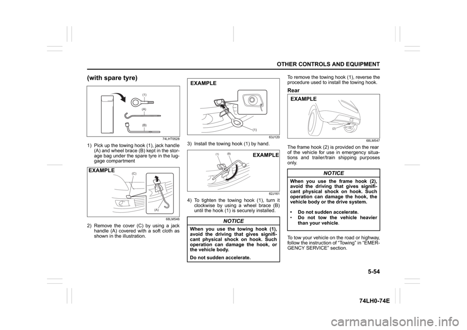
1) Pick up the towing hook (1), jack handle
(A) and wheel brace (B) kept in the stor-
age bag under the spare tyre in the lug-
gage compartment
68LM546
2) Remove the cover (C) by using a jack
handle (A) covered with a soft cloth as
shown in the illustration.
63J120
3) Install the towing hook (1) by hand.
62J161
4) To tighten the towing hook (1), turn it
clockwise by using a wheel brace (B)
until the hook (1) is securely installed.To remove the towing hook (1), reverse the
procedure used to install the towing hook.
Rear
68LM547
The frame hook (2) is provided on the rear
of the vehicle for use in emergency situa-
tions and trailer/train shipping purposes
only.
To tow your vehicle on the road or highway,
follow the instruction of “Towing” in “EMER-
GENCY SERVICE” section.
(1)(A)(B)
(C)
(A)
EXAMPLE
NOTICE
When you use the towing hook (1),
avoid the driving that gives signifi-
cant physical shock on hook. Such
operation can damage the hook, or
the vehicle body.
Do not sudden accelerate.
(1)
EXAMPLE
(1)
(B)
EXAMPLE
NOTICE
When you use the frame hook (2),
avoid the driving that gives signifi-
cant physical shock on hook. Such
operation can damage the hook, the
vehicle body or the drive system.
Do not sudden accelerate.
Do not tow the vehicle heavier
than your vehicle.
(2)
EXAMPLE
Page 200 of 336
7-9INSPECTION AND MAINTENANCE
74LH0-74E
Replace the Oil Filter(For Petrol Engine Model)
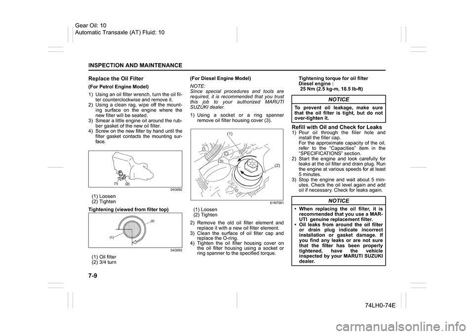
1) Using an oil filter wrench, turn the oil fil-
ter counterclockwise and remove it.
2) Using a clean rag, wipe off the mount-
ing surface on the engine where the
new filter will be seated.
3) Smear a little engine oil around the rub-
ber gasket of the new oil filter.
4) Screw on the new filter by hand until the
filter gasket contacts the mounting sur-
face.
54G092
(1) Loosen
(2) Tighten
Tightening (viewed from filter top)
54G093
(1) Oil filter
(2) 3/4 turn(For Diesel Engine Model)
NOTE:
Since special procedures and tools are
required, it is recommended that you trust
this job to your authorized MARUTI
SUZUKI dealer.
1) Using a socket or a ring spanner
remove oil filter housing cover (3).
61M7001
(1) Loosen
(2) Tighten
2) Remove the old oil filter element and
replace it with a new oil filter element.
3) Clean the surface of oil filter cap and
replace the O-ring.
4) Tighten the oil filter housing cover on
the oil filter housing using a socket or
ring spanner to the specified torque.Tightening torque for oil filter
Diesel engine :
25 Nm (2.5 kg-m, 18.5 lb-ft)
Refill with Oil and Check for Leaks1) Pour oil through the filler hole and
install the filler cap.
For the approximate capacity of the oil,
refer to the “Capacities” item in the
“SPECIFICATIONS” section.
2) Start the engine and look carefully for
leaks at the oil filter and drain plug. Run
the engine at various speeds for at least
5 minutes.
3) Stop the engine and wait about 5 min-
utes. Check the oil level again and add
oil if necessary. Check for leaks again.
(1)
(3)
(2)
NOTICE
To prevent oil leakage, make sure
that the oil filter is tight, but do not
over-tighten it.
NOTICE
When replacing the oil filter, it is
recommended that you use a MAR-
UTI genuine replacement filter.
Oil leaks from around the oil filter
or drain plug indicate incorrect
installation or gasket damage. If
you find any leaks or are not sure
that the filter has been properly
tightened, have the vehicle
inspected by your MARUTI SUZUKI
dealer.
Gear Oil: 10
Automatic Transaxle (AT) Fluid: 10
Page 202 of 336
7-11INSPECTION AND MAINTENANCE
74LH0-74E
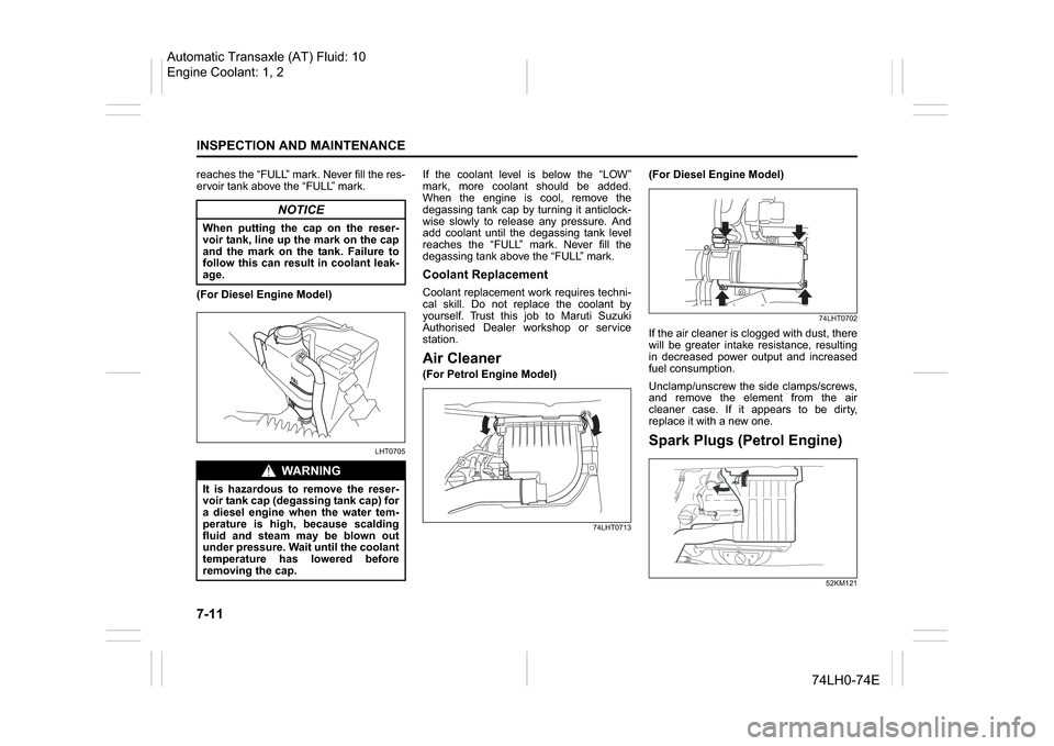
reaches the “FULL” mark. Never fill the res-
ervoir tank above the “FULL” mark.
(For Diesel Engine Model)
LHT0705
If the coolant level is below the “LOW”
mark, more coolant should be added.
When the engine is cool, remove the
degassing tank cap by turning it anticlock-
wise slowly to release any pressure. And
add coolant until the degassing tank level
reaches the “FULL” mark. Never fill the
degassing tank above the “FULL” mark.Coolant ReplacementCoolant replacement work requires techni-
cal skill. Do not replace the coolant by
yourself. Trust this job to Maruti Suzuki
Authorised Dealer workshop or service
station.Air Cleaner(For Petrol Engine Model)
74LHT0713
(For Diesel Engine Model)
74LHT0702
If the air cleaner is clogged with dust, there
will be greater intake resistance, resulting
in decreased power output and increased
fuel consumption.
Unclamp/unscrew the side clamps/screws,
and remove the element from the air
cleaner case. If it appears to be dirty,
replace it with a new one.Spark Plugs (Petrol Engine)
52KM121
NOTICE
When putting the cap on the reser-
voir tank, line up the mark on the cap
and the mark on the tank. Failure to
follow this can result in coolant leak-
age.
WA R N I N G
It is hazardous to remove the reser-
voir tank cap (degassing tank cap) for
a diesel engine when the water tem-
perature is high, because scalding
fluid and steam may be blown out
under pressure. Wait until the coolant
temperature has lowered before
removing the cap.
Automatic Transaxle (AT) Fluid: 10
Engine Coolant: 1, 2
Page 217 of 336
7-26
INSPECTION AND MAINTENANCE
74LH0-74E
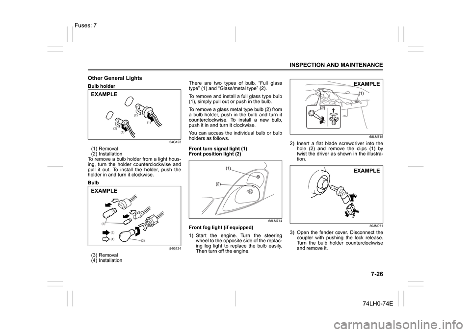
Other General LightsBulb holder
54G123
(1) Removal
(2) Installation
To remove a bulb holder from a light hous-
ing, turn the holder counterclockwise and
pull it out. To install the holder, push the
holder in and turn it clockwise.
Bulb
54G124
(3) Removal
(4) InstallationThere are two types of bulb, “Full glass
type” (1) and “Glass/metal type” (2).
To remove and install a full glass type bulb
(1), simply pull out or push in the bulb.
To remove a glass metal type bulb (2) from
a bulb holder, push in the bulb and turn it
counterclockwise. To install a new bulb,
push it in and turn it clockwise.
You can access the individual bulb or bulb
holders as follows.
Front turn signal light (1)
Front position light (2)
68LM714
Front fog light (if equipped)
1) Start the engine. Turn the steering
wheel to the opposite side of the replac-
ing fog light to replace the bulb easily.
Then turn off the engine.
68LM715
2) Insert a flat blade screwdriver into the
hole (2) and remove the clips (1) by
twist the driver as shown in the illustra-
tion.
80JM071
3) Open the fender cover. Disconnect the
coupler with pushing the lock release.
Turn the bulb holder counterclockwise
and remove it.
(1)
(1) (2)(2)
EXAMPLE
(1)
(2) (3)
(4)
EXAMPLE
EXAMPLEEXAMPLE
Fuses: 7
Page 224 of 336
8-1EMERGENCY SERVICE
74LH0-74E
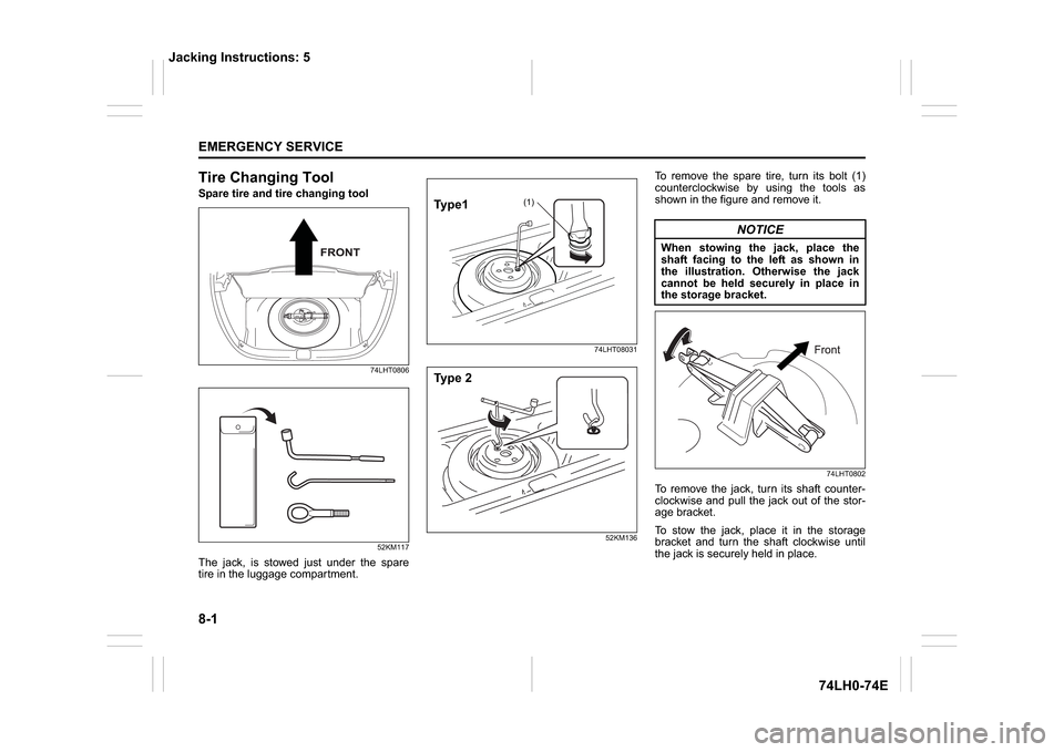
Tire Changing ToolSpare tire and tire changing tool
74LHT0806
52KM117
The jack, is stowed just under the spare
tire in the luggage compartment.
74LHT08031
52KM136
To remove the spare tire, turn its bolt (1)
counterclockwise by using the tools as
shown in the figure and remove it.
74LHT0802
To remove the jack, turn its shaft counter-
clockwise and pull the jack out of the stor-
age bracket.
To stow the jack, place it in the storage
bracket and turn the shaft clockwise until
the jack is securely held in place.
(1)
Ty p e 1Ty p e 2
NOTICE
When stowing the jack, place the
shaft facing to the left as shown in
the illustration. Otherwise the jack
cannot be held securely in place in
the storage bracket.
Jacking Instructions: 5
Page 225 of 336
8-2
EMERGENCY SERVICE
74LH0-74E
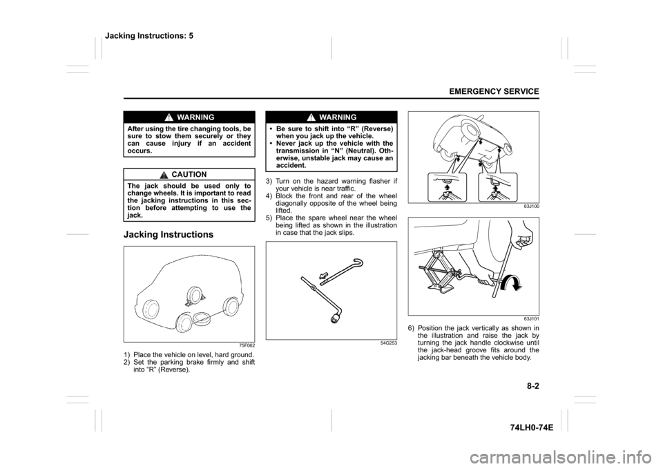
Jacking Instructions
75F062
1) Place the vehicle on level, hard ground.
2) Set the parking brake firmly and shift
into “R” (Reverse).3) Turn on the hazard warning flasher if
your vehicle is near traffic.
4) Block the front and rear of the wheel
diagonally opposite of the wheel being
lifted.
5) Place the spare wheel near the wheel
being lifted as shown in the illustration
in case that the jack slips.
54G25363J100
63J101
6) Position the jack vertically as shown in
the illustration and raise the jack by
turning the jack handle clockwise until
the jack-head groove fits around the
jacking bar beneath the vehicle body.
WA R N I N G
After using the tire changing tools, be
sure to stow them securely or they
can cause injury if an accident
occurs.
CAUTION
The jack should be used only to
change wheels. It is important to read
the jacking instructions in this sec-
tion before attempting to use the
jack.
WA R N I N G
Be sure to shift into “R” (Reverse)
when you jack up the vehicle.
Never jack up the vehicle with the
transmission in “N” (Neutral). Oth-
erwise, unstable jack may cause an
accident.
Jacking Instructions: 5
Page 231 of 336
8-8
EMERGENCY SERVICE
74LH0-74E
For Diesel
65D350D
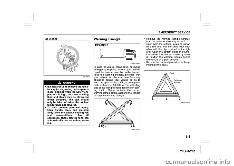
Warning Triangle
MHO-07-001
In case of vehicle break-down or during
emergency stopping, where, your vehicle
could become a potential traffic hazard,
keep the warning triangle, provided with
your vehicle, on the road free from any
obstacles behind your vehicle so as to
warn the approaching traffic, at an approxi-
mate distance of 50-100 m. The reflecting
side of the triangle should face the on com-
ing traffic. Please activate the hazard
warning lamps before alighting the vehicle
to keep the warning triangle.
MHO-07-014
Remove the warning triangle carefully
from the cover as shown by arrow 1.
Open both the reflector arms as shown
by arrow and lock the arms with each
other with the clip provided in the right
arm. Open the bottom stand in counter
clock-wise direction as shown by arrow
3. Position the warning triangle behind
the vehicle on a plain surface.
Reverse the removal procedure for keep-
ing inside the cover.
MHO-07-014
WA R N I N G
It is hazardous to remove the radia-
tor cap (or degassing tank cap for a
diesel engine) when the water tem-
perature is high, because scalding
fluid and steam may be blown out
under pressure. The cap should
only be taken off when the coolant
temperature has lowered.
To help prevent personal injury,
keep hands, tools and clothing
away from the engine cooling fan
and air-conditioner fan (if
equipped). These electric fans can
automatically turn on without warn-
ing.
EXAMPLE