steering lock SUZUKI SWIFT 2017 5.G User Guide
[x] Cancel search | Manufacturer: SUZUKI, Model Year: 2017, Model line: SWIFT, Model: SUZUKI SWIFT 2017 5.GPages: 336, PDF Size: 6.24 MB
Page 120 of 336

4-3DRIVING TIPS
67LH3-74E
Keep the air cleaner clean
74LHM0404
If the air cleaner is clogged with dust, there
will be greater intake resistance, resulting
in decreased power output and increased
fuel consumption.
Keep weight to a minimum
Heavier the load, more fuel the vehicle
consumes. Take out any luggage or cargo
when it is not necessary.
Keep tire pressures correct
Underinflation of the tires can waste fuel
due to increased running resistance of the
tires. Keep your tires inflated to the correct
pressure shown on the label on the driver’s
door lock pillar.
Highway DrivingWhen driving at high speeds, pay attention
to the following:
Stopping distance progressivelyincreases with vehicle speed. Apply the
brakes far enough ahead of the stopping
point to allow for the extra stopping dis-
tance.
On rainy days, hydroplaning can occur. Hydroplaning is the loss of direct contact
between the road surface and the vehi-
cle’s tires due to a water film forming
between them. Steering or braking the
vehicle while hydroplaning can be very
difficult, and loss of control can occur.
Keep speed down when the road sur-
face is wet.
At high speeds, the vehicle may be affected by side winds. Therefore,
reduce speed and be prepared for unex-
pected buffeting, which can occur at the
exits of tunnels, when passing by a cut
of a hill, or when being overtaken by
large vehicles, etc.
Driving on Hills
74LHM0405
When climbing steep hills, the vehicle
may begin to slow down and show a lack
of power. If this happens, you should
shift to a lower gear so that the engine
will again be operating in its normal
power range. Shift rapidly to prevent the
vehicle from losing momentum.
When driving down a hill, the engine should be used for braking by shifting to
next lower gear.
EXAMPLE
R
N
D
-
M+
EXAMPLE
Page 188 of 336

6-5VEHICLE LOADING AND TOWING
74LH0-74E
A: 2WD VEHICLES WITH MANUAL
TRANSAXLE OR AUTOMATIC
TRANSAXLE OR AUTO GEAR
SHIFT1) Secure the front wheels on a towing
dolly according to the instructions pro-
vided by the dolly manufacturer.
2) Release the parking brake.
NOTICE
The steering column is not strong
enough to withstand shocks trans-
mitted from the front wheels during
towing. Always unlock the steering
wheel before towing. TOWING METHOD AFROM THE FRONT:
FRONT WHEELS ON A DOLLY
AND REAR WHEELS ON THE GROUND
B: 2WD VEHICLES WITH MANUAL TRANSAXLE OR AUTO GEAR SHIFT1) Shift the manual transaxle lever into neutral.
2) Turn the ignition key to the “ACC” position or change the ignition mode to the “ACC” to
unlock the steering wheel.
3) Release the parking brake.
ACC
N
TOWING METHOD BFROM THE FRONT:
FRONT WHEELS ON THE GROUND
Page 208 of 336

7-17INSPECTION AND MAINTENANCE
74LH0-74E
Pedal to floor carpet minimum dis-
tance “a”: 68 mm (2.7 in.)
With the engine running, measure the dis-
tance between the brake pedal and floor
carpet when the pedal is depressed with
approximately 30 kg (66 lbs) of force. The
minimum distance required is as specified.
Since your vehicle’s brake system is self-
adjusting, there is no need for pedal
adjustment.
If the pedal to floor carpet distance as
measured above is less than the minimum
distance required, have your vehicle
inspected by your MARUTI SUZUKI
dealer.
NOTE:
When measuring the distance between the
brake pedal and floor carpet, be sure not to
include the floor mat or rubber on the floor
carpet in your measurement.
60G104S
Parking Brake
54G109
Ratchet tooth specification “b”:
4th – 9th
Lever pull force (1):
200 N (20 kg, 44 lbs)
Check the parking brake for proper adjust-
ment by counting the number of clicks
made by the ratchet teeth as you slowly
pull up on the parking brake lever to thepoint of full engagement. The parking
brake lever should stop between the speci-
fied ratchet teeth and the rear wheels
should be securely locked. If the parking
brake is not properly adjusted or the
brakes drag after the lever has been fully
released, have the parking brake inspected
and/or adjusted by your MARUTI SUZUKI
dealer.
Steering
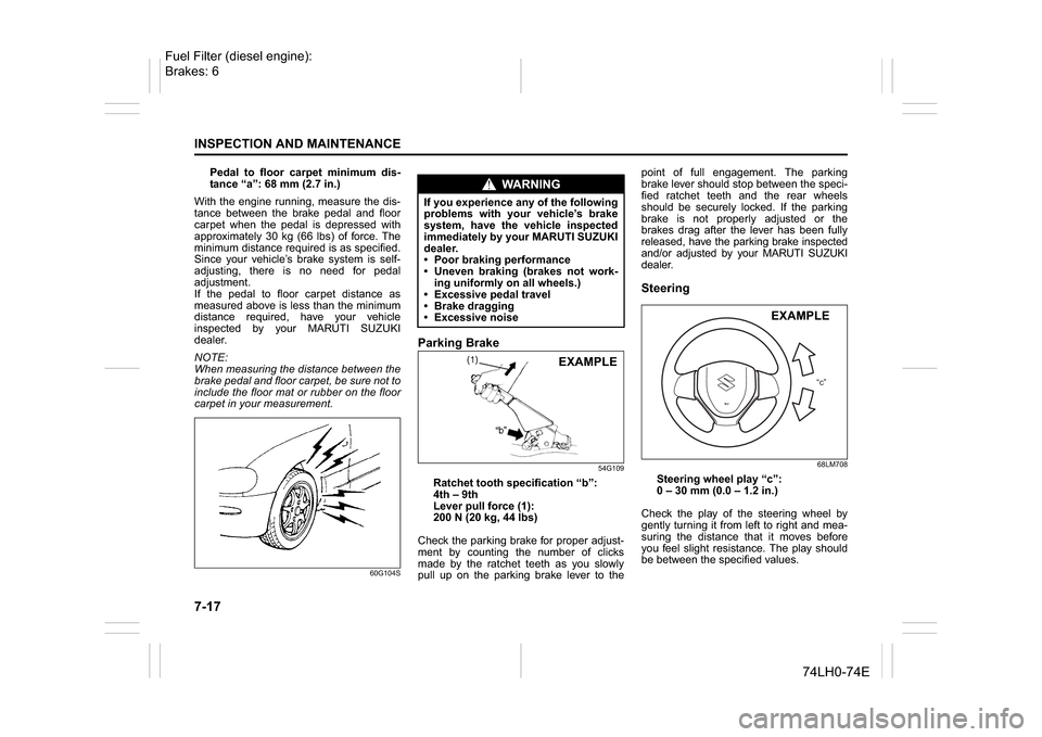
68LM708
Steering wheel play “c”:
0 – 30 mm (0.0 – 1.2 in.)
Check the play of the steering wheel by
gently turning it from left to right and mea-
suring the distance that it moves before
you feel slight resistance. The play should
be between the specified values.
WA R N I N G
If you experience any of the following
problems with your vehicle’s brake
system, have the vehicle inspected
immediately by your MARUTI SUZUKI
dealer.
Poor braking performance
Uneven braking (brakes not work-
ing uniformly on all wheels.)
Excessive pedal travel
Brake dragging
Excessive noise
EXAMPLE
“c”
EXAMPLE
Fuel Filter (diesel engine):
Brakes: 6
Page 214 of 336

7-23INSPECTION AND MAINTENANCE
74LH0-74E
The main fuse, primary fuses and some of
the individual fuses are located in the
engine compartment. If the main fuse
blows, no electrical component will func-
tion. If a primary fuse blows, no electrical
component in the corresponding load
group will function. When replacing the
main fuse, a primary fuse or an individual
fuse, use a MARUTI genuine replacement.
To remove a fuse, use the fuse puller pro-
vided in the fuse box. The amperage of
each fuse is shown in the back of the fuse
box cover.
60G111
NOTE:
Make sure that the fuse box always carries
spare fuses.Fuses under the Dash Board
74LHT0711
EXAMPLE
BLOWNOK
WA R N I N G
If the main fuse or a primary fuse
blows, be sure to have your vehicle
inspected by an authorized MARUTI
SUZUKI dealer. Always use a genuine
MARUTI replacement. Never use a
substitute such as a wire even for a
temporary repair, or extensive electri-
cal damage and a fire can result.EXAMPLE
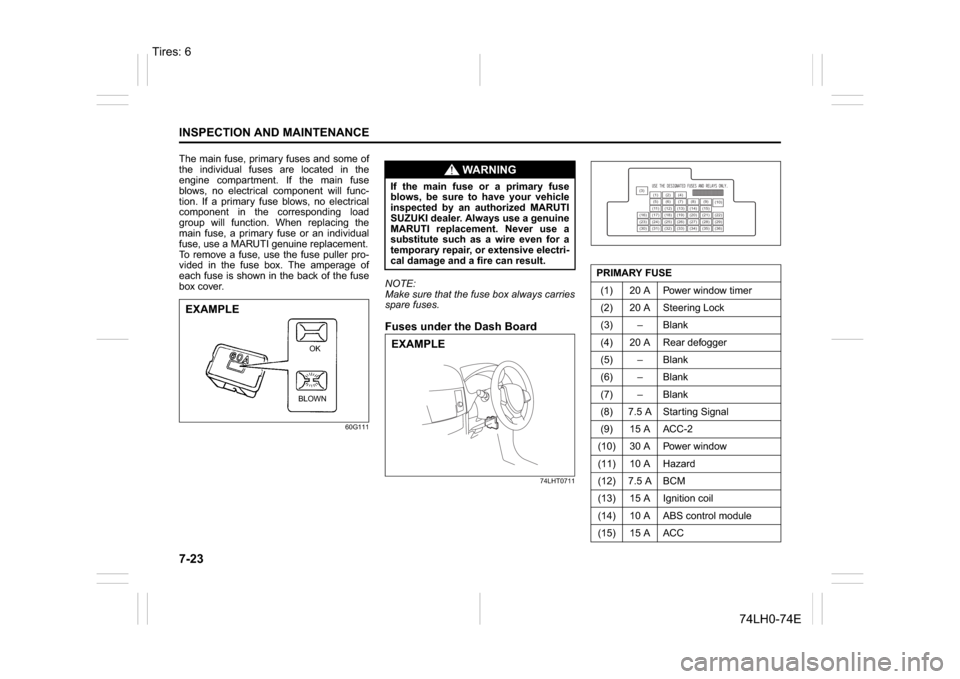
PRIMARY FUSE
(1) 20 A Power window timer
(2) 20 A Steering Lock
(3) – Blank
(4) 20 A Rear defogger
(5) – Blank
(6) – Blank
(7) – Blank
(8) 7.5 A Starting Signal
(9) 15 A ACC-2
(10) 30 A Power window
(11) 10 A Hazard
(12) 7.5 A BCM
(13) 15 A Ignition coil
(14) 10 A ABS control module
(15) 15 A ACC
(3)
(12)(10)
(13)
(36) (1) (2) (4)
(5)(6)
(7) (8)(9)
(11) (14) (15)
(16) (17) (18) (19) (20) (21) (22)
(23) (24) (25) (26) (27) (28) (29)
(30) (31) (32) (33) (34) (35)
Tires: 6
Page 217 of 336

7-26
INSPECTION AND MAINTENANCE
74LH0-74E
Other General LightsBulb holder
54G123
(1) Removal
(2) Installation
To remove a bulb holder from a light hous-
ing, turn the holder counterclockwise and
pull it out. To install the holder, push the
holder in and turn it clockwise.
Bulb
54G124
(3) Removal
(4) InstallationThere are two types of bulb, “Full glass
type” (1) and “Glass/metal type” (2).
To remove and install a full glass type bulb
(1), simply pull out or push in the bulb.
To remove a glass metal type bulb (2) from
a bulb holder, push in the bulb and turn it
counterclockwise. To install a new bulb,
push it in and turn it clockwise.
You can access the individual bulb or bulb
holders as follows.
Front turn signal light (1)
Front position light (2)
68LM714
Front fog light (if equipped)
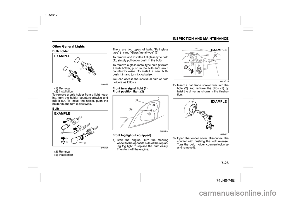
1) Start the engine. Turn the steering
wheel to the opposite side of the replac-
ing fog light to replace the bulb easily.
Then turn off the engine.
68LM715
2) Insert a flat blade screwdriver into the
hole (2) and remove the clips (1) by
twist the driver as shown in the illustra-
tion.
80JM071
3) Open the fender cover. Disconnect the
coupler with pushing the lock release.
Turn the bulb holder counterclockwise
and remove it.
(1)
(1) (2)(2)
EXAMPLE
(1)
(2) (3)
(4)
EXAMPLE
EXAMPLEEXAMPLE
Fuses: 7