Automatic lock SUZUKI SWIFT 2017 5.G Owner's Manual
[x] Cancel search | Manufacturer: SUZUKI, Model Year: 2017, Model line: SWIFT, Model: SUZUKI SWIFT 2017 5.GPages: 336, PDF Size: 6.24 MB
Page 102 of 336
3-17OPERATING YOUR VEHICLE
74LH0-74E
Overdrive off switchThe transmission is a 4-speed (3-speed
plus overdrive) automatic transmission. By
operating the overdrive off switch, the
transmission can be converted to a 3-
speed automatic transmission that will not
move to the overdrive position. To convert
the transmission to the 3-speed mode,
push in the overdrive off switch and
release it.
To return the transmission to the 4-speed
mode, push in the overdrive off switch
again.
When the ignition switch is turned to the
“ACC” position or the engine switch is
pressed to change the ignition mode to
“ACC”, the transmission in the 3-speed
mode is converted to the 4-speed mode
automatically.]
The 3-speed mode is suitable for the fol-
lowing driving conditions:
Driving on hilly, winding roads
– You can drive more smoothly with less
frequent gear changing
Going down a steep hill
– Some engine braking is provided
NOTE:
If you move the gearshift lever to a lower
gear while driving faster than the maximum
allowable speed for the lower gear, the
transaxle will not actually downshift until
your speed drops below the maximum
speed for the lower gear.
If You Cannot Shift Automatic trans-
mission Gearshift Lever Out of “P”
(PARK)Automatic transmission
Vehicles with an automatic transmission
have an electrically operated parklock fea-
ture. If the vehicle’s battery is discharged,
or there is some other electrical failure, the
automatic transmission cannot be shifted
out of Park in the normal way. Jump start-
ing may correct the condition. If not, follow
the procedure described below. This pro-
cedure will permit shifting the transmission
out of Park.
1) Be sure the parking brake is firmly
applied.
2) If the engine is running, stop the
engine.
3) Make sure the key is in the “ON” or
“ACC” position, or the ignition mode is
“ON” or “ACC”.
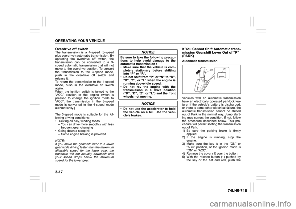
4) Remove the cover (1) over the button.
5) With the release button (1) pushed by
the key or the flat end rod, push the
NOTICE
Be sure to take the following precau-
tions to help avoid damage to the
automatic transmission :
Make sure that the vehicle is com-
pletely stationary before shifting
into “P” or “R”.
Do not shift from “P” or “N” to “R”,
“D”, “2”, or “L” when the engine is
running above idle speed.
Do not rev the engine with the
transmission in a drive position
(“R”, “D”, “2”, or “L”) and the front
wheels not moving.
NOTICE
Do not use the accelerator to hold
the vehicle on a hill. Use the vehi-
cle’s brakes.
(1)
(2)
Page 115 of 336
3-30
OPERATING YOUR VEHICLE
74LH0-74E
Anti-Lock Brake System (ABS)
(if equipped)ABS will help you avoid skidding by elec-
tronically controlling braking pressure. It
will also help you maintain steering control
when braking on slippery surfaces or when
braking hard.
The ABS works automatically, so you do
not need any special braking technique.
Just push the brake pedal down without
pumping. The ABS will operate whenever it
senses that the wheels are locking up. You
may feel the brake pedal moves a little
while the ABS is operating.
NOTE:
The ABS will not work if vehicle speed is
under about 10 km/h (6mph).
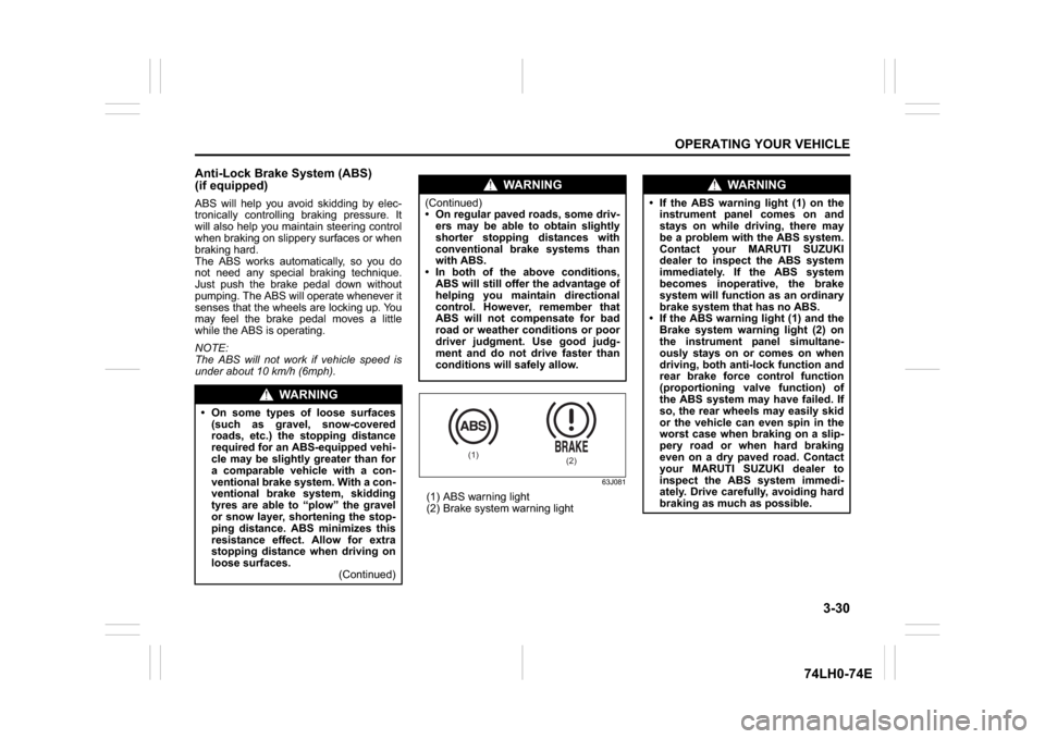
63J081
(1) ABS warning light
(2) Brake system warning light
WA R N I N G
On some types of loose surfaces
(such as gravel, snow-covered
roads, etc.) the stopping distance
required for an ABS-equipped vehi-
cle may be slightly greater than for
a comparable vehicle with a con-
ventional brake system. With a con-
ventional brake system, skidding
tyres are able to “plow” the gravel
or snow layer, shortening the stop-
ping distance. ABS minimizes this
resistance effect. Allow for extra
stopping distance when driving on
loose surfaces.
(Continued)
WA R N I N G
(Continued)
On regular paved roads, some driv-
ers may be able to obtain slightly
shorter stopping distances with
conventional brake systems than
with ABS.
In both of the above conditions,
ABS will still offer the advantage of
helping you maintain directional
control. However, remember that
ABS will not compensate for bad
road or weather conditions or poor
driver judgment. Use good judg-
ment and do not drive faster than
conditions will safely allow.
(1)
(2)
WA R N I N G
If the ABS warning light (1) on the
instrument panel comes on and
stays on while driving, there may
be a problem with the ABS system.
Contact your MARUTI SUZUKI
dealer to inspect the ABS system
immediately. If the ABS system
becomes inoperative, the brake
system will function as an ordinary
brake system that has no ABS.
If the ABS warning light (1) and the
Brake system warning light (2) on
the instrument panel simultane-
ously stays on or comes on when
driving, both anti-lock function and
rear brake force control function
(proportioning valve function) of
the ABS system may have failed. If
so, the rear wheels may easily skid
or the vehicle can even spin in the
worst case when braking on a slip-
pery road or when hard braking
even on a dry paved road. Contact
your MARUTI SUZUKI dealer to
inspect the ABS system immedi-
ately. Drive carefully, avoiding hard
braking as much as possible.
Page 136 of 336
5-9OTHER CONTROLS AND EQUIPMENT
74LH0-74E
mum performance and durability of your air
conditioner, it needs to be run periodically.
Operate the air conditioner at least once a
month for one minute with the engine
idling. This circulates the refrigerant and oil
and helps protect the internal components.
NOTE:
Your vehicle uses the air conditioning
refrigerant HFC-134a, commonly called
“R-134a”. Only R-134a should be used in
your vehicle.Radio Antenna
63J055
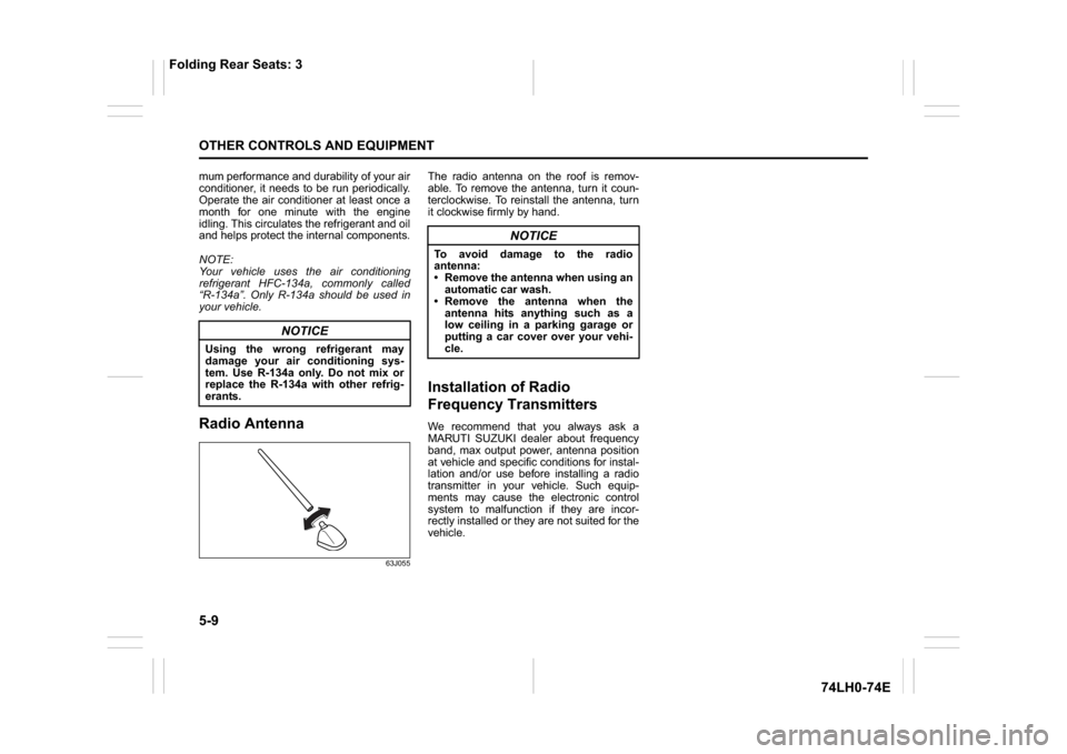
The radio antenna on the roof is remov-
able. To remove the antenna, turn it coun-
terclockwise. To reinstall the antenna, turn
it clockwise firmly by hand.Installation of Radio
Frequency TransmittersWe recommend that you always ask a
MARUTI SUZUKI dealer about frequency
band, max output power, antenna position
at vehicle and specific conditions for instal-
lation and/or use before installing a radio
transmitter in your vehicle. Such equip-
ments may cause the electronic control
system to malfunction if they are incor-
rectly installed or they are not suited for the
vehicle.
NOTICE
Using the wrong refrigerant may
damage your air conditioning sys-
tem. Use R-134a only. Do not mix or
replace the R-134a with other refrig-
erants.
NOTICE
To avoid damage to the radio
antenna:
Remove the antenna when using an
automatic car wash.
Remove the antenna when the
antenna hits anything such as a
low ceiling in a parking garage or
putting a car cover over your vehi-
cle.
Folding Rear Seats: 3
Page 143 of 336
5-16
OTHER CONTROLS AND EQUIPMENT
74LH0-74E
A CD is to be inserted with its label side
up.
When there is a CD already in the unit, it
is impossible to insert another CD with-
out ejecting the CD in the unit. Do not
use force to insert a CD into the CD
insertion slot.
Loading a CD
Insert a CD in the Insertion slot (1).
When a CD is loaded, play starts.
Ejecting a CD
Press the Eject button (2).
When the ignition mode is “LOCK”, the CD
remained ejected for around 15 seconds or
longer will automatically be drawn inside
the unit. (Auto reload function)
The backup eject function:
This function allows you to eject a CD by
pressing the Eject button (2) even when
the ignition mode is off.Listening to a CD
When a CD is inserted, playback will auto-
matically start.
When a CD is already inside the unit,
press the CD button (3) to start playback.
Selecting a track
Press the Up button (4) to listen to the
next track.
Press the Down button (5) twice to listen
to the previous track.
When the Down button (5) is pressed
once, the track currently being played
will start from the beginning again.
Fast forwarding/Rewinding a track
Hold down the Up button (4) to fast for-
ward the track.
Hold down the Down button (5) to fast
rewind the track.Random playback
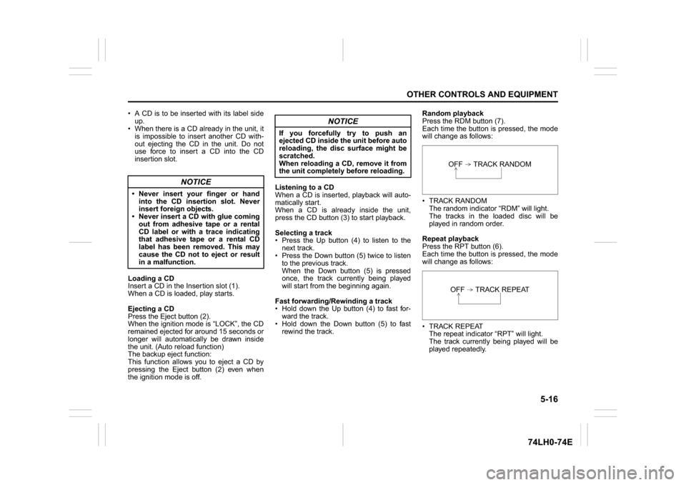
Press the RDM button (7).
Each time the button is pressed, the mode
will change as follows:
TRACK RANDOM
The random indicator “RDM” will light.
The tracks in the loaded disc will be
played in random order.
Repeat playback
Press the RPT button (6).
Each time the button is pressed, the mode
will change as follows:
TRACK REPEAT
The repeat indicator “RPT” will light.
The track currently being played will be
played repeatedly.
NOTICE
Never insert your finger or hand
into the CD insertion slot. Never
insert foreign objects.
Never insert a CD with glue coming
out from adhesive tape or a rental
CD label or with a trace indicating
that adhesive tape or a rental CD
label has been removed. This may
cause the CD not to eject or result
in a malfunction.
NOTICE
If you forcefully try to push an
ejected CD inside the unit before auto
reloading, the disc surface might be
scratched.
When reloading a CD, remove it from
the unit completely before reloading.
OFF TRACK RANDOMOFF TRACK REPEAT
Page 188 of 336

6-5VEHICLE LOADING AND TOWING
74LH0-74E
A: 2WD VEHICLES WITH MANUAL
TRANSAXLE OR AUTOMATIC
TRANSAXLE OR AUTO GEAR
SHIFT1) Secure the front wheels on a towing
dolly according to the instructions pro-
vided by the dolly manufacturer.
2) Release the parking brake.
NOTICE
The steering column is not strong
enough to withstand shocks trans-
mitted from the front wheels during
towing. Always unlock the steering
wheel before towing. TOWING METHOD AFROM THE FRONT:
FRONT WHEELS ON A DOLLY
AND REAR WHEELS ON THE GROUND
B: 2WD VEHICLES WITH MANUAL TRANSAXLE OR AUTO GEAR SHIFT1) Shift the manual transaxle lever into neutral.
2) Turn the ignition key to the “ACC” position or change the ignition mode to the “ACC” to
unlock the steering wheel.
3) Release the parking brake.
ACC
N
TOWING METHOD BFROM THE FRONT:
FRONT WHEELS ON THE GROUND
Page 192 of 336
7-1INSPECTION AND MAINTENANCE
74LH0-74E
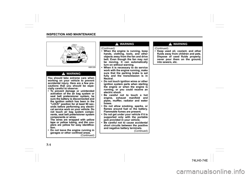
60B128S
WA R N I N G
You should take extreme care when
working on your vehicle to prevent
accidental injury. Here are a few pre-
cautions that you should be espe-
cially careful to observe:
To prevent damage or unintended
activation of the air bag system or
seat belt pretensioner system, be
sure the battery is disconnected and
the ignition switch has been in the
“LOCK” position for at least 90 sec-
onds before performing any electri-
cal service work on your vehicle. Do
not touch air bag system compo-
nents, seat belt pretensioner system
components or wires.
The wires are wrapped with yellow
tape or yellow tubing, and the cou-
plers are yellow for easy identifica-
tion.
Do not leave the engine running in
garages or other confined areas.
(Continued)
WA R N I N G
(Continued)
When the engine is running, keep
hands, clothing, tools, and other
objects away from the fan and drive
belt. Even though the fan may not
be moving, it can automatically
turn on without warning.
When it is necessary to do service
work with the engine running, make
sure that the parking brake is set
fully and the transmission is in
Neutral.
Do not touch ignition wires or other
ignition system parts when starting
the engine or when the engine is
running, or you could receive an
electric shock.
Be careful not to touch a hot
engine, exhaust manifold and
pipes, muffler, radiator and water
hoses.
Do not allow smoking, sparks, or
flames around fuel or the battery.
Flammable fumes are present.
Do not get under your vehicle if it is
supported only with the portable
jack provided in your vehicle.
Be careful not to cause accidental
short circuits between the positive
and negative battery terminals.
(Continued)
WA R N I N G
(Continued)
Keep used oil, coolant, and other
fluids away from children and pets.
Dispose of used fluids properly;
never pour them on the ground,
into sewers, etc.
Page 200 of 336
7-9INSPECTION AND MAINTENANCE
74LH0-74E
Replace the Oil Filter(For Petrol Engine Model)
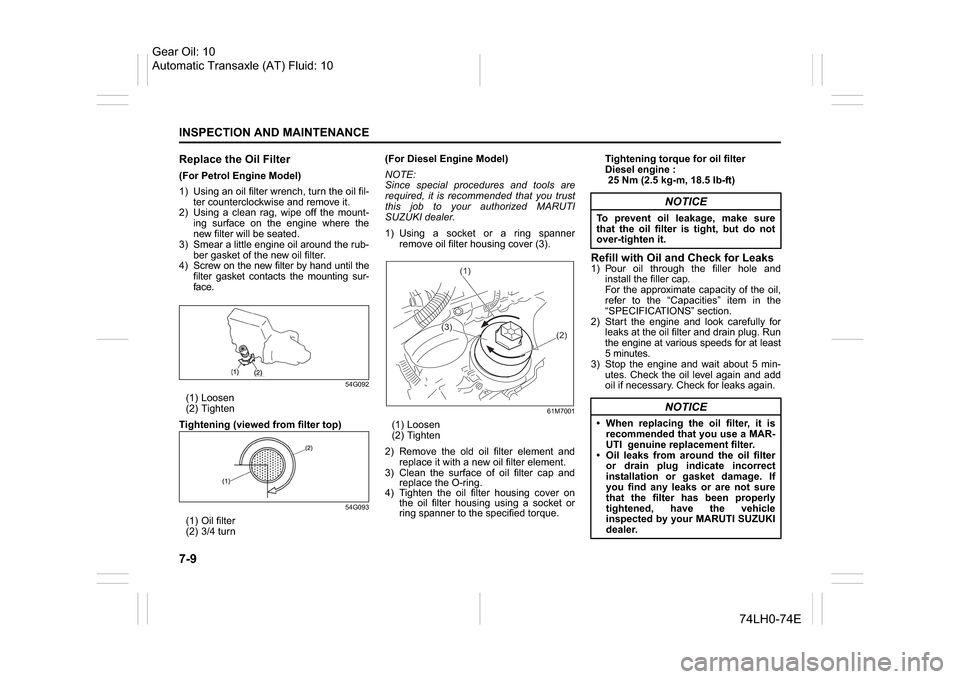
1) Using an oil filter wrench, turn the oil fil-
ter counterclockwise and remove it.
2) Using a clean rag, wipe off the mount-
ing surface on the engine where the
new filter will be seated.
3) Smear a little engine oil around the rub-
ber gasket of the new oil filter.
4) Screw on the new filter by hand until the
filter gasket contacts the mounting sur-
face.
54G092
(1) Loosen
(2) Tighten
Tightening (viewed from filter top)
54G093
(1) Oil filter
(2) 3/4 turn(For Diesel Engine Model)
NOTE:
Since special procedures and tools are
required, it is recommended that you trust
this job to your authorized MARUTI
SUZUKI dealer.
1) Using a socket or a ring spanner
remove oil filter housing cover (3).
61M7001
(1) Loosen
(2) Tighten
2) Remove the old oil filter element and
replace it with a new oil filter element.
3) Clean the surface of oil filter cap and
replace the O-ring.
4) Tighten the oil filter housing cover on
the oil filter housing using a socket or
ring spanner to the specified torque.Tightening torque for oil filter
Diesel engine :
25 Nm (2.5 kg-m, 18.5 lb-ft)
Refill with Oil and Check for Leaks1) Pour oil through the filler hole and
install the filler cap.
For the approximate capacity of the oil,
refer to the “Capacities” item in the
“SPECIFICATIONS” section.
2) Start the engine and look carefully for
leaks at the oil filter and drain plug. Run
the engine at various speeds for at least
5 minutes.
3) Stop the engine and wait about 5 min-
utes. Check the oil level again and add
oil if necessary. Check for leaks again.
(1)
(3)
(2)
NOTICE
To prevent oil leakage, make sure
that the oil filter is tight, but do not
over-tighten it.
NOTICE
When replacing the oil filter, it is
recommended that you use a MAR-
UTI genuine replacement filter.
Oil leaks from around the oil filter
or drain plug indicate incorrect
installation or gasket damage. If
you find any leaks or are not sure
that the filter has been properly
tightened, have the vehicle
inspected by your MARUTI SUZUKI
dealer.
Gear Oil: 10
Automatic Transaxle (AT) Fluid: 10
Page 202 of 336
7-11INSPECTION AND MAINTENANCE
74LH0-74E
reaches the “FULL” mark. Never fill the res-
ervoir tank above the “FULL” mark.
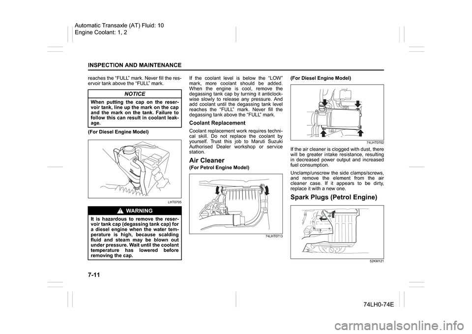
(For Diesel Engine Model)
LHT0705
If the coolant level is below the “LOW”
mark, more coolant should be added.
When the engine is cool, remove the
degassing tank cap by turning it anticlock-
wise slowly to release any pressure. And
add coolant until the degassing tank level
reaches the “FULL” mark. Never fill the
degassing tank above the “FULL” mark.Coolant ReplacementCoolant replacement work requires techni-
cal skill. Do not replace the coolant by
yourself. Trust this job to Maruti Suzuki
Authorised Dealer workshop or service
station.Air Cleaner(For Petrol Engine Model)
74LHT0713
(For Diesel Engine Model)
74LHT0702
If the air cleaner is clogged with dust, there
will be greater intake resistance, resulting
in decreased power output and increased
fuel consumption.
Unclamp/unscrew the side clamps/screws,
and remove the element from the air
cleaner case. If it appears to be dirty,
replace it with a new one.Spark Plugs (Petrol Engine)
52KM121
NOTICE
When putting the cap on the reser-
voir tank, line up the mark on the cap
and the mark on the tank. Failure to
follow this can result in coolant leak-
age.
WA R N I N G
It is hazardous to remove the reser-
voir tank cap (degassing tank cap) for
a diesel engine when the water tem-
perature is high, because scalding
fluid and steam may be blown out
under pressure. Wait until the coolant
temperature has lowered before
removing the cap.
Automatic Transaxle (AT) Fluid: 10
Engine Coolant: 1, 2
Page 231 of 336
8-8
EMERGENCY SERVICE
74LH0-74E
For Diesel
65D350D
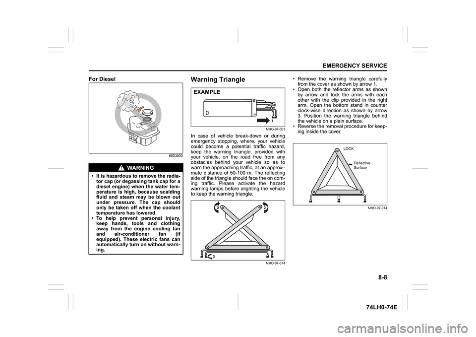
Warning Triangle
MHO-07-001
In case of vehicle break-down or during
emergency stopping, where, your vehicle
could become a potential traffic hazard,
keep the warning triangle, provided with
your vehicle, on the road free from any
obstacles behind your vehicle so as to
warn the approaching traffic, at an approxi-
mate distance of 50-100 m. The reflecting
side of the triangle should face the on com-
ing traffic. Please activate the hazard
warning lamps before alighting the vehicle
to keep the warning triangle.
MHO-07-014
Remove the warning triangle carefully
from the cover as shown by arrow 1.
Open both the reflector arms as shown
by arrow and lock the arms with each
other with the clip provided in the right
arm. Open the bottom stand in counter
clock-wise direction as shown by arrow
3. Position the warning triangle behind
the vehicle on a plain surface.
Reverse the removal procedure for keep-
ing inside the cover.
MHO-07-014
WA R N I N G
It is hazardous to remove the radia-
tor cap (or degassing tank cap for a
diesel engine) when the water tem-
perature is high, because scalding
fluid and steam may be blown out
under pressure. The cap should
only be taken off when the coolant
temperature has lowered.
To help prevent personal injury,
keep hands, tools and clothing
away from the engine cooling fan
and air-conditioner fan (if
equipped). These electric fans can
automatically turn on without warn-
ing.
EXAMPLE