Proper SUZUKI SWIFT 2017 5.G Owner's Guide
[x] Cancel search | Manufacturer: SUZUKI, Model Year: 2017, Model line: SWIFT, Model: SUZUKI SWIFT 2017 5.GPages: 336, PDF Size: 6.24 MB
Page 151 of 336
5-24
OTHER CONTROLS AND EQUIPMENT
74LH0-74E
NOTE:
Please consult your place of purchase
for details about whether a given auxil-
iary audio source can be connected and
the proper auxiliary cord to use.
The volume and tone controls of the
auxiliary audio source can be adjusted
on the unit.
In AUX mode, the volume setting is dif-
ferent from another mode.
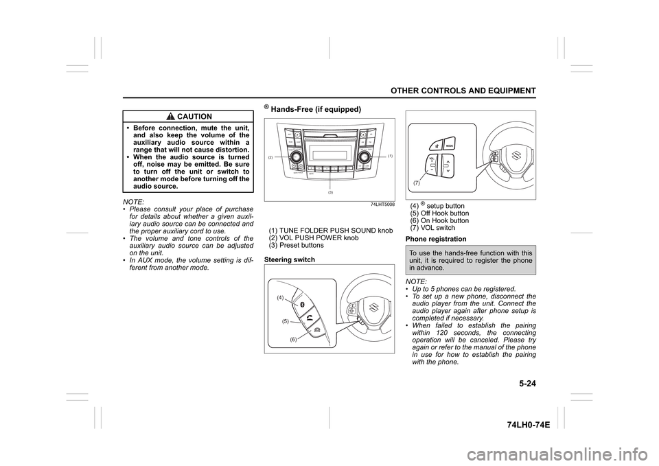
® Hands-Free (if equipped)
74LHT5008
(1) TUNE FOLDER PUSH SOUND knob
(2) VOL PUSH POWER knob
(3) Preset buttons
Steering switch(4)
® setup button
(5) Off Hook button
(6) On Hook button
(7) VOL switch
Phone registration
NOTE:
Up to 5 phones can be registered.
To set up a new phone, disconnect the
audio player from the unit. Connect the
audio player again after phone setup is
completed if necessary.
When failed to establish the pairing
within 120 seconds, the connecting
operation will be canceled. Please try
again or refer to the manual of the phone
in use for how to establish the pairing
with the phone.
CAUTION
Before connection, mute the unit,
and also keep the volume of the
auxiliary audio source within a
range that will not cause distortion.
When the audio source is turned
off, noise may be emitted. Be sure
to turn off the unit or switch to
another mode before turning off the
audio source.
(2)
B S U
CD
2
3 4 5 6
SEEK/TRACK
AS
AMFM RPT
RDM
DISP
PUSHSOUND
TUNE/FLD
VOLPWRPUSH
11
MENU
(3)
(1)
(4)(5)
(6)
(7)To use the hands-free function with this
unit, it is required to register the phone
in advance.
Page 174 of 336
5-47OTHER CONTROLS AND EQUIPMENT
74LH0-74E
Fuel Filler CapSwift
68LM522
Dzire
74LHT0511
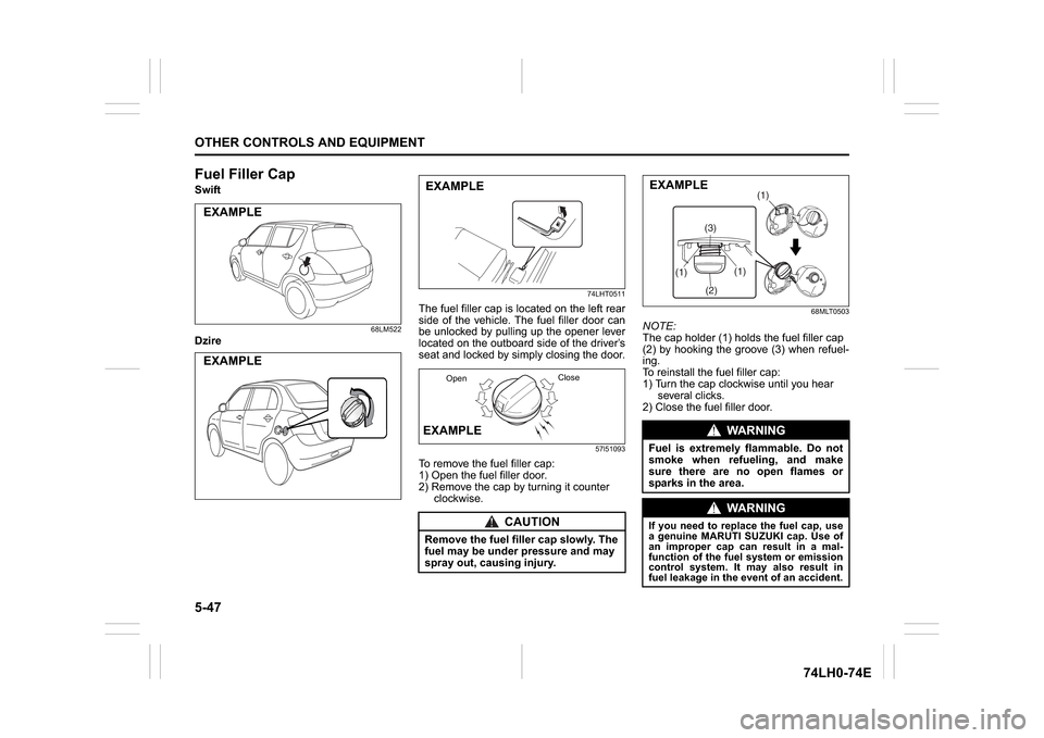
The fuel filler cap is located on the left rear
side of the vehicle. The fuel filler door can
be unlocked by pulling up the opener lever
located on the outboard side of the driver’s
seat and locked by simply closing the door.
57l51093
To remove the fuel filler cap:
1) Open the fuel filler door.
2) Remove the cap by turning it counter
clockwise.
68MLT0503
NOTE:
The cap holder (1) holds the fuel filler cap
(2) by hooking the groove (3) when refuel-
ing.
To reinstall the fuel filler cap:
1) Turn the cap clockwise until you hear
several clicks.
2) Close the fuel filler door.
EXAMPLEEXAMPLE
CAUTION
Remove the fuel filler cap slowly. The
fuel may be under pressure and may
spray out, causing injury.EXAMPLEEXAMPLE
OpenClose
WA R N I N G
Fuel is extremely flammable. Do not
smoke when refueling, and make
sure there are no open flames or
sparks in the area.
WA R N I N G
If you need to replace the fuel cap, use
a genuine MARUTI SUZUKI cap. Use of
an improper cap can result in a mal-
function of the fuel system or emission
control system. It may also result in
fuel leakage in the event of an accident.
(1)
(2)(3)(1)
(1)
EXAMPLE
Page 179 of 336
5-52
OTHER CONTROLS AND EQUIPMENT
74LH0-74E
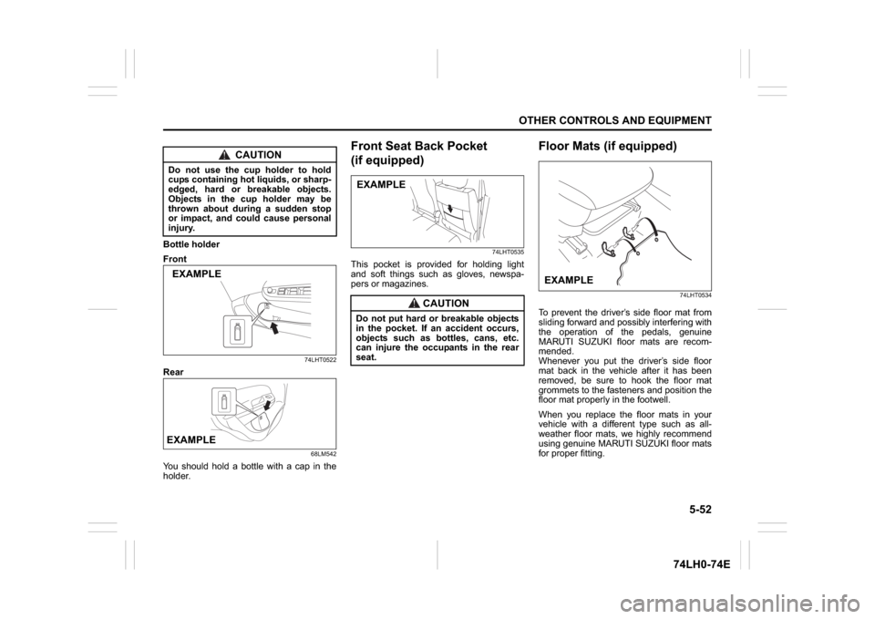
Bottle holder
Front
74LHT0522
Rear
68LM542
You should hold a bottle with a cap in the
holder.
Front Seat Back Pocket
(if equipped)
74LHT0535
This pocket is provided for holding light
and soft things such as gloves, newspa-
pers or magazines.
Floor Mats (if equipped)
74LHT0534
To prevent the driver’s side floor mat from
sliding forward and possibly interfering with
the operation of the pedals, genuine
MARUTI SUZUKI floor mats are recom-
mended.
Whenever you put the driver’s side floor
mat back in the vehicle after it has been
removed, be sure to hook the floor mat
grommets to the fasteners and position the
floor mat properly in the footwell.
When you replace the floor mats in your
vehicle with a different type such as all-
weather floor mats, we highly recommend
using genuine MARUTI SUZUKI floor mats
for proper fitting.
CAUTION
Do not use the cup holder to hold
cups containing hot liquids, or sharp-
edged, hard or breakable objects.
Objects in the cup holder may be
thrown about during a sudden stop
or impact, and could cause personal
injury.EXAMPLEEXAMPLE
CAUTION
Do not put hard or breakable objects
in the pocket. If an accident occurs,
objects such as bottles, cans, etc.
can injure the occupants in the rear
seat.EXAMPLE
EXAMPLE
Page 185 of 336
6-2
VEHICLE LOADING AND TOWING
74LH0-74E
Brakes
Ty r e s
MirrorsCheck to see if your vehicle’s mirrors meet
local requirements for mirrors used on
towing vehicles. If they do not, you must
install the required mirrors before you tow.
Vehicle/Trailer LoadingTo load your vehicle and trailer properly,
you must know how to measure gross
trailer weight and trailer nose weight.
Gross Trailer Weight is the weight of the
trailer plus all the cargo in it. You can mea-
sure gross trailer weight by putting the fully
loaded trailer on a vehicle scale.
Nose Weight is the downward force
exerted on the tow bar by the trailer cou-
pler, with the trailer fully loaded and the
coupler at its normal towing height. This
weight can be measured using a bathroom
scales.
The weight of your loaded trailer (Gross
Trailer Weight) should never exceed the
“Towing capacity”.
Distribute cargo in your trailer so that nose
weight is about 10% of gross trailer weight,
but does not exceed “Maximum vertical
load on trailer hitch point”. You should
measure gross trailer weight and nose
weight before towing to make sure that
your load is properly distributed.
WA R N I N G
If trailer brakes are used, you should
follow all instructions provided by
the manufacturer. Never connect to
the brake system of your vehicle and
never take an electrical supply
directly from the wiring harness.
WA R N I N G
When towing a trailer, it is very
important for your vehicle and trailer
to have properly inflated tyres. Your
vehicle’s tyres should be inflated to
the pressures listed on your vehicles
Tyre Information label. If laden pres-
sures are listed on the label, the tyres
should be inflated to the laden pres-
sures. Inflate trailer tyres according
to the specifications provided by the
trailer manufacturer.
WA R N I N G
Improper weight distribution of your
trailer may result in poor vehicle han-
dling and swaying of the trailer.
Always make sure that trailer nose
weight is about 10% of gross trailer
weight, but does not exceed “Maxi-
mum vertical load on trailer hitch
point”. Also make sure that the cargo
is properly secured. Failure to
observe this requirement may result
in an accident.
WA R N I N G
Never overload your trailer or your
vehicle. Gross trailer weight must
never exceed the “Towing capacity”.
Gross vehicle weight (sum of the
weights of the vehicle, all the occu-
pants, accessories including tow
bars and a trailer hitch, cargo and
trailer nose weight) must never
exceed the Gross Vehicle Weight Rat-
ing (GVWR) listed in the “SPECIFICA-
TIONS” section.
Page 187 of 336
6-4
VEHICLE LOADING AND TOWING
74LH0-74E
60A186
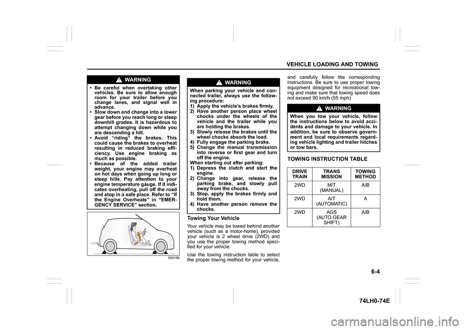
Towing Your VehicleYour vehicle may be towed behind another
vehicle (such as a motor-home), provided
your vehicle is 2 wheel drive (2WD) and
you use the proper towing method speci-
fied for your vehicle.
Use the towing instruction table to select
the proper towing method for your vehicle,and carefully follow the corresponding
instructions. Be sure to use proper towing
equipment designed for recreational tow-
ing and make sure that towing speed does
not exceed 90 km/h (55 mph)
TOWING INSTRUCTION TABLE
WA R N I N G
Be careful when overtaking other
vehicles. Be sure to allow enough
room for your trailer before you
change lanes, and signal well in
advance. Slow down and change into a lower
gear before you reach long or steep
downhill grades. It is hazardous to
attempt changing down while you
are descending a hill.
Avoid “riding” the brakes. This
could cause the brakes to overheat
resulting in reduced braking effi-
ciency. Use engine braking as
much as possible.
Because of the added trailer
weight, your engine may overheat
on hot days when going up long or
steep hills. Pay attention to your
engine temperature gauge. If it indi-
cates overheating, pull off the road
and stop in a safe place. Refer to “If
the Engine Overheats” in “EMER-
GENCY SERVICE” section.
WA R N I N G
When parking your vehicle and con-
nected trailer, always use the follow-
ing procedure:
1) Apply the vehicle’s brakes firmly.
2) Have another person place wheel
chocks under the wheels of the
vehicle and the trailer while you
are holding the brakes.
3) Slowly release the brakes until the
wheel chocks absorb the load.
4) Fully engage the parking brake.
5) Change the manual transmission
into reverse or first gear and turn
off the engine.
When starting out after parking:
1) Depress the clutch and start the
engine.
2) Change into gear, release the
parking brake, and slowly pull
away from the chocks.
3) Stop, apply the brakes firmly and
hold them.
4) Have another person remove the
chocks.
WA R N I N G
When you tow your vehicle, follow
the instructions below to avoid acci-
dents and damage to your vehicle. In
addition, be sure to observe govern-
ment and local requirements regard-
ing vehicle lighting and trailer hitches
or tow bars.
DRIVE
TRAINTRANS
MISSIONTOWING
METHOD
2WD M/T
(MANUAL)A/B
2WD A/T
(AUTOMATIC)A
2WD AGS
(AUTO GEAR
SHIFT)A/B
Page 192 of 336
7-1INSPECTION AND MAINTENANCE
74LH0-74E
60B128S
WA R N I N G
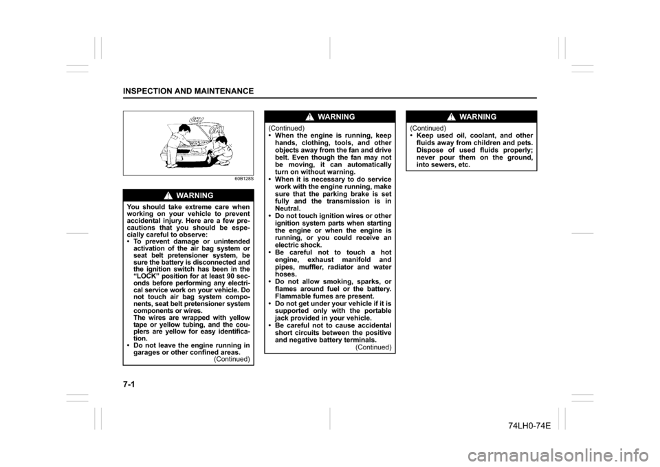
You should take extreme care when
working on your vehicle to prevent
accidental injury. Here are a few pre-
cautions that you should be espe-
cially careful to observe:
To prevent damage or unintended
activation of the air bag system or
seat belt pretensioner system, be
sure the battery is disconnected and
the ignition switch has been in the
“LOCK” position for at least 90 sec-
onds before performing any electri-
cal service work on your vehicle. Do
not touch air bag system compo-
nents, seat belt pretensioner system
components or wires.
The wires are wrapped with yellow
tape or yellow tubing, and the cou-
plers are yellow for easy identifica-
tion.
Do not leave the engine running in
garages or other confined areas.
(Continued)
WA R N I N G
(Continued)
When the engine is running, keep
hands, clothing, tools, and other
objects away from the fan and drive
belt. Even though the fan may not
be moving, it can automatically
turn on without warning.
When it is necessary to do service
work with the engine running, make
sure that the parking brake is set
fully and the transmission is in
Neutral.
Do not touch ignition wires or other
ignition system parts when starting
the engine or when the engine is
running, or you could receive an
electric shock.
Be careful not to touch a hot
engine, exhaust manifold and
pipes, muffler, radiator and water
hoses.
Do not allow smoking, sparks, or
flames around fuel or the battery.
Flammable fumes are present.
Do not get under your vehicle if it is
supported only with the portable
jack provided in your vehicle.
Be careful not to cause accidental
short circuits between the positive
and negative battery terminals.
(Continued)
WA R N I N G
(Continued)
Keep used oil, coolant, and other
fluids away from children and pets.
Dispose of used fluids properly;
never pour them on the ground,
into sewers, etc.
Page 198 of 336
7-7INSPECTION AND MAINTENANCE
74LH0-74E
(1) Preferred
Be sure that the engine oil you use comes
under the quality classification of ACEA
A5/B5. The recommended Engine oil is
5W30 A5/B5. Oil Level Check(For Petrol Engine Model)
80G064
52D084
(For Diesel Engine Model)
84E012
(1) MIN
(2) MAX
(3) Engine oil dipstick
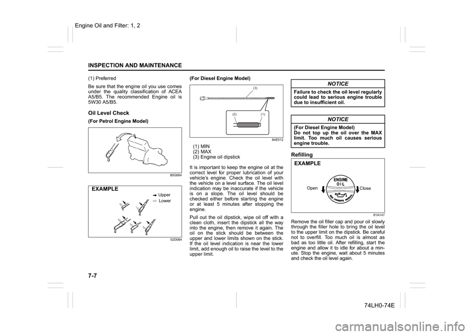
It is important to keep the engine oil at the
correct level for proper lubrication of your
vehicle’s engine. Check the oil level with
the vehicle on a level surface. The oil level
indication may be inaccurate if the vehicle
is on a slope. The oil level should be
checked either before starting the engine
or at least 5 minutes after stopping the
engine.
Pull out the oil dipstick, wipe oil off with a
clean cloth, insert the dipstick all the way
into the engine, then remove it again. The
oil on the stick should be between the
upper and lower limits shown on the stick.
If the oil level indication is near the lower
limit, add enough oil to raise the level to the
upper limit.
Refilling
81A147
Remove the oil filler cap and pour oil slowly
through the filler hole to bring the oil level
to the upper limit on the dipstick. Be careful
not to overfill. Too much oil is almost as
bad as too little oil. After refilling, start the
engine and allow it to idle for about a min-
ute. Stop the engine, wait about 5 minutes
and check the oil level again.
Upper
Lower
EXAMPLE
(3)
(2) (1)
NOTICE
Failure to check the oil level regularly
could lead to serious engine trouble
due to insufficient oil.
NOTICE
(For Diesel Engine Model)
Do not top up the oil over the MAX
limit. Too much oil causes serious
engine trouble.
Close Open
EXAMPLE
Engine Oil and Filter: 1, 2
Page 199 of 336

7-8
INSPECTION AND MAINTENANCE
74LH0-74E
Changing Engine Oil and FilterDrain the engine oil while the engine is still
warm.
56KN054
1) Remove the oil filler cap.
2) Place a drain pan under the drain plug.
3) Using a wrench, remove the drain plug
and drain out the engine oil.
60G306
Tightening torque for drain plug
Petrol engine:
35 Nm (3.5 kg-m, 25.3 lb-ft)
For Diesel Engine
60G306
For Diesel Engine
20 Nm (2.0 kg-m, 14.5 Ib-ft)4) Reinstall the drain plug and new gasket
(1). Tighten the plug with a wrench to
the specified torque.
CAUTION
The engine oil temperature may be
high enough to burn your fingers
when the drain plug is loosened. Wait
until the drain plug is cool enough to
touch with your bare hands.
Open Close
EXAMPLE
EXAMPLEEXAMPLE
WA R N I N G
New and used oil can be hazardous.
Children and pets may be harmed by
swallowing new or used oil. Keep
new and used oil and used oil filters
away from children and pets.
Continuous contact with used engine
oil may cause skin cancer laboratory
animals
Brief contact with used oil may irri-
tate skin.
To minimize your exposure to used
oil, wear a long-sleeve shirt and
moisture-proof gloves (such as
diswashing gloves) when changing
oil. If oil contacts your skin, wash
thoroughly with soap and water.
Launder any clothing or rags if wet
with oil.
Recycle or properly dispose of used
oil and filters.
Gear Oil: 10
Page 200 of 336
7-9INSPECTION AND MAINTENANCE
74LH0-74E
Replace the Oil Filter(For Petrol Engine Model)
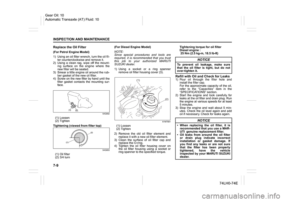
1) Using an oil filter wrench, turn the oil fil-
ter counterclockwise and remove it.
2) Using a clean rag, wipe off the mount-
ing surface on the engine where the
new filter will be seated.
3) Smear a little engine oil around the rub-
ber gasket of the new oil filter.
4) Screw on the new filter by hand until the
filter gasket contacts the mounting sur-
face.
54G092
(1) Loosen
(2) Tighten
Tightening (viewed from filter top)
54G093
(1) Oil filter
(2) 3/4 turn(For Diesel Engine Model)
NOTE:
Since special procedures and tools are
required, it is recommended that you trust
this job to your authorized MARUTI
SUZUKI dealer.
1) Using a socket or a ring spanner
remove oil filter housing cover (3).
61M7001
(1) Loosen
(2) Tighten
2) Remove the old oil filter element and
replace it with a new oil filter element.
3) Clean the surface of oil filter cap and
replace the O-ring.
4) Tighten the oil filter housing cover on
the oil filter housing using a socket or
ring spanner to the specified torque.Tightening torque for oil filter
Diesel engine :
25 Nm (2.5 kg-m, 18.5 lb-ft)
Refill with Oil and Check for Leaks1) Pour oil through the filler hole and
install the filler cap.
For the approximate capacity of the oil,
refer to the “Capacities” item in the
“SPECIFICATIONS” section.
2) Start the engine and look carefully for
leaks at the oil filter and drain plug. Run
the engine at various speeds for at least
5 minutes.
3) Stop the engine and wait about 5 min-
utes. Check the oil level again and add
oil if necessary. Check for leaks again.
(1)
(3)
(2)
NOTICE
To prevent oil leakage, make sure
that the oil filter is tight, but do not
over-tighten it.
NOTICE
When replacing the oil filter, it is
recommended that you use a MAR-
UTI genuine replacement filter.
Oil leaks from around the oil filter
or drain plug indicate incorrect
installation or gasket damage. If
you find any leaks or are not sure
that the filter has been properly
tightened, have the vehicle
inspected by your MARUTI SUZUKI
dealer.
Gear Oil: 10
Automatic Transaxle (AT) Fluid: 10
Page 201 of 336
7-10
INSPECTION AND MAINTENANCE
74LH0-74E
Engine CoolantSelection of CoolantTo maintain optimum performance and
durability of your engine, use MARUTI
SUZUKI Genuine Coolant or equivalent.
This type of coolant is best for your cooling
system as it:
Helps maintain proper engine tempera-
ture.
Gives proper protection against freezing
and boiling.
Gives proper protection against corro-
sion and rust.
Failure to use the proper coolant can dam-
age your cooling system. Your authorized
MARUTI SUZUKI dealer can help you
select the proper coolant.
Coolant Level CheckCheck the coolant level at the reservoir
tank, not at the radiator. With the engine
cool, the coolant level should be between
the “FULL” and “LOW” marks.Adding Coolant
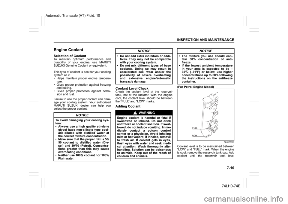
(For Petrol Engine Model)
74LHT7003
Coolant level is to be maintained between
“LOW” and “FULL” mark. When the engine
is cool, remove the reservoir tank cap. Add
coolant until the reservoir tank level
NOTICE
To avoid damaging your cooling sys-
tem:
Always use a high quality ethylene
glycol base non-silicate type cool-
ant diluted with distilled water at
the correct mixture concentration.
Make sure that the proper mix is 50/
50 coolant to distilled water (Die-
sel) and 30/70 (Petrol). Concentra-
tions greater than this may cause
overheating conditions.
Neither use 100% coolant nor 100%
Plain water.
NOTICE
Do not add extra inhibitors or addi-
tives. They may not be compatible
with your cooling system.
Do not mix different types of base
coolants. Doing so may result in
accelerated seal wear and/or the
possibility of severe overheating
and extensive engine/automatic
transaxle damage.
WA R N I N G
Engine coolant is harmful or fatal if
swallowed or inhaled. Do not drink
antifreeze or coolant solution. If swal-
lowed, do not induce vomiting. Imme-
diately contact a poison control
center or a physician. Avoid inhaling
mist or hot vapors; if inhaled, remove
to fresh air. If coolant gets in eyes,
flush eyes with water and seek medi-
cal attention. Wash thoroughly after
handling. Solution can be poisonous
to animals. Keep out of the reach of
children and animals.
NOTICE
The mixture you use should con-
tain 50% concentration of anti-
freeze.
If the lowest ambient temperature
in your area is expected to be –
35°C (–31°F) or below, use higher
concentrations up to 60% following
the instructions on the antifreeze
container.
FULLLOWFULLLOW
Automatic Transaxle (AT) Fluid: 10