steering SUZUKI SWIFT 2017 5.G Owner's Guide
[x] Cancel search | Manufacturer: SUZUKI, Model Year: 2017, Model line: SWIFT, Model: SUZUKI SWIFT 2017 5.GPages: 336, PDF Size: 6.24 MB
Page 213 of 336

7-22
INSPECTION AND MAINTENANCE
74LH0-74E
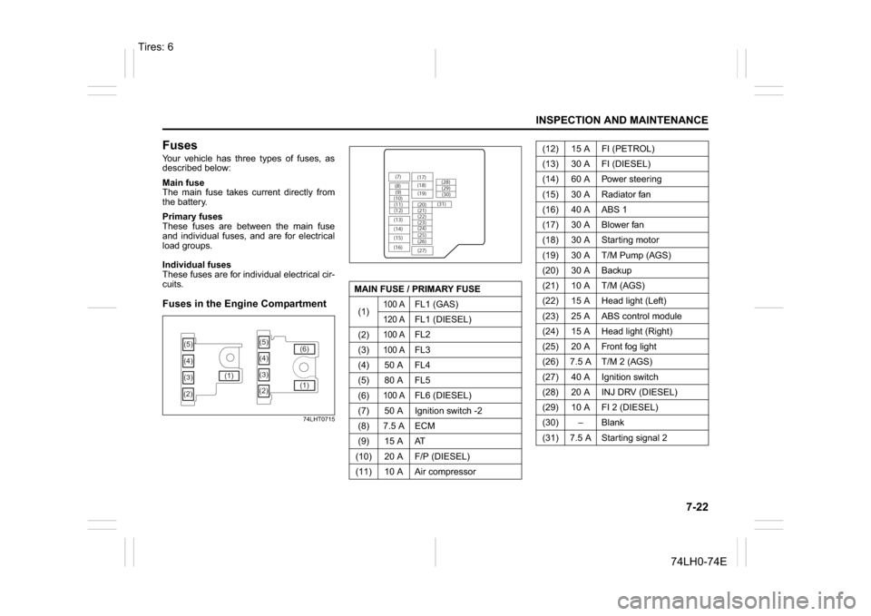
FusesYour vehicle has three types of fuses, as
described below:
Main fuse
The main fuse takes current directly from
the battery.
Primary fuses
These fuses are between the main fuse
and individual fuses, and are for electrical
load groups.
Individual fuses
These fuses are for individual electrical cir-
cuits.Fuses in the Engine Compartment
74LHT0715
(5)
(3) (4)
(2)(1)(5)
(4)
(3)
(2)(1) (6)
MAIN FUSE / PRIMARY FUSE
(1)
100 A
FL1 (GAS)
120 A
FL1 (DIESEL)
(2)
100 A
FL2
(3)
100 A
FL3
(4) 50 A FL4
(5) 80 A FL5
(6)
100 A
FL6 (DIESEL)
(7) 50 A Ignition switch -2
(8) 7.5 A ECM
(9) 15 A AT
(10) 20 A F/P (DIESEL)
(11) 10 A Air compressor
(7)
(8)(9)
(10)
(11)
(12)
(13)
(14)
(15)
(16)(17)
(18)
(20) (19)
(21)
(22)
(23)
(25) (24)
(26)
(27)(28)
(29)
(30)
(31)
(12) 15 A FI (PETROL)
(13) 30 A FI (DIESEL)
(14) 60 A Power steering
(15) 30 A Radiator fan
(16) 40 A ABS 1
(17) 30 A Blower fan
(18) 30 A Starting motor
(19) 30 A T/M Pump (AGS)
(20) 30 A Backup
(21) 10 A T/M (AGS)
(22) 15 A Head light (Left)
(23) 25 A ABS control module
(24) 15 A Head light (Right)
(25) 20 A Front fog light
(26) 7.5 A T/M 2 (AGS)
(27) 40 A Ignition switch
(28) 20 A INJ DRV (DIESEL)
(29) 10 A FI 2 (DIESEL)
(30)
Page 214 of 336

7-23INSPECTION AND MAINTENANCE
74LH0-74E
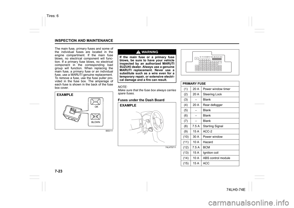
The main fuse, primary fuses and some of
the individual fuses are located in the
engine compartment. If the main fuse
blows, no electrical component will func-
tion. If a primary fuse blows, no electrical
component in the corresponding load
group will function. When replacing the
main fuse, a primary fuse or an individual
fuse, use a MARUTI genuine replacement.
To remove a fuse, use the fuse puller pro-
vided in the fuse box. The amperage of
each fuse is shown in the back of the fuse
box cover.
60G111
NOTE:
Make sure that the fuse box always carries
spare fuses.Fuses under the Dash Board
74LHT0711
EXAMPLE
BLOWNOK
WA R N I N G
If the main fuse or a primary fuse
blows, be sure to have your vehicle
inspected by an authorized MARUTI
SUZUKI dealer. Always use a genuine
MARUTI replacement. Never use a
substitute such as a wire even for a
temporary repair, or extensive electri-
cal damage and a fire can result.EXAMPLE
PRIMARY FUSE
(1) 20 A Power window timer
(2) 20 A Steering Lock
(3) – Blank
(4) 20 A Rear defogger
(5) – Blank
(6) – Blank
(7) – Blank
(8) 7.5 A Starting Signal
(9) 15 A ACC-2
(10) 30 A Power window
(11) 10 A Hazard
(12) 7.5 A BCM
(13) 15 A Ignition coil
(14) 10 A ABS control module
(15) 15 A ACC
(3)
(12)(10)
(13)
(36) (1) (2) (4)
(5)(6)
(7) (8)(9)
(11) (14) (15)
(16) (17) (18) (19) (20) (21) (22)
(23) (24) (25) (26) (27) (28) (29)
(30) (31) (32) (33) (34) (35)
Tires: 6
Page 217 of 336

7-26
INSPECTION AND MAINTENANCE
74LH0-74E
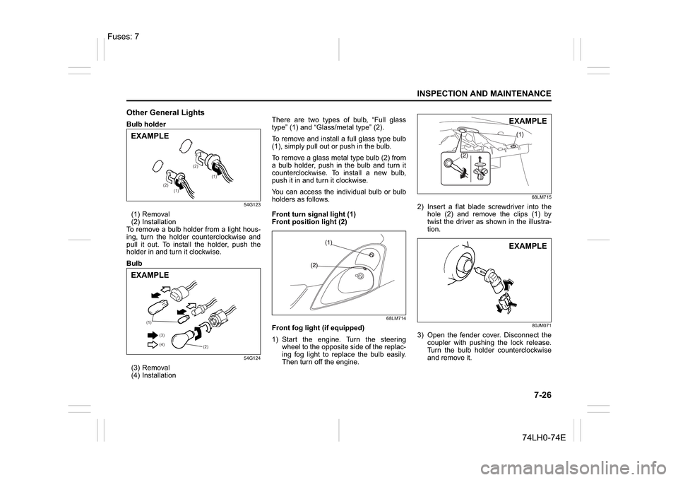
Other General LightsBulb holder
54G123
(1) Removal
(2) Installation
To remove a bulb holder from a light hous-
ing, turn the holder counterclockwise and
pull it out. To install the holder, push the
holder in and turn it clockwise.
Bulb
54G124
(3) Removal
(4) InstallationThere are two types of bulb, “Full glass
type” (1) and “Glass/metal type” (2).
To remove and install a full glass type bulb
(1), simply pull out or push in the bulb.
To remove a glass metal type bulb (2) from
a bulb holder, push in the bulb and turn it
counterclockwise. To install a new bulb,
push it in and turn it clockwise.
You can access the individual bulb or bulb
holders as follows.
Front turn signal light (1)
Front position light (2)
68LM714
Front fog light (if equipped)
1) Start the engine. Turn the steering
wheel to the opposite side of the replac-
ing fog light to replace the bulb easily.
Then turn off the engine.
68LM715
2) Insert a flat blade screwdriver into the
hole (2) and remove the clips (1) by
twist the driver as shown in the illustra-
tion.
80JM071
3) Open the fender cover. Disconnect the
coupler with pushing the lock release.
Turn the bulb holder counterclockwise
and remove it.
(1)
(1) (2)(2)
EXAMPLE
(1)
(2) (3)
(4)
EXAMPLE
EXAMPLEEXAMPLE
Fuses: 7
Page 247 of 336

11-5
SPECIFICATIONS
74LH0-74E
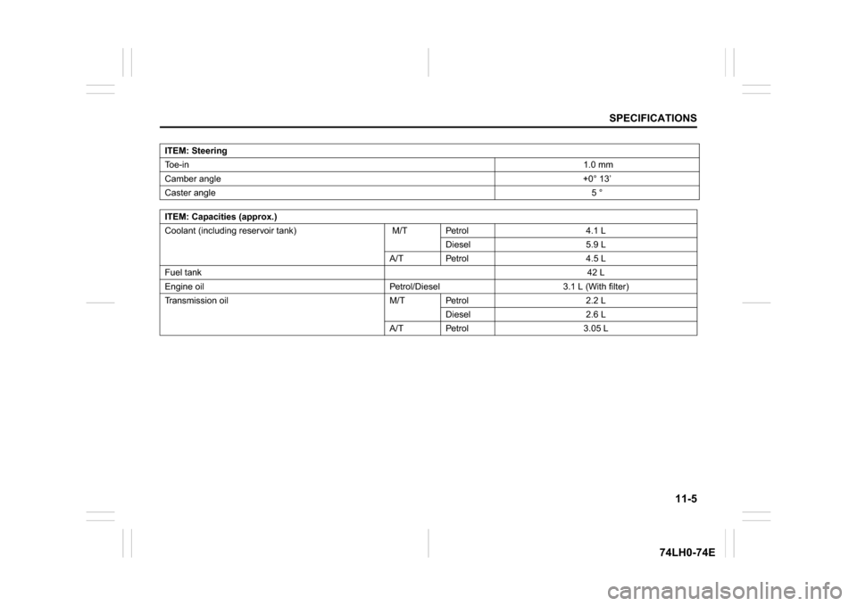
ITEM: Steering
To e - i n 1.0 mm
Camber angle+0° 13’
Caster angle5 °
ITEM: Capacities (approx.)
Coolant (including reservoir tank) M/T Petrol 4.1 L
Diesel 5.9 L
A/T Petrol 4.5 L
Fuel tank42 L
Engine oil Petrol/Diesel 3.1 L (With filter)
Transmission oil M/T Petrol 2.2 L
Diesel 2.6 L
A/T Petrol 3.05 L