acc SUZUKI SWIFT 2017 5.G Manual Online
[x] Cancel search | Manufacturer: SUZUKI, Model Year: 2017, Model line: SWIFT, Model: SUZUKI SWIFT 2017 5.GPages: 336, PDF Size: 6.24 MB
Page 192 of 336
7-1INSPECTION AND MAINTENANCE
74LH0-74E
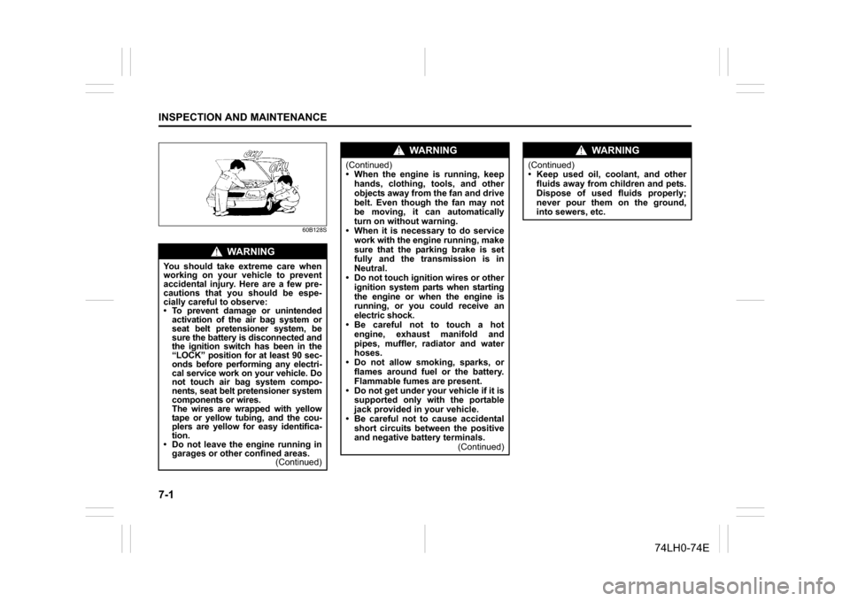
60B128S
WA R N I N G
You should take extreme care when
working on your vehicle to prevent
accidental injury. Here are a few pre-
cautions that you should be espe-
cially careful to observe:
To prevent damage or unintended
activation of the air bag system or
seat belt pretensioner system, be
sure the battery is disconnected and
the ignition switch has been in the
“LOCK” position for at least 90 sec-
onds before performing any electri-
cal service work on your vehicle. Do
not touch air bag system compo-
nents, seat belt pretensioner system
components or wires.
The wires are wrapped with yellow
tape or yellow tubing, and the cou-
plers are yellow for easy identifica-
tion.
Do not leave the engine running in
garages or other confined areas.
(Continued)
WA R N I N G
(Continued)
When the engine is running, keep
hands, clothing, tools, and other
objects away from the fan and drive
belt. Even though the fan may not
be moving, it can automatically
turn on without warning.
When it is necessary to do service
work with the engine running, make
sure that the parking brake is set
fully and the transmission is in
Neutral.
Do not touch ignition wires or other
ignition system parts when starting
the engine or when the engine is
running, or you could receive an
electric shock.
Be careful not to touch a hot
engine, exhaust manifold and
pipes, muffler, radiator and water
hoses.
Do not allow smoking, sparks, or
flames around fuel or the battery.
Flammable fumes are present.
Do not get under your vehicle if it is
supported only with the portable
jack provided in your vehicle.
Be careful not to cause accidental
short circuits between the positive
and negative battery terminals.
(Continued)
WA R N I N G
(Continued)
Keep used oil, coolant, and other
fluids away from children and pets.
Dispose of used fluids properly;
never pour them on the ground,
into sewers, etc.
Page 197 of 336
7-6
INSPECTION AND MAINTENANCE
74LH0-74E
Drive Belt(For Petrol Engine Model)
Make sure the drive belt tension is correct.
If the belt is too loose, insufficient battery
charging, engine overheating, poor power
steering, poor air conditioning, or exces-
sive belt wear can result. When you press
the belt with your thumb midway between
the pulleys, there should be a deflection
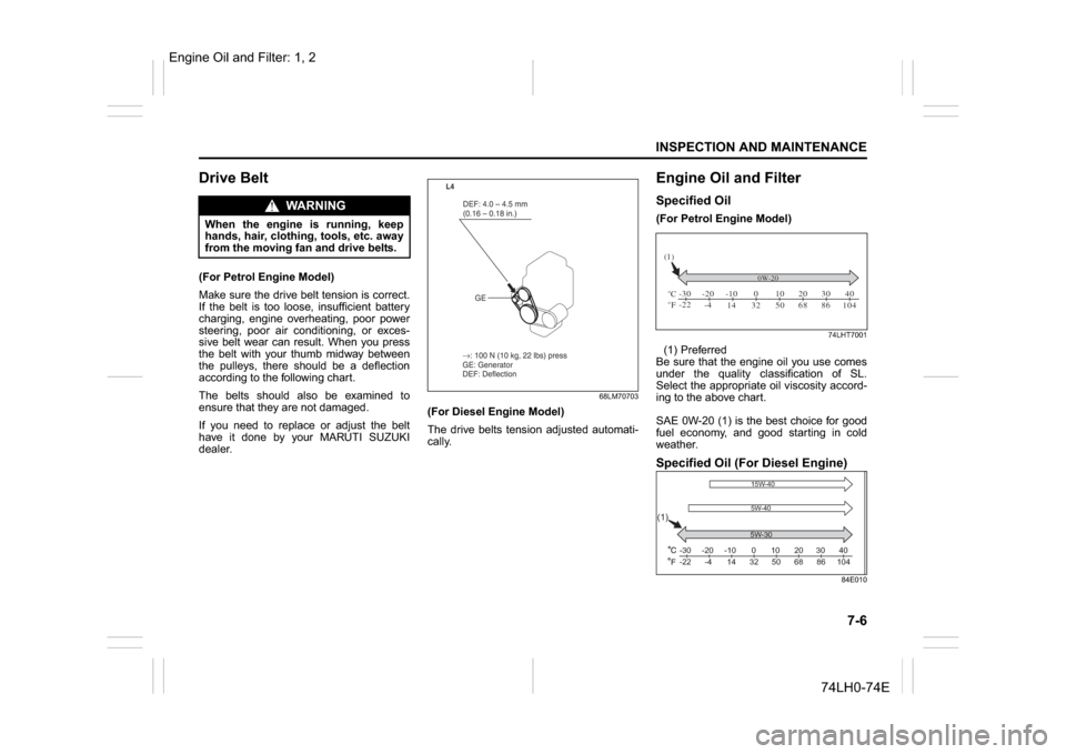
according to the following chart.
The belts should also be examined to
ensure that they are not damaged.
If you need to replace or adjust the belt
have it done by your MARUTI SUZUKI
dealer.
68LM70703
(For Diesel Engine Model)
The drive belts tension adjusted automati-
cally.
Engine Oil and FilterSpecified Oil (For Petrol Engine Model)
74LHT7001
(1) Preferred
Be sure that the engine oil you use comes
under the quality classification of SL.
Select the appropriate oil viscosity accord-
ing to the above chart.
SAE 0W-20 (1) is the best choice for good
fuel economy, and good starting in cold
weather. Specified Oil (For Diesel Engine)
84E010
When the engine is running, keep
hands, hair, clothing, tools, etc. away
from the moving fan and drive belts.
→ : 100 N (10 kg, 22 lbs) press
GE: Generator
DEF: Deflection DEF: 4.0 – 4.5 mm
(0.16 – 0.18 in.)
GE
L4
CFo o-30
-22 -20
-4 -10
14 32 50 68 86 104 010203040
(1)
0W-205W-30
(1)
-30
-22 -4 14
32506886 104
-20 -10 10 20
3040
0
15W-40
5W-40
Engine Oil and Filter: 1, 2
WA R N I N G
Page 198 of 336
7-7INSPECTION AND MAINTENANCE
74LH0-74E
(1) Preferred
Be sure that the engine oil you use comes
under the quality classification of ACEA
A5/B5. The recommended Engine oil is
5W30 A5/B5. Oil Level Check(For Petrol Engine Model)
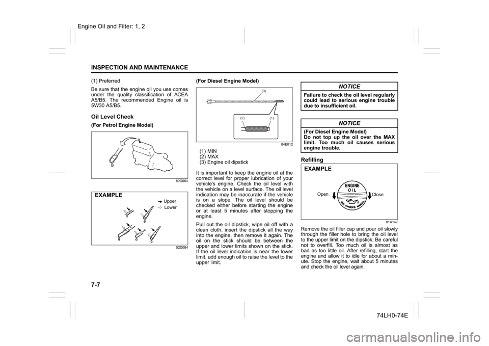
80G064
52D084
(For Diesel Engine Model)
84E012
(1) MIN
(2) MAX
(3) Engine oil dipstick
It is important to keep the engine oil at the
correct level for proper lubrication of your
vehicle’s engine. Check the oil level with
the vehicle on a level surface. The oil level
indication may be inaccurate if the vehicle
is on a slope. The oil level should be
checked either before starting the engine
or at least 5 minutes after stopping the
engine.
Pull out the oil dipstick, wipe oil off with a
clean cloth, insert the dipstick all the way
into the engine, then remove it again. The
oil on the stick should be between the
upper and lower limits shown on the stick.
If the oil level indication is near the lower
limit, add enough oil to raise the level to the
upper limit.
Refilling
81A147
Remove the oil filler cap and pour oil slowly
through the filler hole to bring the oil level
to the upper limit on the dipstick. Be careful
not to overfill. Too much oil is almost as
bad as too little oil. After refilling, start the
engine and allow it to idle for about a min-
ute. Stop the engine, wait about 5 minutes
and check the oil level again.
Upper
Lower
EXAMPLE
(3)
(2) (1)
NOTICE
Failure to check the oil level regularly
could lead to serious engine trouble
due to insufficient oil.
NOTICE
(For Diesel Engine Model)
Do not top up the oil over the MAX
limit. Too much oil causes serious
engine trouble.
Close Open
EXAMPLE
Engine Oil and Filter: 1, 2
Page 201 of 336
7-10
INSPECTION AND MAINTENANCE
74LH0-74E
Engine CoolantSelection of CoolantTo maintain optimum performance and
durability of your engine, use MARUTI
SUZUKI Genuine Coolant or equivalent.
This type of coolant is best for your cooling
system as it:
Helps maintain proper engine tempera-
ture.
Gives proper protection against freezing
and boiling.
Gives proper protection against corro-
sion and rust.
Failure to use the proper coolant can dam-
age your cooling system. Your authorized
MARUTI SUZUKI dealer can help you
select the proper coolant.
Coolant Level CheckCheck the coolant level at the reservoir
tank, not at the radiator. With the engine
cool, the coolant level should be between
the “FULL” and “LOW” marks.Adding Coolant
(For Petrol Engine Model)
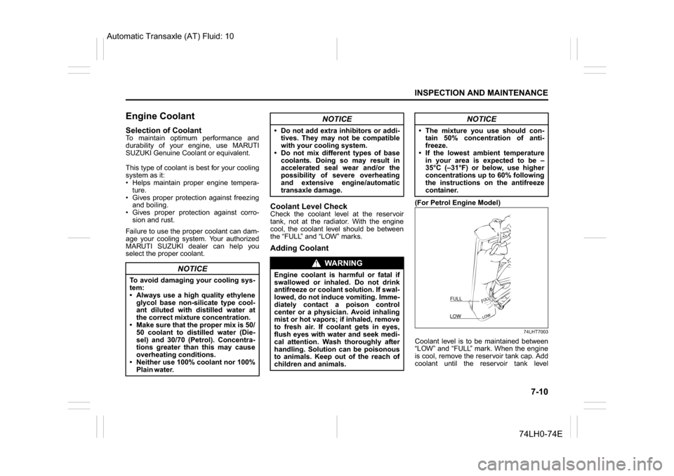
74LHT7003
Coolant level is to be maintained between
“LOW” and “FULL” mark. When the engine
is cool, remove the reservoir tank cap. Add
coolant until the reservoir tank level
NOTICE
To avoid damaging your cooling sys-
tem:
Always use a high quality ethylene
glycol base non-silicate type cool-
ant diluted with distilled water at
the correct mixture concentration.
Make sure that the proper mix is 50/
50 coolant to distilled water (Die-
sel) and 30/70 (Petrol). Concentra-
tions greater than this may cause
overheating conditions.
Neither use 100% coolant nor 100%
Plain water.
NOTICE
Do not add extra inhibitors or addi-
tives. They may not be compatible
with your cooling system.
Do not mix different types of base
coolants. Doing so may result in
accelerated seal wear and/or the
possibility of severe overheating
and extensive engine/automatic
transaxle damage.
WA R N I N G
Engine coolant is harmful or fatal if
swallowed or inhaled. Do not drink
antifreeze or coolant solution. If swal-
lowed, do not induce vomiting. Imme-
diately contact a poison control
center or a physician. Avoid inhaling
mist or hot vapors; if inhaled, remove
to fresh air. If coolant gets in eyes,
flush eyes with water and seek medi-
cal attention. Wash thoroughly after
handling. Solution can be poisonous
to animals. Keep out of the reach of
children and animals.
NOTICE
The mixture you use should con-
tain 50% concentration of anti-
freeze.
If the lowest ambient temperature
in your area is expected to be –
35°C (–31°F) or below, use higher
concentrations up to 60% following
the instructions on the antifreeze
container.
FULLLOWFULLLOW
Automatic Transaxle (AT) Fluid: 10
Page 203 of 336
7-12
INSPECTION AND MAINTENANCE
74LH0-74E
52KM122
For nickel spark plugs (traditional
type):You should inspect spark plugs periodically
for carbon deposits. When carbon accu-
mulates on a spark plug, a strong spark
may not be produced. Remove carbon
deposits with a wire or pin and adjust the
spark plug gap.
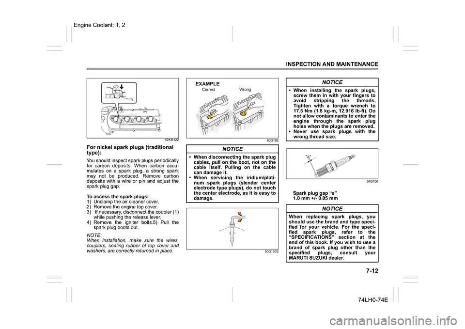
To access the spark plugs:
1) Unclamp the air cleaner cover.
2) Remove the engine top cover.
3) If necessary, disconnect the coupler (1)
while pushing the release lever.
4) Remove the igniter bolts.5) Pull the
spark plug boots out.
NOTE:
When installation, make sure the wires,
couplers, sealing rubber of top cover and
washers, are correctly returned in place.
60G102
60G160S54G106
Spark plug gap “a”
1.0 mm +/- 0.05 mm
NOTICE
When disconnecting the spark plug
cables, pull on the boot, not on the
cable itself. Pulling on the cable
can damage it.
When servicing the iridium/plati-
num spark plugs (slender center
electrode type plugs), do not touch
the center electrode, as it is easy to
damage.
NOTICE
When installing the spark plugs,
screw them in with your fingers to
avoid stripping the threads.
Tighten with a torque wrench to
17.5 Nm (1.8 kg-m, 12.916 lb-ft). Do
not allow contaminants to enter the
engine through the spark plug
holes when the plugs are removed.
Never use spark plugs with the
wrong thread size.
NOTICE
When replacing spark plugs, you
should use the brand and type speci-
fied for your vehicle. For the speci-
fied spark plugs, refer to the
“SPECIFICATIONS” section at the
end of this book. If you wish to use a
brand of spark plug other than the
specified plugs, consult your
MARUTI SUZUKI dealer.
Engine Coolant: 1, 2
Page 206 of 336
7-15
INSPECTION AND MAINTENANCE
74LH0-74E
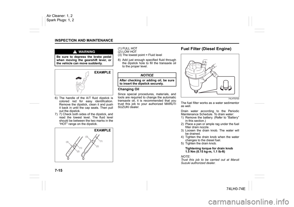
6) The handle of the A/T fluid dipstick is
colored red for easy identification.
Remove the dipstick, clean it and push
it back in until the cap seats. Then pull
out the dipstick.
7) 7) Check both sides of the dipstick, and
read the lowest level. The fluid level
should be between the two marks in the
“HOT” range on the dipstick.(1) FULL HOT
(2) LOW HOT
(3) The lowest point = Fluid level
8) Add just enough specified fluid through
the dipstick hole to fill the transaxle oil
to the proper level.
Changing Oil
Since special procedures, materials, and
tools are required to change the automatic
transaxle oil, it is recommended that you
trust this job to your authorized MARUTI
SUZUKI dealer.
Fuel Filter (Diesel Engine)
74LHT0703
The fuel filter works as a water sedimentor
as well.
Drain water according to the Periodic
Maintenance Schedule. To drain water:
1) Remove the battery. (Refer to “Battery”
in this section.)
2) Place a pan or ample rag under the fuel
filter drain nozzle.
3) Loosen the drain knob. The water will
be drained.
4) Tighten the drain knob when the water
changes to the diesel fuel.
5) Tighten the drain knob.
Tightening torque for drain knob
1.5 Nm (0.15 kg-m, 1.1 lb-ft)
NOTE:
Trust this job to be carried out at Maruti
Suzuki authorized dealer.
WA R N I N G
Be sure to depress the brake pedal
when moving the gearshift lever, or
the vehicle can move suddenly.
EXAMPLE
(1)(2) (3)(1)
(2)(3)
EXAMPLE
NOTICE
After checking or adding oil, be sure
to insert the dipstick securely.
Air Cleaner: 1, 2
Spark Plugs: 1, 2
Page 209 of 336
7-18
INSPECTION AND MAINTENANCE
74LH0-74E
Check that the steering wheel turns easily
and smoothly without rattling by turning it
all the way to the right and to the left while
driving very slowly in an open area. If the
amount of free play is outside the specifi-
cation or you find anything else to be
wrong, an inspection must be performed
by your MARUTI SUZUKI dealer.Tires
74LHT0704
The front and rear tire pressure specifica-
tions for your vehicle are listed on the Tire
Information Label. Both the front and rear
tires should have the specified tire pres-
sure.Tire InspectionInspect your vehicle’s tires at least once a
month by performing the following checks:
1) Measure the air pressure with a tire
gauge. Adjust the pressure if neces-
sary. Remember to check the spare
tire, too.
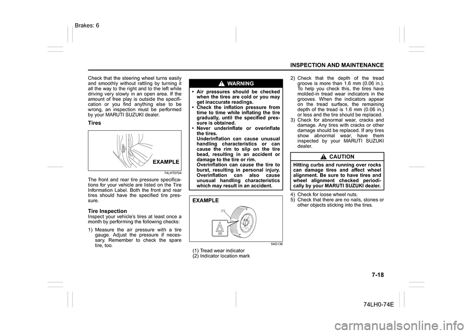
54G136
(1) Tread wear indicator
(2) Indicator location mark2) Check that the depth of the tread
groove is more than 1.6 mm (0.06 in.).
To help you check this, the tires have
molded-in tread wear indicators in the
grooves. When the indicators appear
on the tread surface, the remaining
depth of the tread is 1.6 mm (0.06 in.)
or less and the tire should be replaced.
3) Check for abnormal wear, cracks and
damage. Any tires with cracks or other
damage should be replaced. If any tires
show abnormal wear, have them
inspected by your MARUTI SUZUKI
dealer.
4) Check for loose wheel nuts.
5) Check that there are no nails, stones or
other objects sticking into the tires.
EXAMPLE
WA R N I N G
Air pressures should be checked
when the tires are cold or you may
get inaccurate readings.
Check the inflation pressure from
time to time while inflating the tire
gradually, until the specified pres-
sure is obtained.
Never underinflate or overinflate
the tires.
Underinflation can cause unusual
handling characteristics or can
cause the rim to slip on the tire
bead, resulting in an accident or
damage to the tire or rim.
Overinflation can cause the tire to
burst, resulting in personal injury.
Overinflation can also cause
unusual handling characteristics
which may result in an accident.EXAMPLE
CAUTION
Hitting curbs and running over rocks
can damage tires and affect wheel
alignment. Be sure to have tires and
wheel alignment checked periodi-
cally by your MARUTI SUZUKI dealer.
Brakes: 6
Page 214 of 336
7-23INSPECTION AND MAINTENANCE
74LH0-74E
The main fuse, primary fuses and some of
the individual fuses are located in the
engine compartment. If the main fuse
blows, no electrical component will func-
tion. If a primary fuse blows, no electrical
component in the corresponding load
group will function. When replacing the
main fuse, a primary fuse or an individual
fuse, use a MARUTI genuine replacement.
To remove a fuse, use the fuse puller pro-
vided in the fuse box. The amperage of
each fuse is shown in the back of the fuse
box cover.
60G111
NOTE:
Make sure that the fuse box always carries
spare fuses.Fuses under the Dash Board
74LHT0711
EXAMPLE
BLOWNOK
WA R N I N G
If the main fuse or a primary fuse
blows, be sure to have your vehicle
inspected by an authorized MARUTI
SUZUKI dealer. Always use a genuine
MARUTI replacement. Never use a
substitute such as a wire even for a
temporary repair, or extensive electri-
cal damage and a fire can result.EXAMPLE
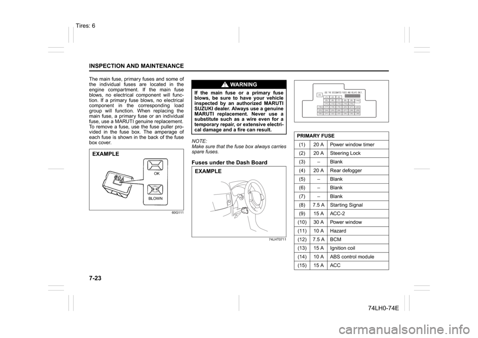
PRIMARY FUSE
(1) 20 A Power window timer
(2) 20 A Steering Lock
(3) – Blank
(4) 20 A Rear defogger
(5) – Blank
(6) – Blank
(7) – Blank
(8) 7.5 A Starting Signal
(9) 15 A ACC-2
(10) 30 A Power window
(11) 10 A Hazard
(12) 7.5 A BCM
(13) 15 A Ignition coil
(14) 10 A ABS control module
(15) 15 A ACC
(3)
(12)(10)
(13)
(36) (1) (2) (4)
(5)(6)
(7) (8)(9)
(11) (14) (15)
(16) (17) (18) (19) (20) (21) (22)
(23) (24) (25) (26) (27) (28) (29)
(30) (31) (32) (33) (34) (35)
Tires: 6
Page 217 of 336
7-26
INSPECTION AND MAINTENANCE
74LH0-74E
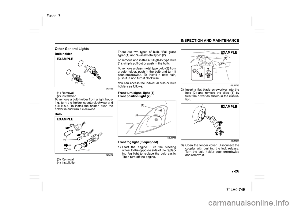
Other General LightsBulb holder
54G123
(1) Removal
(2) Installation
To remove a bulb holder from a light hous-
ing, turn the holder counterclockwise and
pull it out. To install the holder, push the
holder in and turn it clockwise.
Bulb
54G124
(3) Removal
(4) InstallationThere are two types of bulb, “Full glass
type” (1) and “Glass/metal type” (2).
To remove and install a full glass type bulb
(1), simply pull out or push in the bulb.
To remove a glass metal type bulb (2) from
a bulb holder, push in the bulb and turn it
counterclockwise. To install a new bulb,
push it in and turn it clockwise.
You can access the individual bulb or bulb
holders as follows.
Front turn signal light (1)
Front position light (2)
68LM714
Front fog light (if equipped)
1) Start the engine. Turn the steering
wheel to the opposite side of the replac-
ing fog light to replace the bulb easily.
Then turn off the engine.
68LM715
2) Insert a flat blade screwdriver into the
hole (2) and remove the clips (1) by
twist the driver as shown in the illustra-
tion.
80JM071
3) Open the fender cover. Disconnect the
coupler with pushing the lock release.
Turn the bulb holder counterclockwise
and remove it.
(1)
(1) (2)(2)
EXAMPLE
(1)
(2) (3)
(4)
EXAMPLE
EXAMPLEEXAMPLE
Fuses: 7
Page 225 of 336
8-2
EMERGENCY SERVICE
74LH0-74E
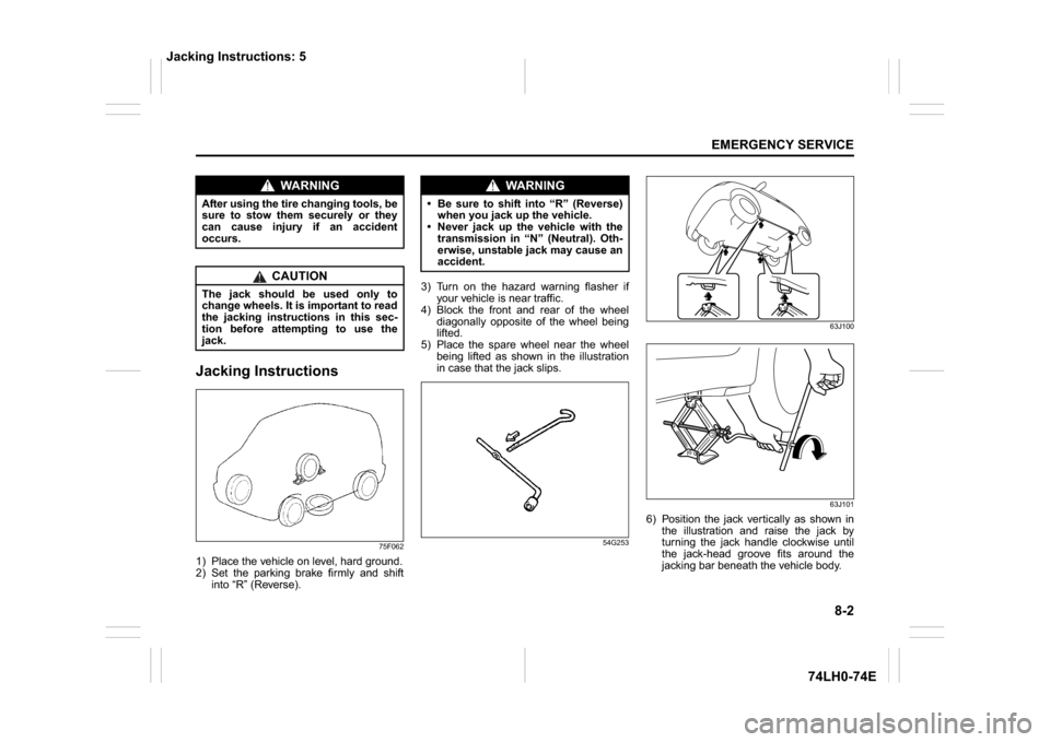
Jacking Instructions
75F062
1) Place the vehicle on level, hard ground.
2) Set the parking brake firmly and shift
into “R” (Reverse).3) Turn on the hazard warning flasher if
your vehicle is near traffic.
4) Block the front and rear of the wheel
diagonally opposite of the wheel being
lifted.
5) Place the spare wheel near the wheel
being lifted as shown in the illustration
in case that the jack slips.
54G25363J100
63J101
6) Position the jack vertically as shown in
the illustration and raise the jack by
turning the jack handle clockwise until
the jack-head groove fits around the
jacking bar beneath the vehicle body.
WA R N I N G
After using the tire changing tools, be
sure to stow them securely or they
can cause injury if an accident
occurs.
CAUTION
The jack should be used only to
change wheels. It is important to read
the jacking instructions in this sec-
tion before attempting to use the
jack.
WA R N I N G
Be sure to shift into “R” (Reverse)
when you jack up the vehicle.
Never jack up the vehicle with the
transmission in “N” (Neutral). Oth-
erwise, unstable jack may cause an
accident.
Jacking Instructions: 5