acc SUZUKI SWIFT 2017 5.G Repair Manual
[x] Cancel search | Manufacturer: SUZUKI, Model Year: 2017, Model line: SWIFT, Model: SUZUKI SWIFT 2017 5.GPages: 336, PDF Size: 6.24 MB
Page 138 of 336
5-11OTHER CONTROLS AND EQUIPMENT
74LH0-74E
Safety Information Notes on Discs
Precautions
When the inside of the vehicle is very
cold and the player is used soon after
switching on the heater, condensation
may form on the disc or the optical parts
of the player and proper playback may
not be possible. If condensation forms
on the disc, wipe it off with a soft cloth. If
condensation forms on the optical parts
of the player, do not use the player for
about one hour. This will allow the con-
densation to disappear normally.
Driving on extremely bumpy roads which
cause severe vibrations may cause
sound to skip.
This unit uses a precision mechanism.
Even in the event that trouble arises,
never open the case, disassemble the
unit, or lubricate the rotating parts.
Please bring the unit to an authorized
MARUTI SUZUKI dealer.Cautions on Handling
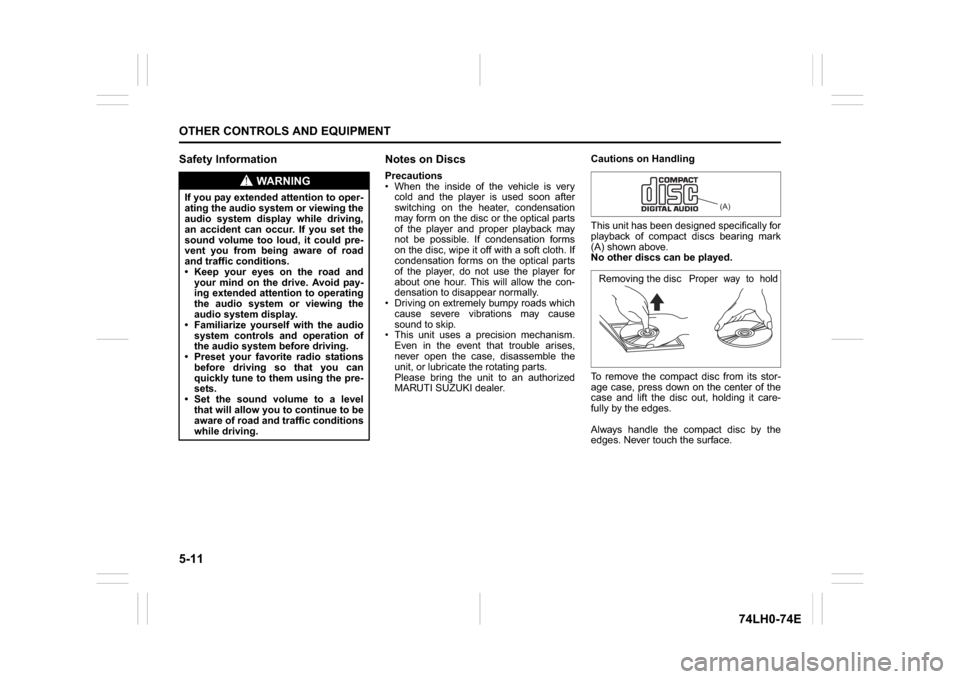
This unit has been designed specifically for
playback of compact discs bearing mark
(A) shown above.
No other discs can be played.
To remove the compact disc from its stor-
age case, press down on the center of the
case and lift the disc out, holding it care-
fully by the edges.
Always handle the compact disc by the
edges. Never touch the surface.
WA R N I N G
If you pay extended attention to oper-
ating the audio system or viewing the
audio system display while driving,
an accident can occur. If you set the
sound volume too loud, it could pre-
vent you from being aware of road
and traffic conditions.
Keep your eyes on the road and
your mind on the drive. Avoid pay-
ing extended attention to operating
the audio system or viewing the
audio system display.
Familiarize yourself with the audio
system controls and operation of
the audio system before driving.
Preset your favorite radio stations
before driving so that you can
quickly tune to them using the pre-
sets.
Set the sound volume to a level
that will allow you to continue to be
aware of road and traffic conditions
while driving.
(A)
Removing the disc
Proper way to hold
the compact disc
Page 141 of 336
5-14
OTHER CONTROLS AND EQUIPMENT
74LH0-74E
Adjusting the AVC (Auto volume con-
trol)The Auto Volume Control (AVC) function
automatically adjusts (increases/decreases)
the sound volume in accordance with vehicle
speed. The AVC control is provided with
three selectable levels (LEVEL OFF, 1, 2, 3).
The range of volume adjustment increases
together with the LEVEL number.1) Press the TUNE FOLDER PUSH
SOUND knob (2) until the AVC adjust-
ment mode is selected.
2) Turn the TUNE FOLDER PUSH
SOUND knob (2) to select the desired
AVC adjustment level. (Initial setting:
LEVEL 2)
Preset-EQ
Preset-EQ calls up various sound types in
accordance with the listening music type.
1) Press the TUNE FOLDER PUSH
SOUND knob (2) several times until
“PRESET-EQ” appears.
2) Turn the TUNE FOLDER PUSH
SOUND knob (2).
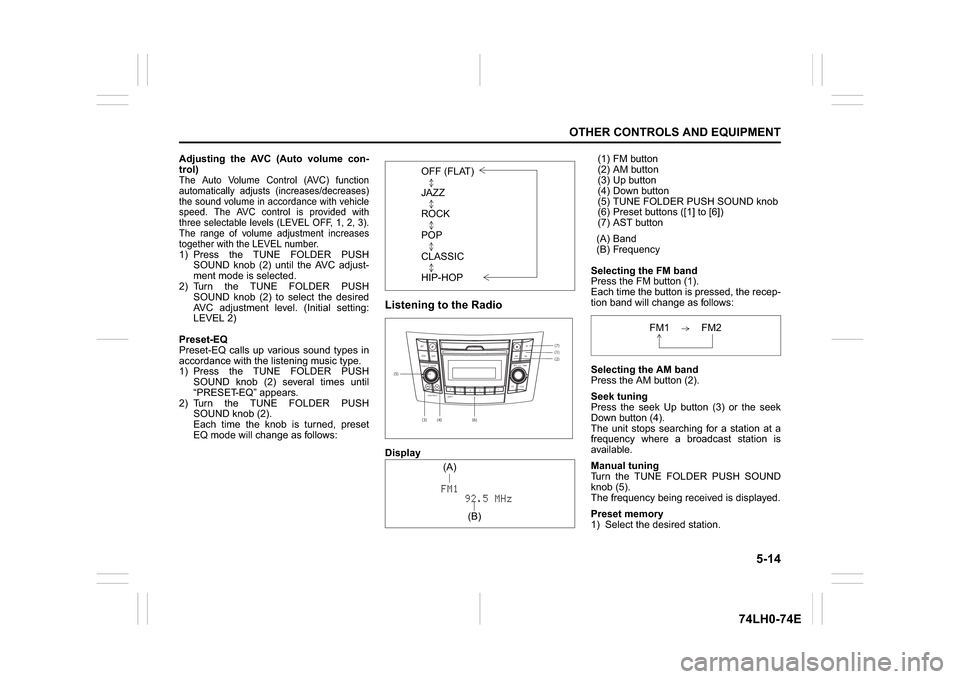
Each time the knob is turned, preset
EQ mode will change as follows:
Listening to the RadioDisplay(1) FM button
(2) AM button
(3) Up button
(4) Down button
(5) TUNE FOLDER PUSH SOUND knob
(6) Preset buttons ([1] to [6])
(7) AST button
(A) Band
(B) Frequency
Selecting the FM band
Press the FM button (1).
Each time the button is pressed, the recep-
tion band will change as follows:
Selecting the AM band
Press the AM button (2).
Seek tuning
Press the seek Up button (3) or the seek
Down button (4).
The unit stops searching for a station at a
frequency where a broadcast station is
available.
Manual tuning
Turn the TUNE FOLDER PUSH SOUND
knob (5).
The frequency being received is displayed.
Preset memory
1) Select the desired station. OFF (FLAT)
JAZZ
ROCK
POP
CLASSIC
HIP-HOP(5)
(6)(7)
B S U
CD
2
3 4 5 6
SEEK/TRACK
AS
AMFM RPT
RDM
DISP
PUSHSOUND
TUNE/FLD
VOL PWRPUSH
11
MENU
(1)(2)
(3)
(4)(A)
(B)
FM1 FM2
Page 148 of 336
5-21OTHER CONTROLS AND EQUIPMENT
74LH0-74E
Notes on USB deviceCompatible USB devices
USB Mass Storage Class
For details as to whether your USB
memory/USB Audio is compatible with
USB Mass Storage Class, please con-
tact the USB memory/USB Audio manu-
facturer.
USB Standard Compatibility 1.1/2.0 Full
Speed
File System FAT12/16/32, VFAT
Maximum current less than 1.0 A
If devices such as USB hub, extension
cable are connected to the audio sys-
tem, it may not be recognized. In such
case connect the USB device directly to
the audio system.
Devices such as MP3 player/Mobile
phone/digital camera may not be recog-
nized by the audio system for playing
music.
USB device connection
When connecting a USB device, make
sure that the connector is pushed all the
way into the port.
Do not leave the USB device for long
periods of time in places inside the vehi-
cle where the temperature can rise too
high.
Back up any important data beforehand.
We cannot accept responsibility for any
lost data.
It is recommended not to connect a USB
device that contains data files other than
MP3/WMA/AAC format.Recording MP3/WMA/AAC files on a
USB device
Playback or display may not be possible
depending on the type of USB device in
use or the condition of the recording.
Depending on the connected USB mem-
ory, the files may be played in different
order from the order that the files were
stored.
Compression formats
MP3
Bit rate
:
MPEG1 Audio Layer III: 32 k - 320 kbps
MPEG2 Audio Layer III: 8 k - 160 kbps
MPEG2.5 Audio Layer III: 8 k - 160 kbps Sampling frequency
:
MPEG1 Audio Layer III: 32 k/44.1 k/48 kHz
MPEG2 Audio Layer III: 16 k/22.05 k/24 kHz
MPEG2.5 Audio Layer III: 8 k/11.025 k/12 kHzWMA (Ver. 7, Ver. 8, Ver. 9*)
Bit rate: CBR 32 k -320 kbps
Sampling frequency: 32 k/44.1 k/48 kHz
* WMA 9 Professional/LossLess/Voice are
not supported.
AAC*
Bit rate: ABR 16k - 320 kbbs
Sampling frequency: 32 k/44.1 k/48 kHz
* Apple Lossless is not supported.
Maximum number of files/folders
Maximum number of files: 2500
Maximum number of files in a folder: 255
Maximum depth of tree structure: 8
Maximum number of folders: 255
(Root folder is included.)
Listening to an iPod
®
74LHT5007
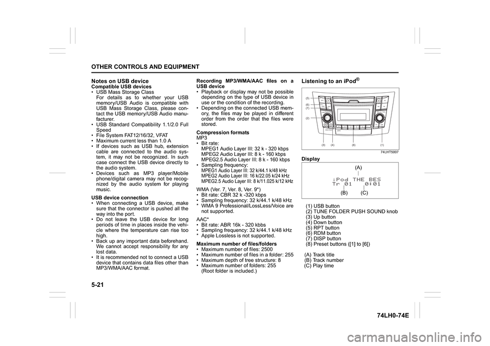
Display
(1) USB button
(2) TUNE FOLDER PUSH SOUND knob
(3) Up button
(4) Down button
(5) RPT button
(6) RDM button
(7) DISP button
(8) Preset buttons ([1] to [6[)
(A) Track title
(B) Track number
(C) Play time(2) (6)
B S U
CD
2
3 4 5 6
SEEK/TRACK
AS
AMFM RPT
RDM
DISP
PUSHSOUND
TUNE/FLD
VOLPWRPUSH
11
MENU
(3)
(5)
(4) (7)
(1)
(8)
(C)(A)
(B)
Page 150 of 336
5-23OTHER CONTROLS AND EQUIPMENT
74LH0-74E
Notes on iPod
®
Supported iPod
®
® touch (5th generation)
® touch (4th generation)
® touch (3rd generation)
® touch (2nd generation)
® touch (1st generation)
® classic
® nano (7th generation)
® nano (6th generation)
® nano (5th generation)
® nano (4th generation)
® nano (3rd generation)
® nano (2nd generation)
® nano (1st generation)
® (5th generation)
iPhone® 6 Plus
iPhone® 6
iPhone® 5S
iPhone® 5
iPhone® 4S
iPhone® 4
iPhone® 3GS
iPhone® 3G
iPhone®
* Some functions may not be available
depending on the model of iPod
®.
*iPod
® is a trademark of Apple Inc., regis-
tered in the U.S. and other countries.
* iPhone® is a trademark of Apple Inc.,
registered in the U.S. and other coun-
tries.
* Apple is not responsible for the operation
of this device or its compliance with
safety and regulatory standards.iPod
® connection
Make sure to detach the iPod
® after
pressing the engine switch to change the
ignition mode to LOCK. The iPod® may
not be shut down when it is being con-
nected and may result in battery deple-
tion.
Please do not connect iPod
® accesso-
ries such as an iPod
® remote control or
headphones while connecting the iPod
®
with the unit. The unit may not operate
correctly.
AUX Function
74LHT5011
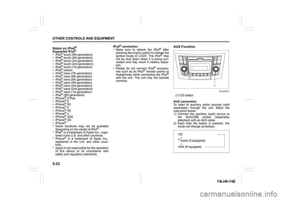
(1) CD button
AUX connection
To listen to auxiliary audio sources (sold
separately) through the unit, follow the
instruction below.
1) Connect the auxiliary audio source to
the AUX/USB socket (separately
attached) with an AUX cable.
2) Each time the button is pressed, the
mode will change as follows:
B S U
CD
2
3 4 5 6
SEEK/TRACK
AS
AMFM RPT
RDM
DISP
PUSHSOUND
TUNE/FLD
VOL
PWRPUSH
11
MENU
(1)
CD® audio (if equipped)
AUX (if equipped)
Page 160 of 336
5-33OTHER CONTROLS AND EQUIPMENT
74LH0-74E
List of audio devices (List Audio)
Follow the instructions below to display the
names of the registered audio devices in
sequence.
1) Press the
® setup button (6).
The
® setup menu will be displayed.
2) Turn the TUNE FOLDER PUSH
SOUND knob (2) to select “Setup ”, and
press the knob (2) to determine the
selection.
3) Turn the TUNE FOLDER PUSH
SOUND knob (2) to select “List Audio”,
and press the knob (2) to determine the
selection. The names of registered
audio devices will be displayed in
sequence.
NOTE:
When selecting “Go Back”, the previous
menu will be displayed.
Passkey setting (Set Passkey)
Follow the instructions below to set the
security number (Passkey).
1) Press the
® setup button (6).
The
® setup menu will be displayed.
2) Turn the TUNE FOLDER PUSH
SOUND knob (2) to select “Setup ”, and
press the knob (2) to determine the
selection.
3) Turn the TUNE FOLDER PUSH
SOUND knob (2) to select “Passkey”,
and press the knob (2) to determine the
selection.
4) Turn the TUNE FOLDER PUSH
SOUND knob (2) to select “New Pass-key”, and press the knob (2) to deter-
mine the selection.
5) Press or turn the TUNE FOLDER
PUSH SOUND knob (2) to select “Con-
firm”.
6) Turn the TUNE FOLDER PUSH
SOUND knob (2) to select a number for
the first digit, and press the knob (2) to
determine the selection. Select and
determine numbers for the second,
third and fourth digits in order in the
same manner. When not entering up to
the eighth digit, enter blanks for the
successive digits.
7) Turn the TUNE FOLDER PUSH
SOUND knob (2) to determine the
passkey setting.
NOTE:
When selecting “Go Back”, the previous
menu will be displayed.
Deletion of audio device information
(Delete Audio)
Follow the instructions below to delete the
registered information of audio device.
1) Press the
® setup button (6).
The
® setup menu will be displayed.
2) Turn the TUNE FOLDER PUSH
SOUND knob (2) to select “Setup ”, and
press the knob (2) to determine the
selection.
3) Turn the TUNE FOLDER PUSH
SOUND knob (2) to select “List Audio”,
and press the knob (2) to determine the
selection.4) Turn the TUNE FOLDER PUSH
SOUND knob (2) to select an audio
device to be deleted, and press the
knob (2) to determine the selection.
5) Turn the TUNE FOLDER PUSH
SOUND knob (2) to select “Delete”, and
press the knob (2) to determine the
selection.
6) Turn the TUNE FOLDER PUSH
SOUND knob (2) to select “Delete?”,
and press the knob (2) to determine the
selection.
7) Turn the TUNE FOLDER PUSH
SOUND knob (2) to select “Confirm”,
and press the knob (2) to complete the
deletion.
NOTE:
When selecting “Go Back”, the previous
menu will be displayed.
Disclaimer for
® function
Depending on the mobile phone models,
some phones may not be compatible
fully or partially (some function may be
restricted).
Connectivity or voice quality may get
affected depending on circumstances.
After the ignition switch is turned to the
“ON” position, the audio system takes
few seconds to detect and connect to the® device (if already paired).
Make sure that you are aware of all
applicable local laws and accordingly
use device.
Page 162 of 336
5-35OTHER CONTROLS AND EQUIPMENT
74LH0-74E
The anti-theft function is intended to dis-
courage thefts, such as that the audio sys-
tem becomes inoperable when it is
installed on other vehicles.
This function works by entering a Personal
Identification Number (PIN).
When the unit is disconnected from its
power source, such as when the audio
system is removed or the battery is discon-
nected, the unit will become inoperable
until the PIN is reentered.
Setting the Anti-Theft Function
1) Press the VOL PUSH POWER knob (1)
to power off.
2) Hold down the buttons numbered [1]
and [6] of the Preset buttons (2) and
press the VOL PUSH POWER knob (1).
“SECURITY” will be displayed.
3) Press the Up button (3) and the button
numbered [1] of the Preset buttons (2)
simultaneously.
4) Enter a 4-digit number to be registered
as PIN using the buttons numbered [1] -
[4] of the Preset buttons (2).
5) Hold down the TUNE FOLDER PUSH
SOUND knob (4) for 1 second or longer
to set the anti-theft function.
NOTE:
Take a note of the registered PIN and keep
it for the future use.Canceling the anti-theft feature
To cancel the anti-theft function, delete the
registered PIN.
1) Press the VOL PUSH POWER knob (1)
to power off.
2) Hold down the buttons numbered [1]
and [6] of the Preset buttons (2) and
press the VOL PUSH POWER knob (1).
“PIN ENTRY” will be displayed.
3) Press the Up button (3) and the button
numbered [1] of the Preset buttons (2)
simultaneously.
4) Enter a 4-digit number to be registered
as PIN using the buttons numbered [1] -
[4] of the Preset buttons (2).
5) Hold down the TUNE FOLDER PUSH
SOUND knob (4) for 1 second or longer
to delete the registered PIN. The indi-
cation “----” will be displayed and the
anti-theft function will be canceled.
NOTE:
To change your PIN, first delete your cur-
rent PIN, then set a new one.Confirming the Personal Identification
Number (PIN)
When the main power source is discon-
nected such as when the battery is
replaced, etc, it is required to enter the PIN
to make the unit operable again.
1) Set the ignition switch to the “ACC”
position.
“SECURITY” will be displayed.
2) Press the Up button (3) and the button
numbered [1] of the Preset buttons (2)
simultaneously.
3) Enter a 4-digit number to be registered
as PIN using the buttons numbered [1] -
[4] of the Preset buttons (2).
4) Hold down TUNE FOLDER PUSH
SOUND knob (4) for 1 second or lon-
ger.
When the PIN same as registered is
entered, the power of the audio system
will be turned off automatically and it
will become operable again.
NOTE:
If an incorrect PIN is entered, “ERROR”
and the total number of incorrect entry
attempts will be displayed.
If an incorrect PIN is entered 10 times,
“HELP” will be displayed and the audio
system will become inoperable.
Page 163 of 336
5-36
OTHER CONTROLS AND EQUIPMENT
74LH0-74E
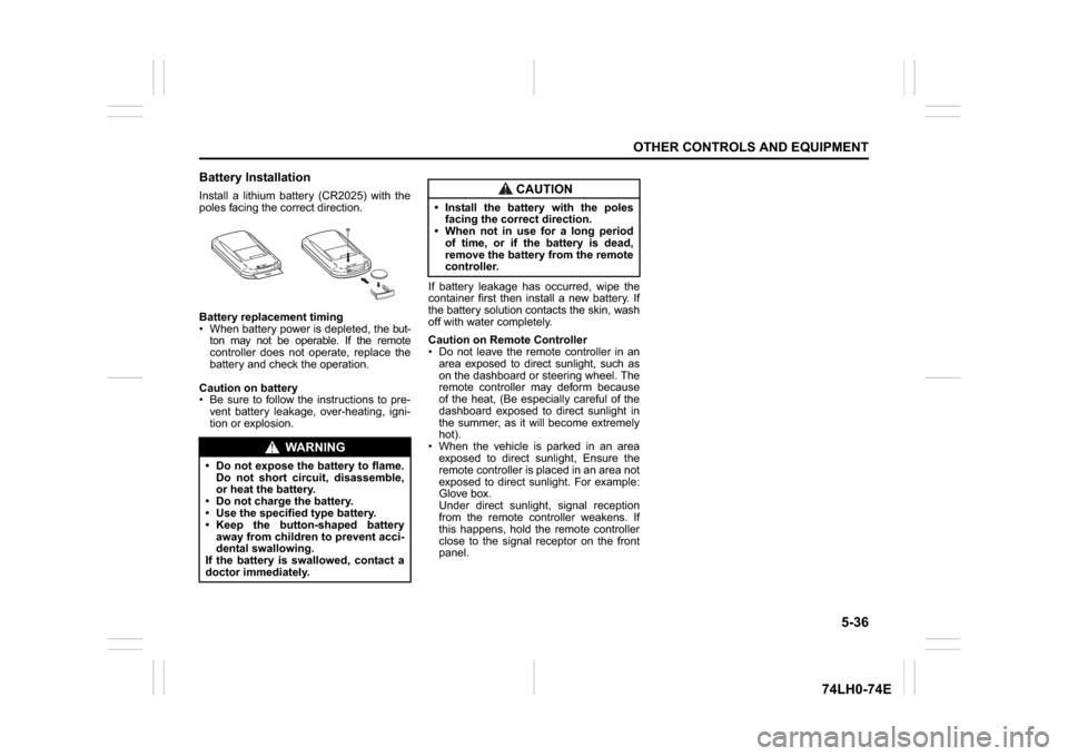
Battery InstallationInstall a lithium battery (CR2025) with the
poles facing the correct direction.
Battery replacement timing
When battery power is depleted, the but-
ton may not be operable. If the remote
controller does not operate, replace the
battery and check the operation.
Caution on battery
Be sure to follow the instructions to pre-
vent battery leakage, over-heating, igni-
tion or explosion.If battery leakage has occurred, wipe the
container first then install a new battery. If
the battery solution contacts the skin, wash
off with water completely.
Caution on Remote Controller
Do not leave the remote controller in an
area exposed to direct sunlight, such as
on the dashboard or steering wheel. The
remote controller may deform because
of the heat, (Be especially careful of the
dashboard exposed to direct sunlight in
the summer, as it will become extremely
hot).
When the vehicle is parked in an area
exposed to direct sunlight, Ensure the
remote controller is placed in an area not
exposed to direct sunlight. For example:
Glove box.
Under direct sunlight, signal reception
from the remote controller weakens. If
this happens, hold the remote controller
close to the signal receptor on the front
panel.
WA R N I N G
Do not expose the battery to flame.
Do not short circuit, disassemble,
or heat the battery.
Do not charge the battery.
Use the specified type battery.
Keep the button-shaped battery
away from children to prevent acci-
dental swallowing.
If the battery is swallowed, contact a
doctor immediately.
CAUTION
Install the battery with the poles
facing the correct direction.
When not in use for a long period
of time, or if the battery is dead,
remove the battery from the remote
controller.
Page 174 of 336
5-47OTHER CONTROLS AND EQUIPMENT
74LH0-74E
Fuel Filler CapSwift
68LM522
Dzire
74LHT0511
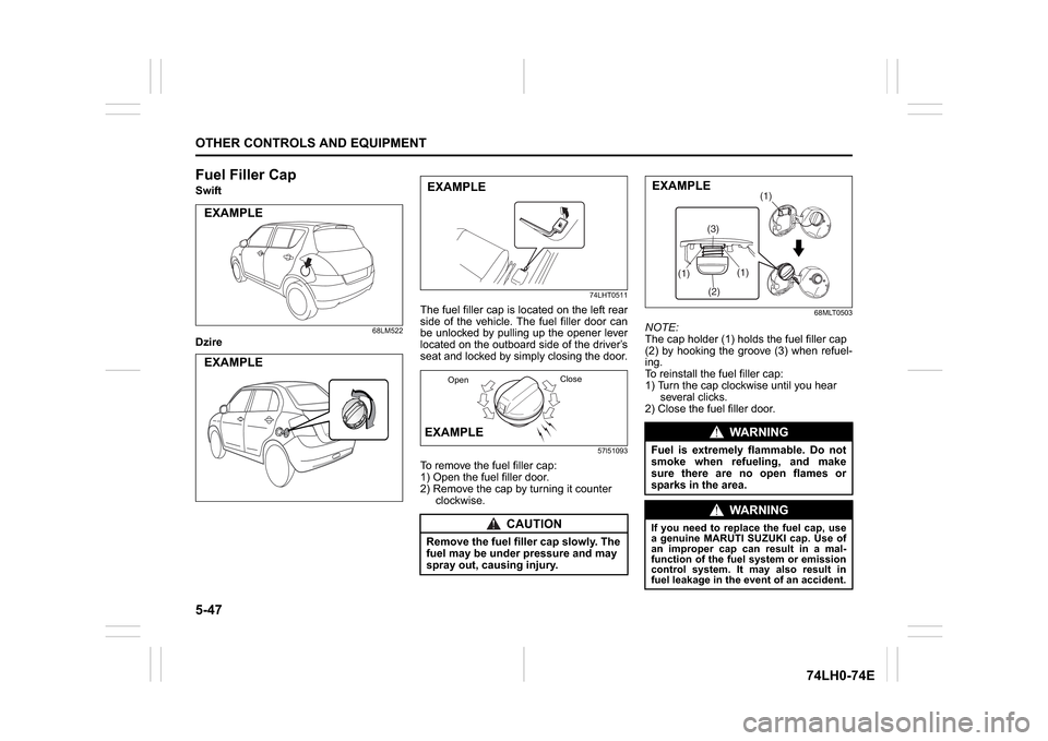
The fuel filler cap is located on the left rear
side of the vehicle. The fuel filler door can
be unlocked by pulling up the opener lever
located on the outboard side of the driver’s
seat and locked by simply closing the door.
57l51093
To remove the fuel filler cap:
1) Open the fuel filler door.
2) Remove the cap by turning it counter
clockwise.
68MLT0503
NOTE:
The cap holder (1) holds the fuel filler cap
(2) by hooking the groove (3) when refuel-
ing.
To reinstall the fuel filler cap:
1) Turn the cap clockwise until you hear
several clicks.
2) Close the fuel filler door.
EXAMPLEEXAMPLE
CAUTION
Remove the fuel filler cap slowly. The
fuel may be under pressure and may
spray out, causing injury.EXAMPLEEXAMPLE
OpenClose
WA R N I N G
Fuel is extremely flammable. Do not
smoke when refueling, and make
sure there are no open flames or
sparks in the area.
WA R N I N G
If you need to replace the fuel cap, use
a genuine MARUTI SUZUKI cap. Use of
an improper cap can result in a mal-
function of the fuel system or emission
control system. It may also result in
fuel leakage in the event of an accident.
(1)
(2)(3)(1)
(1)
EXAMPLE
Page 175 of 336
5-48
OTHER CONTROLS AND EQUIPMENT
74LH0-74E
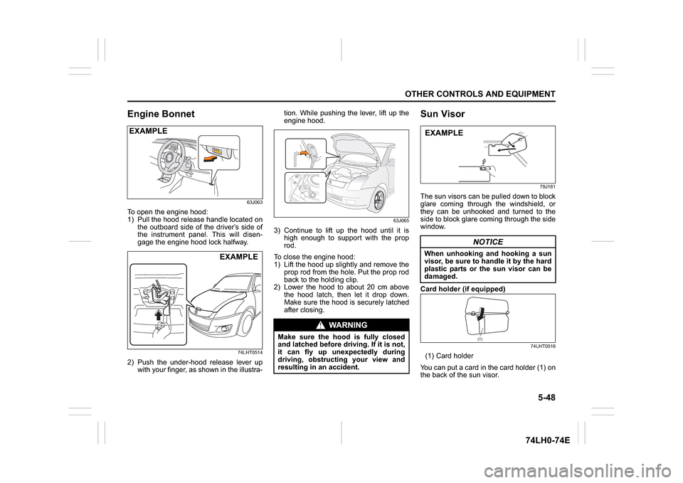
Engine Bonnet
63J063
To open the engine hood:
1) Pull the hood release handle located on
the outboard side of the driver’s side of
the instrument panel. This will disen-
gage the engine hood lock halfway.
74LHT0514
2) Push the under-hood release lever up
with your finger, as shown in the illustra-tion. While pushing the lever, lift up the
engine hood.
63J065
3) Continue to lift up the hood until it is
high enough to support with the prop
rod.
To close the engine hood:
1) Lift the hood up slightly and remove the
prop rod from the hole. Put the prop rod
back to the holding clip.
2) Lower the hood to about 20 cm above
the hood latch, then let it drop down.
Make sure the hood is securely latched
after closing.
Sun Visor
79J161
The sun visors can be pulled down to block
glare coming through the windshield, or
they can be unhooked and turned to the
side to block glare coming through the side
window.
Card holder (if equipped)
74LHT0516
(1) Card holder
You can put a card in the card holder (1) on
the back of the sun visor.
EXAMPLE
EXAMPLE
WA R N I N G
Make sure the hood is fully closed
and latched before driving. If it is not,
it can fly up unexpectedly during
driving, obstructing your view and
resulting in an accident.
NOTICE
When unhooking and hooking a sun
visor, be sure to handle it by the hard
plastic parts or the sun visor can be
damaged.EXAMPLE
(1)
Page 176 of 336
5-49OTHER CONTROLS AND EQUIPMENT
74LH0-74E
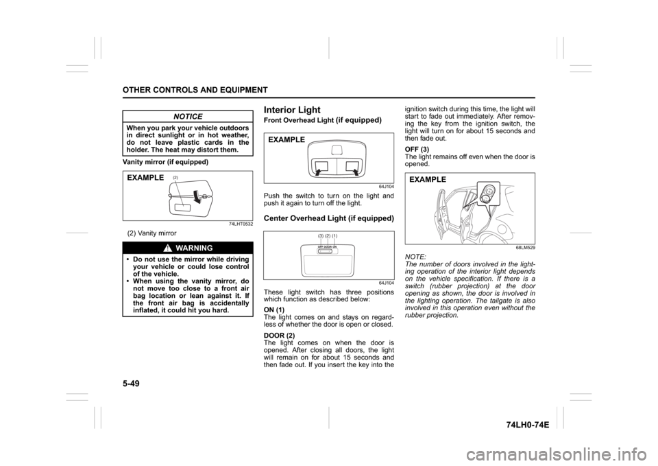
Vanity mirror (if equipped)
74LHT0532
(2) Vanity mirror
Interior Light Front Overhead Light
(if equipped)
64J104
Push the switch to turn on the light and
push it again to turn off the light.Center Overhead Light (if equipped)
64J104
These light switch has three positions
which function as described below:
ON (1)
The light comes on and stays on regard-
less of whether the door is open or closed.
DOOR (2)
The light comes on when the door is
opened. After closing all doors, the light
will remain on for about 15 seconds and
then fade out. If you insert the key into theignition switch during this time, the light will
start to fade out immediately. After remov-
ing the key from the ignition switch, the
light will turn on for about 15 seconds and
then fade out.
OFF (3)
The light remains off even when the door is
opened.
68LM529
NOTE:
The number of doors involved in the light-
ing operation of the interior light depends
on the vehicle specification. If there is a
switch (rubber projection) at the door
opening as shown, the door is involved in
the lighting operation. The tailgate is also
involved in this operation even without the
rubber projection.
NOTICE
When you park your vehicle outdoors
in direct sunlight or in hot weather,
do not leave plastic cards in the
holder. The heat may distort them.
WA R N I N G
Do not use the mirror while driving
your vehicle or could lose control
of the vehicle.
When using the vanity mirror, do
not move too close to a front air
bag location or lean against it. If
the front air bag is accidentally
inflated, it could hit you hard.
(2)
EXAMPLE
EXAMPLE
(1)(2)(3)
EXAMPLE