Set clock SUZUKI SWIFT 2017 5.G Owners Manual
[x] Cancel search | Manufacturer: SUZUKI, Model Year: 2017, Model line: SWIFT, Model: SUZUKI SWIFT 2017 5.GPages: 336, PDF Size: 6.24 MB
Page 72 of 336
2-53
BEFORE DRIVING
74LH0-74E
Information Display
74LM02001
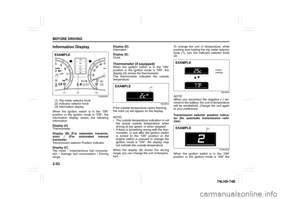
(1) Trip meter selector knob
(2) Indicator selector knob
(3) Information display
When the ignition switch is in the “ON”
position or the ignition mode is "ON", the
information display shows the following
information.
Display (A)
Thermometer
Display (B) (For automatic transmis-
sion) / (For automated manual
transaxle)
Transmission selector Position Indicator
Display (C)
Trip meter / Instantaneous fuel consump-
tion / Average fuel consumption / Driving
range.Display (D)
Odometer
Display (E)
Clock
Thermometer (if equipped)When the ignition switch is in the “ON”
position or the ignition mode is "ON", the
display (A) shows the thermometer.
The thermometer indicates the outside
temperature.
68LM258
If the outside temperature nears freezing,
the mark (a) will appear on the display.
NOTE:
• The outside temperature indication is not
the actual outside temperature when
driving at low speed, or when stopped.
• If there is something wrong with the ther-
mometer, or just after the ignition switch
is turned to the “ON” position or the
engine switch is pressed to change the
ignition mode is “ON”, the display may
not indicate the outside temperature.
When the display (B) shows the driving
range, you can change the unit of tempera-
ture.To change the unit of temperature, while
pushing and holding the trip meter selector
knob (1), turn the indicator selector knob
(2).
68LM259
NOTE:
When you reconnect the negative (–) ter-
minal to the battery, the unit of temperature
will be reinitialized. Change the unit again
to your preference.
Transmission selector position indica-
tor (for automatic transmission vehi-
cles)
74LM02002
When the ignition switch is in the “ON”
position or the ignition mode is “ON” the
(1) (2)(3)
(D)(B) (A)
(C)(E)
EXAMPLE
(a)EXAMPLE
EXAMPLE
(Initial
setting)
(b)EXAMPLE
Page 75 of 336
2-56
BEFORE DRIVING
74LH0-74E
• When you reconnect the negative (–)
terminal to the battery, the unit of the
average fuel consumption will be reini-
tialized. Change the unit again to your
preference.
Driving range
If you selected driving range the last time
you drove the vehicle, the display indicates
“---” for a few seconds and then indicates
the current driving range when the ignition
switch is turned to the “ON” position or the
engine switch is pressed to change the
ignition mode is “ON”.
The driving range shown in the display is
the approximate distance you can drive
until the fuel gauge indicates “E”, based on
current driving conditions.
When the low fuel warning light comes on,
the display “---” will appear.
If the low fuel warning light comes on, fill
the fuel tank immediately regardless of the
value of driving range shown in the display.
As the driving range after refueling is cal-
culated based on the most recent driving
condition, the value is different each time
you refuel.
NOTE:
• If you refuel when the ignition switch is in
the “ON” position or the ignition mode is
"ON", the driving range may not indicate
the correct value.
• When you reconnect the negative (–)
terminal to the battery, the value of driv-ing range will be shown after driving for a
while.
Odometer
When the ignition switch is in the “ON”
position or the ignition mode is "ON", the
display (C) shows the odometer.
The odometer records the total distance
the vehicle has been driven.
Clock
When the ignition switch is in the “ON”
position or the ignition mode is "ON", the
display (D) shows the time.
To change the time indication:
1) Push the trip meter selector knob (1)
and the indicator selector knob (2)
together.
2) To change the hour indication, turn the
indicator selector knob (2) left or right
repeatedly when the hour indication
blinks. To change the hour indication
quickly, turn and hold the indicator
selector knob (2). To set the hour indi-
cation, push the indicator selector knob
(2) and the minute indication will blink.3) To change the minute indication, turn
the indicator selector knob (2) left or
right repeatedly when the minute indi-
cation blinks. To change the minute
indication quickly, turn and hold the
indicator selector knob (2). To set the
minute indication, push the indicator
selector knob (2).
NOTE:
When you reconnect the negative (–) ter-
minal to the battery, the clock indication will
be reinitialized. Change the indication
again to your preference.
NOTICE
Keep track of your odometer reading
and check the maintenance sched-
ule regularly for required services.
Increased wear or damage to certain
parts can result from failure to per-
form required services at the proper
mileage intervals.
WA R N I N G
If you attempt to adjust the display
while driving, you could lose control
of the vehicle.
Do not attempt to adjust the display
while driving.
Page 140 of 336
5-13OTHER CONTROLS AND EQUIPMENT
74LH0-74E
(if equipped)
The
® word mark and logo are registered
trademarks and are owned by the SIG,
Ink.
Stop using this unit and a
® ready
device whenever requested.
This unit shares the communication fre-
quency with other private or public wireless
communication equipment such as a wire-
less LAN and other wireless communica-
tion radios.
You should stop using this unit whenever
you are notified that your unit disturbs
other wireless communication immediately.
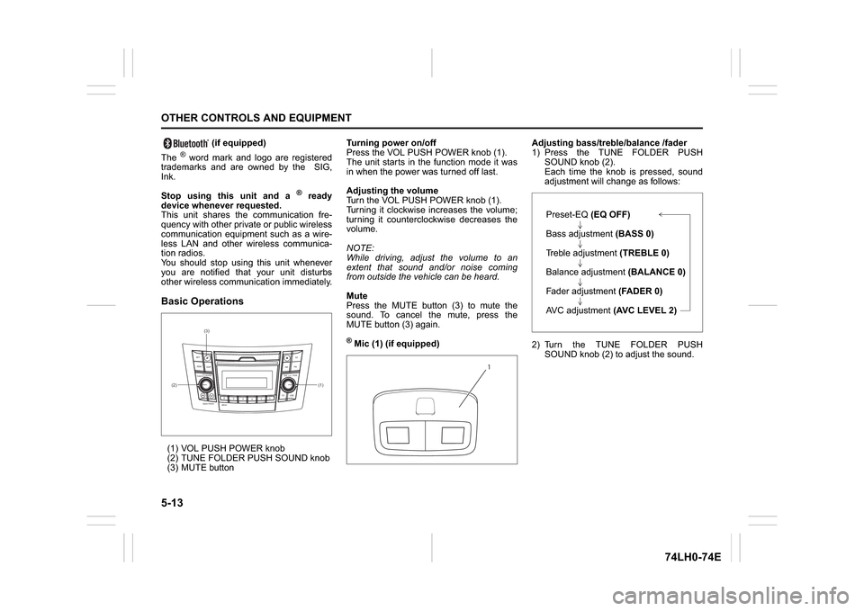
Basic Operations(1) VOL PUSH POWER knob
(2) TUNE FOLDER PUSH SOUND knob
(3) MUTE buttonTurning power on/off
Press the VOL PUSH POWER knob (1).
The unit starts in the function mode it was
in when the power was turned off last.
Adjusting the volume
Turn the VOL PUSH POWER knob (1).
Turning it clockwise increases the volume;
turning it counterclockwise decreases the
volume.
NOTE:
While driving, adjust the volume to an
extent that sound and/or noise coming
from outside the vehicle can be heard.
Mute
Press the MUTE button (3) to mute the
sound. To cancel the mute, press the
MUTE button (3) again.
® Mic (1) (if equipped)Adjusting bass/treble/balance /fader
1) Press the TUNE FOLDER PUSH
SOUND knob (2).
Each time the knob is pressed, sound
adjustment will change as follows:
2) Turn the TUNE FOLDER PUSH
SOUND knob (2) to adjust the sound.
(1) (2)(3)
B
S U
CD
2
3 4 5 6
SEEK/TRACK
AS
AMFM RPT
RDM
DISP
PUSHSOUND
TUNE/FLD
VOLPWRPUSH
11
MENU
1
Preset-EQ(EQ OFF)
Bass adjustment (BASS 0)
Treble adjustment (TREBLE 0)
Balance adjustment (BALANCE 0)
Fader adjustment (FADER 0)
AVC adjustment (AVC LEVEL 2)
Page 152 of 336
5-25OTHER CONTROLS AND EQUIPMENT
74LH0-74E
/Telephone setup mode can be entered
only during vehicle is stationary speed
less than ~ 8 kmph)
1) Press the
® setup button (4).
The
® setup menu will be displayed.
2) Turn the TUNE FOLDER PUSH
SOUND knob (1) to select “Setup ”, and
press the knob (1) to determine the
selection.
3) Turn the TUNE FOLDER PUSH
SOUND knob (1) to select “Pairing”,
and press the knob (1) to determine the
selection.
4) Select “CAR AUDIO” from the
® menu
of the phone and establish the pairing.
Refer to the manual of the phone in use
for further information.
5) Enter the Passkey displayed on the unit
to the phone.
6) Press the On Hook button (6).
NOTE:
When selecting “Go Back”, the previous
menu will be displayed.
When additionally registering a phone,
operate the same step from 1).
Receiving a call
Press the Off Hook button (5) to receive a
call.
Ending a call
Press the On Hook button (6) to end a call.
Rejecting a call (only for supported
models)Press the On Hook button (6) to reject a
incoming call.
Adjusting the listening volume
Turn the VOL PUSH POWER knob (2)
during a call.
Turning it clockwise increases the vol-
ume; turning it counterclockwise
decreases the volume.
Press the VOL switch (7) during a call.
Pressing “+” of the switch increases the
volume, pressing “-” of the switch
decreases the volume.
Adjusting the ring volume
Turn the VOL PUSH POWER knob (2)
while a call coming in.
Turning it clockwise increases the vol-
ume; turning it counterclockwise
decreases the volume.
Press the VOL switch (7) during a call.
Pressing “+” of the switch increases the
volume, pressing “-” of the switch
decreases the volume.
Adjusting the call or ringtone volume
Follow the instructions below to adjust the
call or ringtone volume.
1) Press the
® setup button (4).
The
® setup menu will be displayed.
2) Turn the TUNE FOLDER PUSH
SOUND knob (1) to select “Setup Tele-
phone”, and press the knob (1) to deter-
mine the selection.
3) Turn the TUNE FOLDER PUSH
SOUND knob (1) to select “Sound Set-ting”, and press the knob (1) to deter-
mine the selection.
4) Turn the TUNE FOLDER PUSH
SOUND knob (1) to select “Call Vol-
ume” or “Ringtone Volume”, and press
the knob (1) to determine the selection.
The current call or ringtone volume will
be displayed.
5) Turn the TUNE FOLDER PUSH
SOUND knob (1) to select desired call
or ringtone volume, and press the knob
(1) to determine the selection.
NOTE:
When selecting “Go Back”, the previous
menu will be displayed.
Selecting the Ringtone
Follow the instructions below to select a
ringtone.
1) Press the
® setup button (4).
The
® setup menu will be displayed.
2) Turn the TUNE FOLDER PUSH
SOUND knob (1) to select “Setup Tele-
phone”, and press the knob (1) to deter-
mine the selection.
3) Turn the TUNE FOLDER PUSH
SOUND knob (1) to select “Sound Set-
ting”, and press the knob (1) to deter-
mine the selection.
4) Turn the TUNE FOLDER PUSH SOUND
knob (1) to select “Ringtone”, and press
the knob (1) to determine the selection.
The current ringtone will be sounded.
5) Turn the TUNE FOLDER PUSH SOUND
knob (1) to select desired ringtone, and
Page 225 of 336
8-2
EMERGENCY SERVICE
74LH0-74E
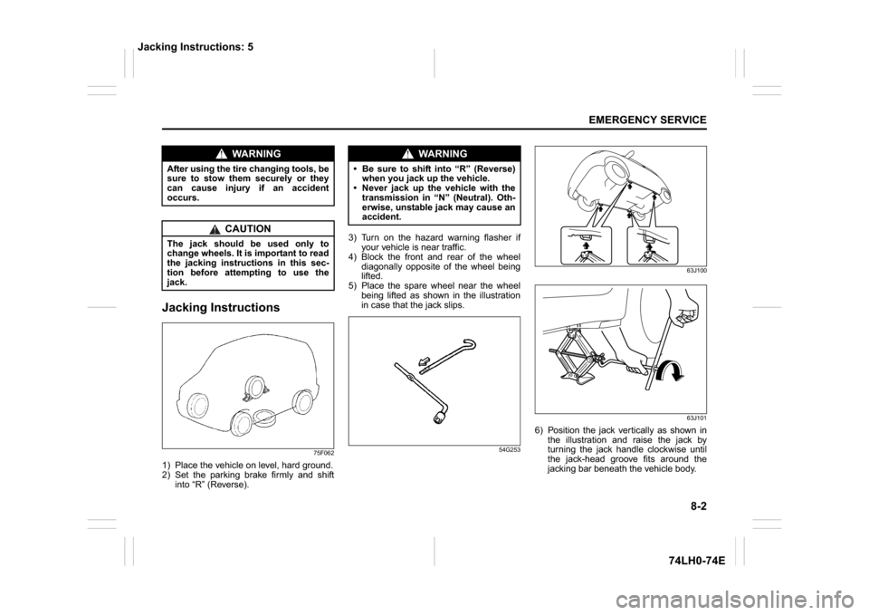
Jacking Instructions
75F062
1) Place the vehicle on level, hard ground.
2) Set the parking brake firmly and shift
into “R” (Reverse).3) Turn on the hazard warning flasher if
your vehicle is near traffic.
4) Block the front and rear of the wheel
diagonally opposite of the wheel being
lifted.
5) Place the spare wheel near the wheel
being lifted as shown in the illustration
in case that the jack slips.
54G25363J100
63J101
6) Position the jack vertically as shown in
the illustration and raise the jack by
turning the jack handle clockwise until
the jack-head groove fits around the
jacking bar beneath the vehicle body.
WA R N I N G
After using the tire changing tools, be
sure to stow them securely or they
can cause injury if an accident
occurs.
CAUTION
The jack should be used only to
change wheels. It is important to read
the jacking instructions in this sec-
tion before attempting to use the
jack.
WA R N I N G
Be sure to shift into “R” (Reverse)
when you jack up the vehicle.
Never jack up the vehicle with the
transmission in “N” (Neutral). Oth-
erwise, unstable jack may cause an
accident.
Jacking Instructions: 5