fuses SUZUKI SWIFT 2017 5.G Owners Manual
[x] Cancel search | Manufacturer: SUZUKI, Model Year: 2017, Model line: SWIFT, Model: SUZUKI SWIFT 2017 5.GPages: 336, PDF Size: 6.24 MB
Page 11 of 336
0-3
WARRANTY POLICYMaruti Suzuki India Limited (hereinafter called “Maruti Suzuki”),
warrants that each new Maruti Suzuki vehicle distributed in India
by Maruti Suzuki and sold by an authorised Maruti Suzuki dealer
will be free, under normal use and service, from any defects in
material and workmanship at the time of manufacture SUBJECT
TO THE FOLLOWING TERMS AND CONDITIONS:(1) Qualification:To qualify for this warranty the vehicle must be delivered by a
Maruti Suzuki authorised dealer and set-up, and serviced by a
Maruti Suzuki authorised dealer / service station.(2) Term:The term of the warranty shall be twenty-four (24) months or
40,000 kilometers (whichever occurs first) from the date of
Invoice to the first owner.(3) Maruti Suzuki Warranty Obligation:If any defect(s) should be found in a Maruti Suzuki vehicle within
the term stipulated above, Maruti Suzuki’s only obligation is to
repair or replace at its sole discretion any part shown to be defec-
tive, with a new part or the equivalent at no cost to the owner for
parts or labour, when Maruti Suzuki acknowledges that such a
defect is attributable to faulty material or workmanship at the time
of manufacture. The owner is responsible for any repair or replace-
ments which are not covered by this warranty.
(4) Limitation:This warranty shall not apply to:
(a) Normal maintenance service required other than the three free services, including without limitation, oil and fluid
changes, headlight aiming, fastener retightening, wheel bal-
ancing, wheel alignment and tyre rotation, cleaning of injec-
tors, adjustments of clutch and valve clearance.
(b) The replacement of normal wear parts including without lim- itation, bulbs, tyres and tubes, spark plugs, belts, hoses, fil-
ters, wiper blades, brushes, contact points, fuses, clutch
disc, brake shoes, brake pads, cable and all rubber parts
(except oil seal and glass run).
(c) Any vehicle which has been used for competition or racing.
(d) Any repairs or replacement required as a result of accidents or collision.
(e) Any defects caused by misuse, negligence, abnormal use or insufficient care.
(f) Any vehicle which has been modified or altered, including
without limitation, the installation of performance accesso-
ries.
(g) Any vehicle on which parts or accessories not approved by
Maruti Suzuki have been used.
(h) Any vehicle which has not been operated in accordance with the operating instructions in this Owner’s Manual and Ser-
vice Booklet.
(i) Any vehicle which has not received, during the warranty term, the service inspections prescribed in this Owner’s Manual
and Service Booklet.
(j) Any vehicle which has been assembled, disassembled, adjusted or repaired by other than an Maruti Suzuki autho-
rised dealer/service station.
(k) Any vehicle which has been used for purposes other than what it was designed for.
(l) Any damage or deterioration caused by industrial pollution and bird droppings.
Page 191 of 336
INSPECTION AND MAINTENANCE
INSPECTION AND MAINTENANCE
Maintenance Schedule ....................................................... 7-2
Periodic Maintenance Schedule ........................................ 7-2
Drive Belt ............................................................................. 7-6
Engine Oil and Filter ........................................................... 7-6
Engine Coolant .................................................................... 7-10
Air Cleaner ........................................................................... 7-11
Spark Plugs (Petrol Engine)................................................ 7-11
Gear Oil ................................................................................ 7-13
Clutch Pedal ........................................................................ 7-14
Fuel Filter (Diesel Engine) .................................................. 7-15
Brakes .................................................................................. 7-16
7
Steering ................................................................................ 7-17
Tires ...................................................................................... 7-18
Battery .................................................................................. 7-20
Fuses .................................................................................... 7-22
Bulb Replacement ............................................................... 7-24
Wiper Blades ....................................................................... 7-28
Windshield Washer Fluid ................................................... 7-30
Air Conditioning System .................................................... 7-30
74LH0-74E
Page 213 of 336
7-22
INSPECTION AND MAINTENANCE
74LH0-74E
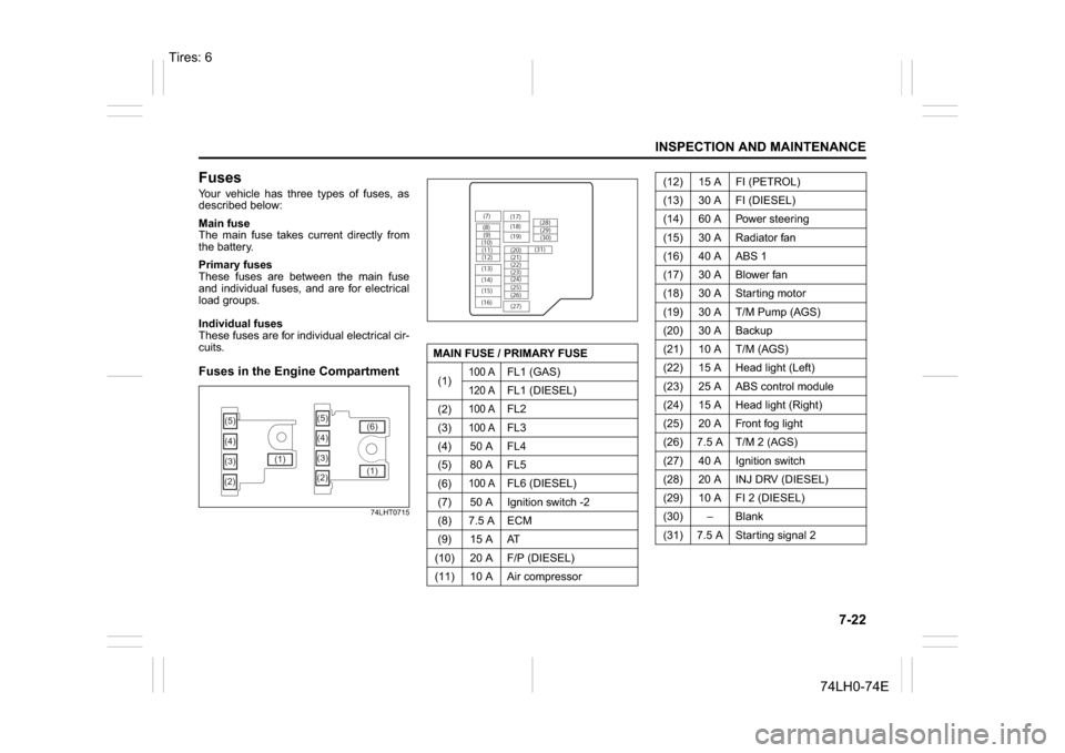
FusesYour vehicle has three types of fuses, as
described below:
Main fuse
The main fuse takes current directly from
the battery.
Primary fuses
These fuses are between the main fuse
and individual fuses, and are for electrical
load groups.
Individual fuses
These fuses are for individual electrical cir-
cuits.Fuses in the Engine Compartment
74LHT0715
(5)
(3) (4)
(2)(1)(5)
(4)
(3)
(2)(1) (6)
MAIN FUSE / PRIMARY FUSE
(1)
100 A
FL1 (GAS)
120 A
FL1 (DIESEL)
(2)
100 A
FL2
(3)
100 A
FL3
(4) 50 A FL4
(5) 80 A FL5
(6)
100 A
FL6 (DIESEL)
(7) 50 A Ignition switch -2
(8) 7.5 A ECM
(9) 15 A AT
(10) 20 A F/P (DIESEL)
(11) 10 A Air compressor
(7)
(8)(9)
(10)
(11)
(12)
(13)
(14)
(15)
(16)(17)
(18)
(20) (19)
(21)
(22)
(23)
(25) (24)
(26)
(27)(28)
(29)
(30)
(31)
(12) 15 A FI (PETROL)
(13) 30 A FI (DIESEL)
(14) 60 A Power steering
(15) 30 A Radiator fan
(16) 40 A ABS 1
(17) 30 A Blower fan
(18) 30 A Starting motor
(19) 30 A T/M Pump (AGS)
(20) 30 A Backup
(21) 10 A T/M (AGS)
(22) 15 A Head light (Left)
(23) 25 A ABS control module
(24) 15 A Head light (Right)
(25) 20 A Front fog light
(26) 7.5 A T/M 2 (AGS)
(27) 40 A Ignition switch
(28) 20 A INJ DRV (DIESEL)
(29) 10 A FI 2 (DIESEL)
(30)
Page 214 of 336
7-23INSPECTION AND MAINTENANCE
74LH0-74E
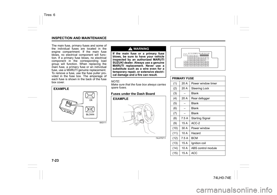
The main fuse, primary fuses and some of
the individual fuses are located in the
engine compartment. If the main fuse
blows, no electrical component will func-
tion. If a primary fuse blows, no electrical
component in the corresponding load
group will function. When replacing the
main fuse, a primary fuse or an individual
fuse, use a MARUTI genuine replacement.
To remove a fuse, use the fuse puller pro-
vided in the fuse box. The amperage of
each fuse is shown in the back of the fuse
box cover.
60G111
NOTE:
Make sure that the fuse box always carries
spare fuses.Fuses under the Dash Board
74LHT0711
EXAMPLE
BLOWNOK
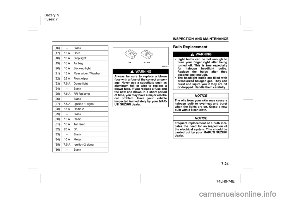
WA R N I N G
If the main fuse or a primary fuse
blows, be sure to have your vehicle
inspected by an authorized MARUTI
SUZUKI dealer. Always use a genuine
MARUTI replacement. Never use a
substitute such as a wire even for a
temporary repair, or extensive electri-
cal damage and a fire can result.EXAMPLE
PRIMARY FUSE
(1) 20 A Power window timer
(2) 20 A Steering Lock
(3) – Blank
(4) 20 A Rear defogger
(5) – Blank
(6) – Blank
(7) – Blank
(8) 7.5 A Starting Signal
(9) 15 A ACC-2
(10) 30 A Power window
(11) 10 A Hazard
(12) 7.5 A BCM
(13) 15 A Ignition coil
(14) 10 A ABS control module
(15) 15 A ACC
(3)
(12)(10)
(13)
(36) (1) (2) (4)
(5)(6)
(7) (8)(9)
(11) (14) (15)
(16) (17) (18) (19) (20) (21) (22)
(23) (24) (25) (26) (27) (28) (29)
(30) (31) (32) (33) (34) (35)
Tires: 6
Page 215 of 336
7-24
INSPECTION AND MAINTENANCE
74LH0-74E
81A283
Bulb Replacement
(16) – Blank
(17) 15 A Horn
(18) 10 A Stop light
(19) 10 A Air bag
(20) 10 A Back-up light
(21) 15 A Rear wiper / Washer
(22) 25 A Front wiper
(23) 7.5 A Dome light
(24) – Blank
(25) 7.5 A RR fog lamp
(26) – Blank
(27) 7.5 A Ignition-1 signal
(28) 15 A Radio 2
(29) – Blank
(30) 15 A Radio
(31) 10 A Tail lamp
(32) 20 A D/L
(33) – Blank
(34) 10 A Meter
(35) 7.5 A Ignition-2 signal
(36) – Blank
WA R N I N G
Always be sure to replace a blown
fuse with a fuse of the correct amper-
age. Never use a substitute such as
aluminum foil or wire to replace a
blown fuse. If you replace a fuse and
the new one blows in a short period
of time, you may have a major electri-
cal problem. Have your vehicle
inspected immediately by your MAR-
UTI SUZUKI dealer.
OK
BLOWN
WA R N I N G
Light bulbs can be hot enough to
burn your finger right after being
turned off. This is true especially
for halogen headlight bulbs.
Replace the bulbs after they
become cool enough.
The headlight bulbs are filled with
pressurized halogen gas. They can
burst and injure you if they are hit
or dropped. Handle them carefully.
NOTICE
The oils from your skin may cause a
halogen bulb to overheat and burst
when the lights are on. Grasp a new
bulb with a clean cloth.
NOTICE
Frequent replacement of a bulb indi-
cates the need for an inspection of
the electrical system. This should be
carried out by your MARUTI SUZUKI
dealer.
Battery: 9
Fuses: 7
Page 216 of 336
7-25INSPECTION AND MAINTENANCE
74LH0-74E
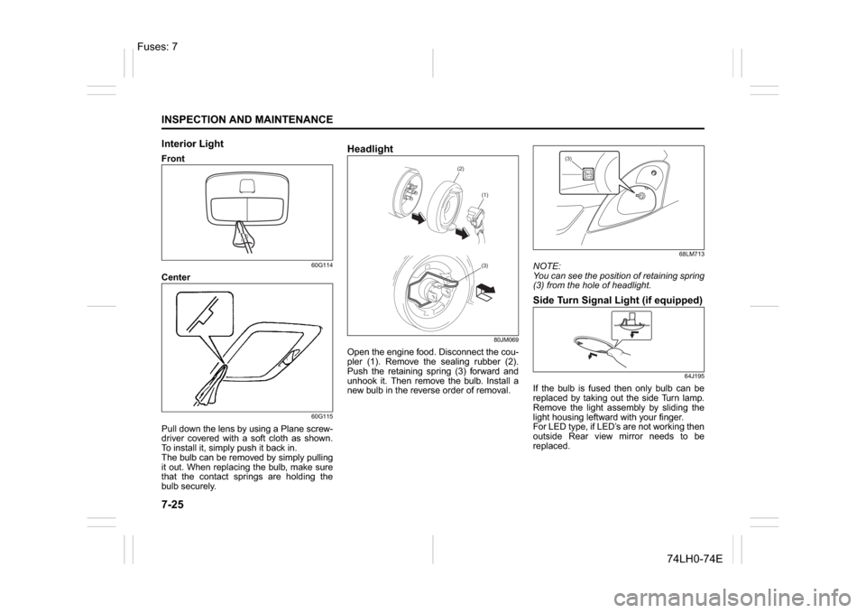
Interior LightFront
60G114
Center
60G115
Pull down the lens by using a Plane screw-
driver covered with a soft cloth as shown.
To install it, simply push it back in.
The bulb can be removed by simply pulling
it out. When replacing the bulb, make sure
that the contact springs are holding the
bulb securely.
Headlight
80JM069
Open the engine food. Disconnect the cou-
pler (1). Remove the sealing rubber (2).
Push the retaining spring (3) forward and
unhook it. Then remove the bulb. Install a
new bulb in the reverse order of removal.
68LM713
NOTE:
You can see the position of retaining spring
(3) from the hole of headlight.Side Turn Signal Light (if equipped)
64J195
If the bulb is fused then only bulb can be
replaced by taking out the side Turn lamp.
Remove the light assembly by sliding the
light housing leftward with your finger.
For LED type, if LED’s are not working then
outside Rear view mirror needs to be
replaced.
(2)
(1)(3)
(3)
Fuses: 7
Page 217 of 336
7-26
INSPECTION AND MAINTENANCE
74LH0-74E
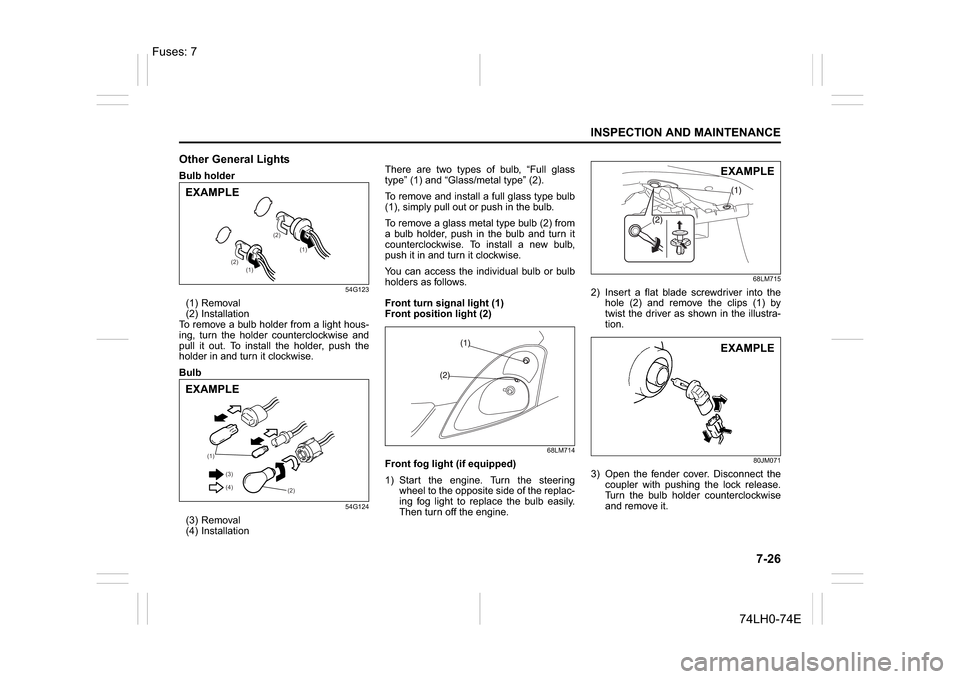
Other General LightsBulb holder
54G123
(1) Removal
(2) Installation
To remove a bulb holder from a light hous-
ing, turn the holder counterclockwise and
pull it out. To install the holder, push the
holder in and turn it clockwise.
Bulb
54G124
(3) Removal
(4) InstallationThere are two types of bulb, “Full glass
type” (1) and “Glass/metal type” (2).
To remove and install a full glass type bulb
(1), simply pull out or push in the bulb.
To remove a glass metal type bulb (2) from
a bulb holder, push in the bulb and turn it
counterclockwise. To install a new bulb,
push it in and turn it clockwise.
You can access the individual bulb or bulb
holders as follows.
Front turn signal light (1)
Front position light (2)
68LM714
Front fog light (if equipped)
1) Start the engine. Turn the steering
wheel to the opposite side of the replac-
ing fog light to replace the bulb easily.
Then turn off the engine.
68LM715
2) Insert a flat blade screwdriver into the
hole (2) and remove the clips (1) by
twist the driver as shown in the illustra-
tion.
80JM071
3) Open the fender cover. Disconnect the
coupler with pushing the lock release.
Turn the bulb holder counterclockwise
and remove it.
(1)
(1) (2)(2)
EXAMPLE
(1)
(2) (3)
(4)
EXAMPLE
EXAMPLEEXAMPLE
Fuses: 7
Page 229 of 336
8-6
EMERGENCY SERVICE
74LH0-74E
71LST0802
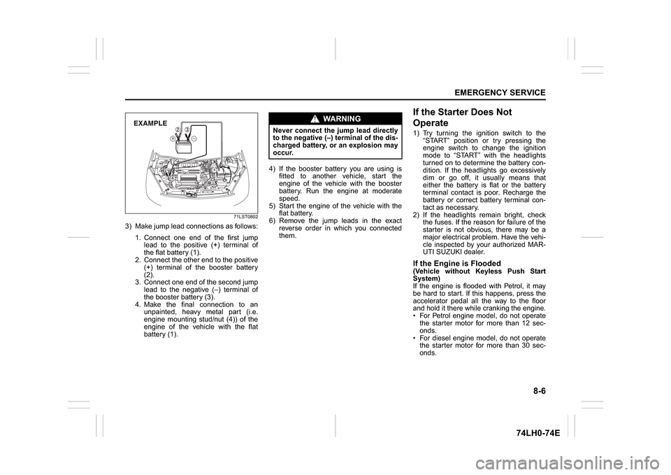
3) Make jump lead connections as follows:
1. Connect one end of the first jump
lead to the positive (+) terminal of
the flat battery (1).
2. Connect the other end to the positive
(+) terminal of the booster battery
(2).
3. Connect one end of the second jump
lead to the negative (–) terminal of
the booster battery (3).
4. Make the final connection to an
unpainted, heavy metal part (i.e.
engine mounting stud/nut (4)) of the
engine of the vehicle with the flat
battery (1).4) If the booster battery you are using is
fitted to another vehicle, start the
engine of the vehicle with the booster
battery. Run the engine at moderate
speed.
5) Start the engine of the vehicle with the
flat battery.
6) Remove the jump leads in the exact
reverse order in which you connected
them.
If the Starter Does Not
Operate1) Try turning the ignition switch to the
“START” position or try pressing the
engine switch to change the ignition
mode to “START” with the headlights
turned on to determine the battery con-
dition. If the headlights go excessively
dim or go off, it usually means that
either the battery is flat or the battery
terminal contact is poor. Recharge the
battery or correct battery terminal con-
tact as necessary.
2) If the headlights remain bright, check
the fuses. If the reason for failure of the
starter is not obvious, there may be a
major electrical problem. Have the vehi-
cle inspected by your authorized MAR-
UTI SUZUKI dealer.If the Engine is Flooded(Vehicle without Keyless Push Start
System)
If the engine is flooded with Petrol, it may
be hard to start. If this happens, press the
accelerator pedal all the way to the floor
and hold it there while cranking the engine.
For Petrol engine model, do not operate
the starter motor for more than 12 sec-
onds.
For diesel engine model, do not operate
the starter motor for more than 30 sec-
onds.
EXAMPLE
WA R N I N G
Never connect the jump lead directly
to the negative (–) terminal of the dis-
charged battery, or an explosion may
occur.
Page 230 of 336
8-7EMERGENCY SERVICE
74LH0-74E
(Vehicle with Keyless Push Start Sys-
tem)
If the engine is flooded with Petrol, it may
be hard to start. If this happens, press the
accelerator pedal all the way to the floor
and hold it there while cranking the engine.
For Petrol engine model, do not operate
the starter motor for more than 12 sec-
onds.
For diesel engine model, do not operate
the starter motor for more than 30 sec-
onds.
NOTE:
If the engine refuses to start, the starter
motor automatically stops after a certain
period of time. After the starter motor has
automatically stopped or there is anything
abnormal in the engine starting system,
the starter motor runs only while the
engine switch is held pressed.
If the Engine OverheatsThe engine could overheat temporarily
under severe driving conditions. If the
engine coolant temperature gauge indi-
cates overheating during driving:
1) Turn off the air conditioner, if equipped.
2) Take the vehicle to a safe place and
park.
3) Let the engine run at the normal idle
speed for a few minutes until the indica-
tor is within the normal, acceptable
temperature range between “H” and
“C”.
If the temperature indication does not
come down to within the normal, accept-
able range:
1) Turn off the engine and check that the
water pump belt and pulleys are not
damaged or slipping. If any abnormality
is found, correct it.
2) Check the coolant level in the reservoir.
If it is found to be lower than the “LOW”line, look for leaks at the radiator, water
pump, and radiator and heater hoses. If
you locate any leaks that may have
caused the overheating, do not run the
engine until these problems have been
corrected.
3) If you do not find a leak, carefully add
coolant to the reservoir and then the
radiator, if necessary. (Refer to “Engine
Coolant” in the “INSPECTION AND
MAINTENANCE” section.)
NOTE:
If your engine overheats and you are
unsure what to do, contact your MARUTI
SUZUKI dealer.
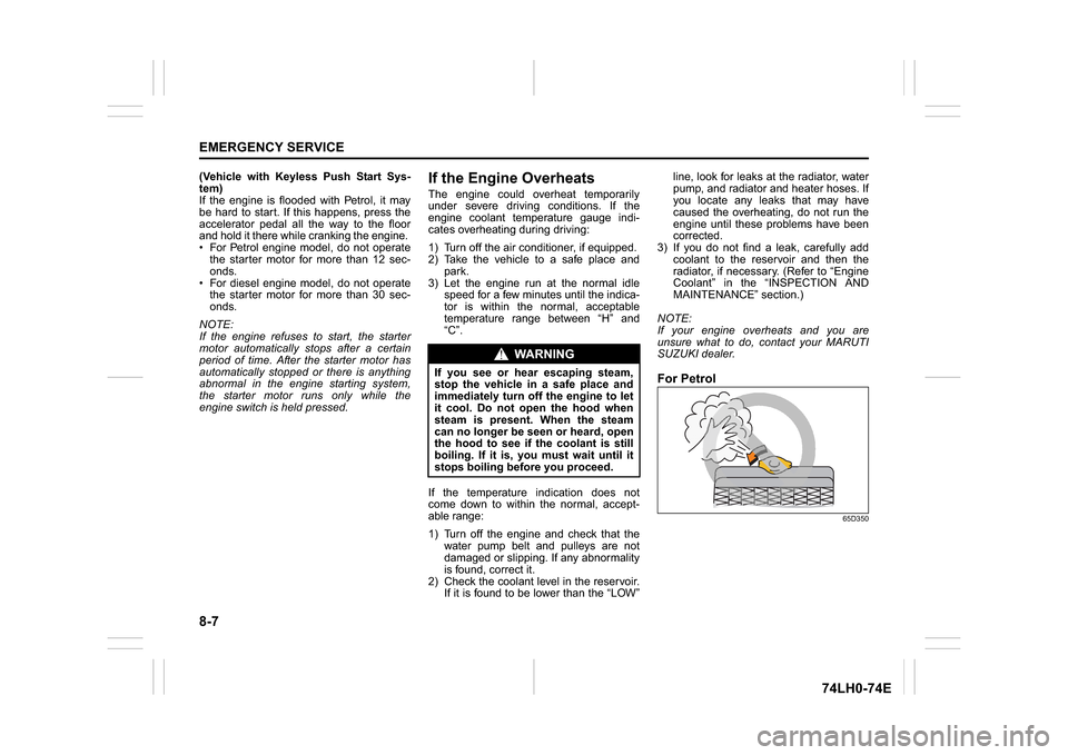
For Petrol
65D350
WA R N I N G
If you see or hear escaping steam,
stop the vehicle in a safe place and
immediately turn off the engine to let
it cool. Do not open the hood when
steam is present. When the steam
can no longer be seen or heard, open
the hood to see if the coolant is still
boiling. If it is, you must wait until it
stops boiling before you proceed.
Page 244 of 336
11-2SPECIFICATIONS
74LH0-74E
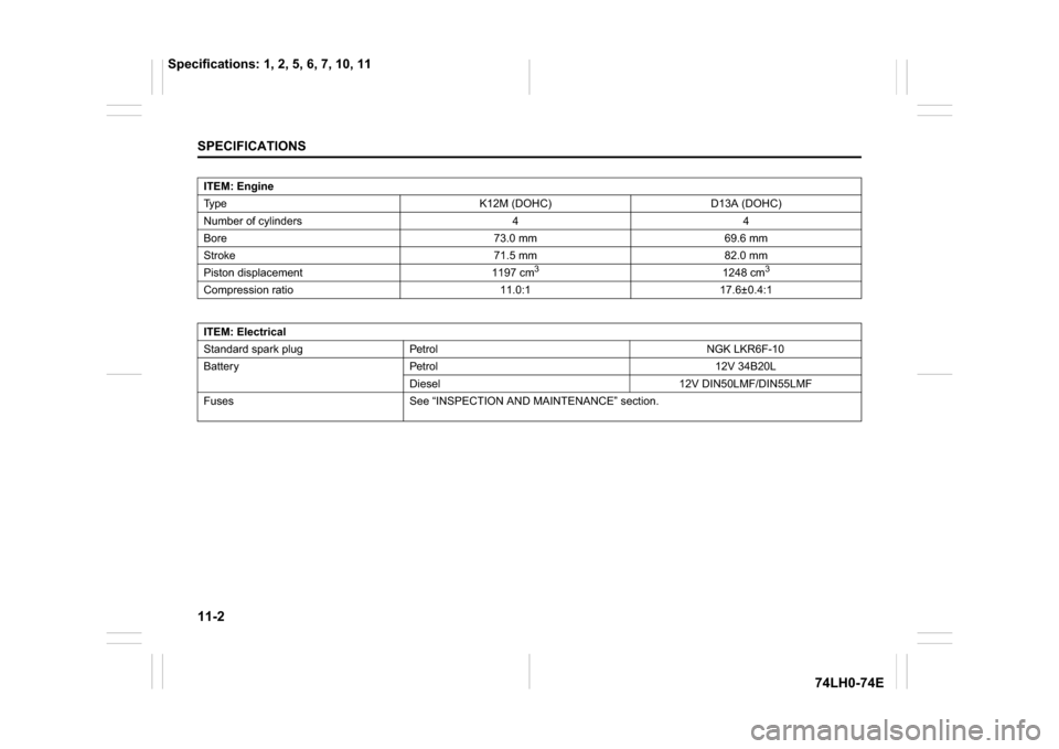
ITEM: Engine
Type K12M (DOHC) D13A (DOHC)
Number of cylinders 4 4
Bore 73.0 mm 69.6 mm
Stroke 71.5 mm 82.0 mm
Piston displacement 1197 cm
3
1248 cm
3
Compression ratio 11.0:1 17.6±0.4:1
ITEM: Electrical
Standard spark plug Petrol NGK LKR6F-10
Battery Petrol 12V 34B20L
Diesel 12V DIN50LMF/DIN55LMF
Fuses See “INSPECTION AND MAINTENANCE” section.
Specifications: 1, 2, 5, 6, 7, 10, 11