fuse type SUZUKI SX4 2006 1.G Service Workshop Manual
[x] Cancel search | Manufacturer: SUZUKI, Model Year: 2006, Model line: SX4, Model: SUZUKI SX4 2006 1.GPages: 1556, PDF Size: 37.31 MB
Page 51 of 1556
Downloaded from www.Manualslib.com manuals search engine Engine General Information and Diagnosis: 1A-1
Engine
Engine General Information and Diagnosis
Precautions
Precautions on Engine ServiceS6RW0D1100001
CAUTION!
The following information on engine service
should be noted carefully, as it is important in
preventing damage, and in contributing to
reliable engine performance.
• When raising or supporting engine for any reason, do
not use a jack under oil pan. Due to small clearance
between oil pan and oil pump strainer, jacking against
oil pan may cause it to be bent against strainer,
resulting in damaged oil pick-up unit.
• It should be kept in mind, while working on engine,
that 12-volt electrical system is capable of violent and
damaging short circuits.
When performing any work where electrical terminals
can be grounded, ground cable of the battery should
be disconnected at battery.
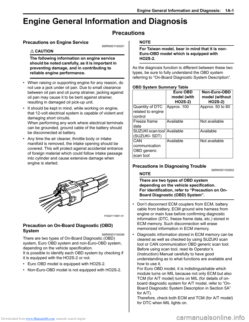
• Any time the air cleaner, throttle body or intake
manifold is removed, the intake opening should be
covered. This will protect against accidental entrance
of foreign material which could follow intake passage
into cylinder and cause extensive damage when
engine is started.
Precaution on On-Board Diagnostic (OBD)
System
S6RW0D1100006
There are two types of On-Board Diagnostic (OBD)
system, Euro OBD system and non-Euro-OBD system,
depending on the vehicle specification.
It is possible to identify each OBD system by checking if
it is equipped with the HO2S-2 or not.
• Euro OBD model is equipped with HO2S-2.
• Non-Euro-OBD model is not equipped with HO2S-2.
NOTE
For Taiwan model, bear in mind that it is non-
Euro-OBD model which is equipped with
HO2S-2.
As the diagnosis function is different between these two
types, be sure to fully understand the OBD system
referring to “On-Board Diagnostic System Description”.
OBD System Summary Table
Precautions in Diagnosing TroubleS6RW0D1100002
NOTE
There are two types of OBD system
depending on the vehicle specification.
For identification, refer to “Precaution on On-
Board Diagnostic (OBD) System”.
• Don’t disconnect ECM couplers from ECM, battery
cable from battery, ECM ground wire harness from
engine or main fuse before confirming diagnostic
information (DTC, freeze frame data, etc.) stored in
ECM memory. Such disconnection will erase
memorized information in ECM memory.
• Diagnostic information stored in ECM memory can be
cleared as well as checked by using SUZUKI scan
tool or CAN communication OBD generic scan tool.
Before using scan tool, read its Operator’s
(Instruction) Manual carefully to have good
understanding as to what functions are available and
how to use it.
For Euro OBD model, it is indistinguishable which
module turns on MIL because not only ECM but also
TCM (for A/T model) turns on MIL (for details of on-
board diagnostic system for A/T model, refer to “On-
Board Diagnostic System Description in Section 5A”
for A/T).
Therefore, check both ECM and TCM (for A/T model)
for DTC when MIL lights on.
IYSQ01110001-01
Euro OBD
model (with
HO2S-2)Non-Euro-OBD
model (without
HO2S-2)
Quantity of DTC
related to engine
controlApprox. 100 Approx. 50 to 80
Freeze frame
dataAvailable Not available
SUZUKI scan tool
(SUZUKI- SDT)Available Available
CAN
communication
OBD generic
scan toolAvailable Not available
Page 76 of 1556
Downloaded from www.Manualslib.com manuals search engine 1A-26 Engine General Information and Diagnosis:
• The MIL is turned on when the ECM and/or
TCM detect malfunction(s). Each ECM and
TCM stores diagnostic information as the
diagnostic trouble code (DTC) in its
memory and outputs the DTC to the scan
tool.
Therefore, check both of the ECM and TCM
for any DTC with the scan tool because the
DTC stored in ECM and TCM is not read
and displayed at a time. However, each of
the ECM and TCM needs not to be checked
with the generic scan tool because the
DTC stored in ECM and TCM is read and
displayed at a time.
1) Prepare CAN communication OBD generic scan tool
or SUZUKI scan tool.
Special tool
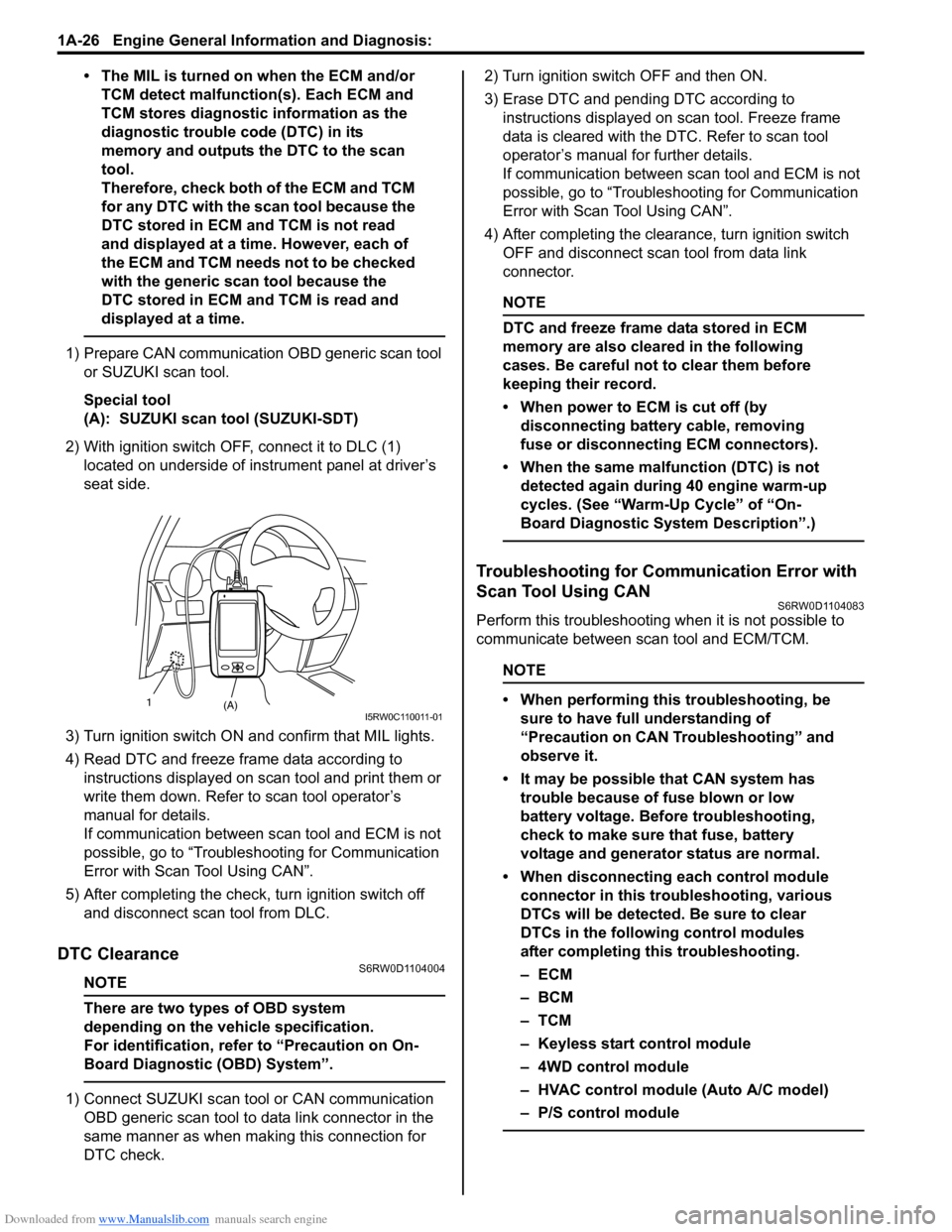
(A): SUZUKI scan tool (SUZUKI-SDT)
2) With ignition switch OFF, connect it to DLC (1)
located on underside of instrument panel at driver’s
seat side.
3) Turn ignition switch ON and confirm that MIL lights.
4) Read DTC and freeze frame data according to
instructions displayed on scan tool and print them or
write them down. Refer to scan tool operator’s
manual for details.
If communication between scan tool and ECM is not
possible, go to “Troubleshooting for Communication
Error with Scan Tool Using CAN”.
5) After completing the check, turn ignition switch off
and disconnect scan tool from DLC.
DTC ClearanceS6RW0D1104004
NOTE
There are two types of OBD system
depending on the vehicle specification.
For identification, refer to “Precaution on On-
Board Diagnostic (OBD) System”.
1) Connect SUZUKI scan tool or CAN communication
OBD generic scan tool to data link connector in the
same manner as when making this connection for
DTC check.2) Turn ignition switch OFF and then ON.
3) Erase DTC and pending DTC according to
instructions displayed on scan tool. Freeze frame
data is cleared with the DTC. Refer to scan tool
operator’s manual for further details.
If communication between scan tool and ECM is not
possible, go to “Troubleshooting for Communication
Error with Scan Tool Using CAN”.
4) After completing the clearance, turn ignition switch
OFF and disconnect scan tool from data link
connector.
NOTE
DTC and freeze frame data stored in ECM
memory are also cleared in the following
cases. Be careful not to clear them before
keeping their record.
• When power to ECM is cut off (by
disconnecting battery cable, removing
fuse or disconnecting ECM connectors).
• When the same malfunction (DTC) is not
detected again during 40 engine warm-up
cycles. (See “Warm-Up Cycle” of “On-
Board Diagnostic System Description”.)
Troubleshooting for Communication Error with
Scan Tool Using CAN
S6RW0D1104083
Perform this troubleshooting when it is not possible to
communicate between scan tool and ECM/TCM.
NOTE
• When performing this troubleshooting, be
sure to have full understanding of
“Precaution on CAN Troubleshooting” and
observe it.
• It may be possible that CAN system has
trouble because of fuse blown or low
battery voltage. Before troubleshooting,
check to make sure that fuse, battery
voltage and generator status are normal.
• When disconnecting each control module
connector in this troubleshooting, various
DTCs will be detected. Be sure to clear
DTCs in the following control modules
after completing this troubleshooting.
–ECM
–BCM
–TCM
– Keyless start control module
– 4WD control module
– HVAC control module (Auto A/C model)
– P/S control module
(A) 1I5RW0C110011-01
Page 384 of 1556
Downloaded from www.Manualslib.com manuals search engine 1G-7 Fuel System:
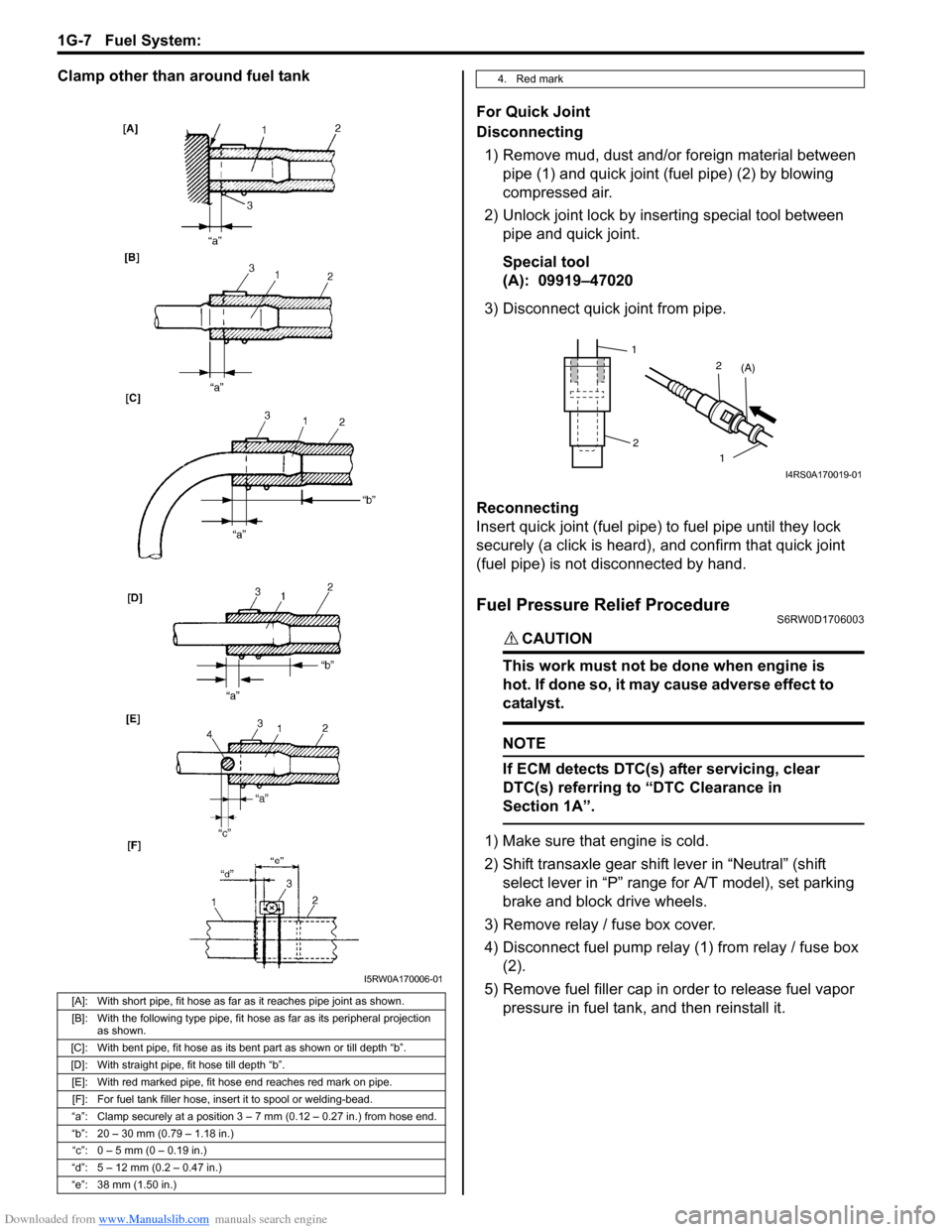
Clamp other than around fuel tank
For Quick Joint
Disconnecting
1) Remove mud, dust and/or foreign material between
pipe (1) and quick joint (fuel pipe) (2) by blowing
compressed air.
2) Unlock joint lock by inserting special tool between
pipe and quick joint.
Special tool
(A): 09919–47020
3) Disconnect quick joint from pipe.
Reconnecting
Insert quick joint (fuel pipe) to fuel pipe until they lock
securely (a click is heard), and confirm that quick joint
(fuel pipe) is not disconnected by hand.
Fuel Pressure Relief ProcedureS6RW0D1706003
CAUTION!
This work must not be done when engine is
hot. If done so, it may cause adverse effect to
catalyst.
NOTE
If ECM detects DTC(s) after servicing, clear
DTC(s) referring to “DTC Clearance in
Section 1A”.
1) Make sure that engine is cold.
2) Shift transaxle gear shift lever in “Neutral” (shift
select lever in “P” range for A/T model), set parking
brake and block drive wheels.
3) Remove relay / fuse box cover.
4) Disconnect fuel pump relay (1) from relay / fuse box
(2).
5) Remove fuel filler cap in order to release fuel vapor
pressure in fuel tank, and then reinstall it.
[A]: With short pipe, fit hose as far as it reaches pipe joint as shown.
[B]: With the following type pipe, fit hose as far as its peripheral projection
as shown.
[C]: With bent pipe, fit hose as its bent part as shown or till depth “b”.
[D]: With straight pipe, fit hose till depth “b”.
[E]: With red marked pipe, fit hose end reaches red mark on pipe.
[F]: For fuel tank filler hose, insert it to spool or welding-bead.
“a”: Clamp securely at a position 3 – 7 mm (0.12 – 0.27 in.) from hose end.
“b”: 20 – 30 mm (0.79 – 1.18 in.)
“c”: 0 – 5 mm (0 – 0.19 in.)
“d”: 5 – 12 mm (0.2 – 0.47 in.)
“e”: 38 mm (1.50 in.)
I5RW0A170006-01
4. Red mark
1
2
1 2
(A)
I4RS0A170019-01
Page 399 of 1556
Downloaded from www.Manualslib.com manuals search engine Ignition System: 1H-4
Diagnostic Information and Procedures
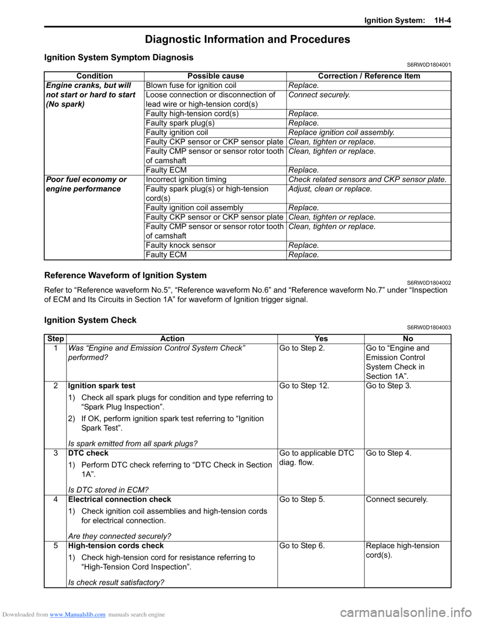
Ignition System Symptom DiagnosisS6RW0D1804001
Reference Waveform of Ignition SystemS6RW0D1804002
Refer to “Reference waveform No.5”, “Reference waveform No.6” and “Reference waveform No.7” under “Inspection
of ECM and Its Circuits in Section 1A” for waveform of Ignition trigger signal.
Ignition System CheckS6RW0D1804003
Condition Possible cause Correction / Reference Item
Engine cranks, but will
not start or hard to start
(No spark)Blown fuse for ignition coilReplace.
Loose connection or disconnection of
lead wire or high-tension cord(s)Connect securely.
Faulty high-tension cord(s)Replace.
Faulty spark plug(s)Replace.
Faulty ignition coilReplace ignition coil assembly.
Faulty CKP sensor or CKP sensor plateClean, tighten or replace.
Faulty CMP sensor or sensor rotor tooth
of camshaftClean, tighten or replace.
Faulty ECMReplace.
Poor fuel economy or
engine performanceIncorrect ignition timingCheck related sensors and CKP sensor plate.
Faulty spark plug(s) or high-tension
cord(s)Adjust, clean or replace.
Faulty ignition coil assemblyReplace.
Faulty CKP sensor or CKP sensor plateClean, tighten or replace.
Faulty CMP sensor or sensor rotor tooth
of camshaftClean, tighten or replace.
Faulty knock sensorReplace.
Faulty ECMReplace.
Step Action Yes No
1Was “Engine and Emission Control System Check”
performed?Go to Step 2. Go to “Engine and
Emission Control
System Check in
Section 1A”.
2Ignition spark test
1) Check all spark plugs for condition and type referring to
“Spark Plug Inspection”.
2) If OK, perform ignition spark test referring to “Ignition
Spar k Tes t”.
Is spark emitted from all spark plugs?Go to Step 12. Go to Step 3.
3DTC check
1) Perform DTC check referring to “DTC Check in Section
1A”.
Is DTC stored in ECM?Go to applicable DTC
diag. flow.Go to Step 4.
4Electrical connection check
1) Check ignition coil assemblies and high-tension cords
for electrical connection.
Are they connected securely?Go to Step 5. Connect securely.
5High-tension cords check
1) Check high-tension cord for resistance referring to
“High-Tension Cord Inspection”.
Is check result satisfactory?Go to Step 6. Replace high-tension
cord(s).
Page 945 of 1556
![SUZUKI SX4 2006 1.G Service Workshop Manual Downloaded from www.Manualslib.com manuals search engine Air Conditioning System: Manual Type 7B-5
A/C System Wiring DiagramS6RW0D7212002
[A]
7
WHT
GRN5YELBLK
3
G154-3
G154-4
G154-7
G154-8
G154-10
G15 SUZUKI SX4 2006 1.G Service Workshop Manual Downloaded from www.Manualslib.com manuals search engine Air Conditioning System: Manual Type 7B-5
A/C System Wiring DiagramS6RW0D7212002
[A]
7
WHT
GRN5YELBLK
3
G154-3
G154-4
G154-7
G154-8
G154-10
G15](/img/20/7612/w960_7612-944.png)
Downloaded from www.Manualslib.com manuals search engine Air Conditioning System: Manual Type 7B-5
A/C System Wiring DiagramS6RW0D7212002
[A]
7
WHT
GRN5YELBLK
3
G154-3
G154-4
G154-7
G154-8
G154-10
G154-13
G154-5
G154-6
G155-5
G155-2
G155-3
G155-7
G155-6
G155-1
G154-9
G154-14
BLK/WHT
YEL
BLU/WHT
RED
BRN
GRN/WHT
RED/BLK
RED
GRN
GRN/YEL
RED/YEL
RED/BLU
20
21
23 22
BLK/RED
6 2
MBLK/WHTBLK/YEL
M
11
4RED/YEL 1
E01-49
12
E01-16
GRY 13
12V
BLU/WHTE01-3510
E01-48
18
19RED/BLK
BLK/RED
BLK/RED
BRN/WHTE01-60
E01-1
E01-29BLK/WHT
M
BLU/YELBLK/YEL
5V5V 5V
WHT/BLK
9
ORN
14E01-36
C01-12C01-14GRY/REDRED/BLU
E01-41
RED/BLK
RED
WHT
8
BLK
BLK/ORN
BLU IG1
IG2
5V
17
28
29
31
2726 2524
16
16
30
34
33E01-4 E01-19WHTRED
C01-50C01-49WHTRED
32
LT GRN
C01-57
C01-2415
GRY/BLU5V
I6RW0C721002-01
[A]: Illumination control model 9. A/C refrigerant pressure
sensor18. Condenser cooling fan relay 27. Illumination light
1. Ignition switch 10. ECM 19. Condenser cooling fan motor 28. Rear defogger relay
2. Blower motor 11. Air intake control actuator 20. Blower speed selector 29. Rear defogger
3. HVAC control unit 12. Compressor relay 21. A/C switch 30. Main relay
4. Lighting switch 13. Compressor 22. Air intake selector 31. Tail light
5. Blower motor relay 14. Evaporator temperature
sensor23. Rear defogger switch 32. TCM
6. Blower motor resistor 15. ECT sensor 24. “A/C” indicator light 33. To other control module and DLC
7. Junction block assembly 16. To BCM 25. “REC” indicator light 34. ABS control module
8. BCM 17. Main fuse box 26. Rear defogger indicator
Page 953 of 1556
Downloaded from www.Manualslib.com manuals search engine Air Conditioning System: Manual Type 7B-13
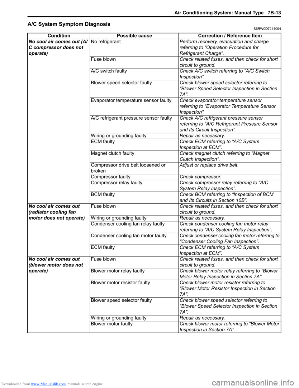
A/C System Symptom DiagnosisS6RW0D7214004
Condition Possible cause Correction / Reference Item
No cool air comes out (A/
C compressor does not
operate)No refrigerantPerform recovery, evacuation and charge
referring to “Operation Procedure for
Refrigerant Charge”.
Fuse blownCheck related fuses, and then check for short
circuit to ground.
A/C switch faultyCheck A/C switch referring to “A/C Switch
Inspection”.
Blower speed selector faultyCheck blower speed selector referring to
“Blower Speed Selector Inspection in Section
7A”.
Evaporator temperature sensor faultyCheck evaporator temperature sensor
referring to “Evaporator Temperature Sensor
Inspection”.
A/C refrigerant pressure sensor faultyCheck A/C refrigerant pressure sensor
referring to “A/C Refrigerant Pressure Sensor
and Its Circuit Inspection”.
Wiring or grounding faultyRepair as necessary.
ECM faultyCheck ECM referring to “A/C System
Inspection at ECM”.
Magnet clutch faultyCheck magnet clutch referring to “Magnet
Clutch Inspection”.
Compressor drive belt loosened or
brokenAdjust or replace drive belt.
Compressor faultyCheck compressor.
Compressor relay faultyCheck compressor relay referring to “A/C
System Relay Inspection”.
BCM faultyCheck BCM referring to “Inspection of BCM
and Its Circuits in Section 10B”.
No cool air comes out
(radiator cooling fan
motor does not operate)Fuse blownCheck related fuses, and then check for short
circuit to ground.
Wiring or grounding faultyRepair as necessary.
Condenser cooling fan relay faultyCheck condenser cooling fan motor relay
referring to “A/C System Relay Inspection”.
Condenser cooling fan motor faultyCheck condenser cooling fan motor referring to
“Condenser Cooling Fan Inspection”.
ECM faultyCheck ECM referring to “A/C System
Inspection at ECM”.
No cool air comes out
(blower motor does not
operate)Fuse blownCheck related fuses, and then check for short
circuit to ground.
Blower motor relay faultyCheck blower motor relay referring to “Blower
Motor Relay Inspection in Section 7A”.
Blower motor resistor faultyCheck blower motor resistor referring to
“Blower Motor Resistor Inspection in Section
7A”.
Blower speed selector faultyCheck blower speed selector referring to
“Blower Speed Selector Inspection in Section
7A”.
Wiring or grounding faultyRepair as necessary.
Blower motor faultyCheck blower motor referring to “Blower Motor
Inspection in Section 7A”.
Page 970 of 1556

Downloaded from www.Manualslib.com manuals search engine 7B-30 Air Conditioning System: Manual Type
A/C System Relay InspectionS6RW0D7216017
NOTE
Do not use blue relay for the substitute of
white relay because internal durability of a
blue relay is different from the durability of a
white relay.
1) Disconnect negative (–) cable from battery.
2) Remove compressor relay (1) or condenser cooling
fan relay (2) from main fuse box (3).
3) Check that there is no continuity between terminal
“c” and “d”. If there is continuity, replace relay.
4) Connect battery positive (+) terminal to terminal “b”
of relay and battery negative (–) terminal to terminal
“a” of relay, and then check continuity between
terminal “c” and “d”. If there is no continuity, replace
relay.
Compressor Drive Belt Inspection and
Adjustment
S6RW0D7216018
Inspection
• Check compressor drive belt (1) for wear, crack,
deformation and cleanliness. If any defect is found,
replace the belt with new one referring to
“Compressor Drive Belt Removal and Installation”.
• Check compressor drive belt tension by measuring
how much it deflects when pushed intermediate point
between magnet clutch pulley (6) and crankshaft
pulley (3) with about 100 N (10 kg) force after rotating
crankshaft pulley 360°. If belt tension is out of
specification, adjust belt tension referring to
“Adjustment”.
Compressor drive belt tension
“a”
: 7 – 8 mm (0.28 – 0.31 in.)
NOTE
When replacing drive belt, adjust drive belt
tension to the following specifications.
New compressor drive belt tension “a”
: 6 – 7 mm (0.24 – 0.28 in.)
Adjustment
1) Loosen tension pulley nut (4).
2) Adjust belt tension by tighten or loosen tension
pulley adjusting bolt (5).
3) Tighten tension pulley nut.
4) Rotate the crankshaft pulley 360°, and then recheck
belt tension.
3
1
2
“a”
“b”“c”
“d”
I5RW0B721023-01
2. Tension pulley
I5RW0A721033-01
Page 978 of 1556
Downloaded from www.Manualslib.com manuals search engine 7B-38 Air Conditioning System: Automatic Type
Automatic Type
Precautions
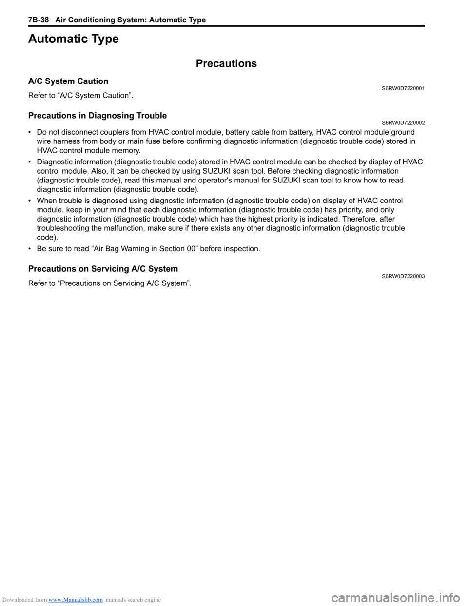
A/C System CautionS6RW0D7220001
Refer to “A/C System Caution”.
Precautions in Diagnosing TroubleS6RW0D7220002
• Do not disconnect couplers from HVAC control module, battery cable from battery, HVAC control module ground
wire harness from body or main fuse before confirming diagnostic information (diagnostic trouble code) stored in
HVAC control module memory.
• Diagnostic information (diagnostic trouble code) stored in HVAC control module can be checked by display of HVAC
control module. Also, it can be checked by using SUZUKI scan tool. Before checking diagnostic information
(diagnostic trouble code), read this manual and operator's manual for SUZUKI scan tool to know how to read
diagnostic information (diagnostic trouble code).
• When trouble is diagnosed using diagnostic information (diagnostic trouble code) on display of HVAC control
module, keep in your mind that each diagnostic information (diagnostic trouble code) has priority, and only
diagnostic information (diagnostic trouble code) which has the highest priority is indicated. Therefore, after
troubleshooting the malfunction, make sure if there exists any other diagnostic information (diagnostic trouble
code).
• Be sure to read “Air Bag Warning in Section 00” before inspection.
Precautions on Servicing A/C SystemS6RW0D7220003
Refer to “Precautions on Servicing A/C System”.
Page 983 of 1556
Downloaded from www.Manualslib.com manuals search engine Air Conditioning System: Automatic Type 7B-43
Component Location
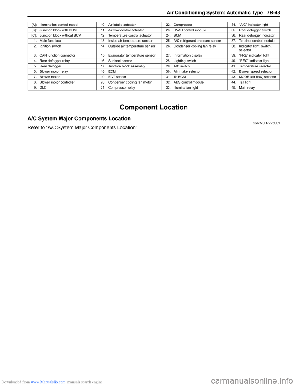
A/C System Major Components LocationS6RW0D7223001
Refer to “A/C System Major Components Location”.
[A]: Illumination control model 10. Air intake actuator 22. Compressor 34. “A/C” indicator light
[B]: Junction block with BCM 11. Air flow control actuator 23. HVAC control module 35. Rear defogger switch
[C]: Junction block without BCM 12. Temperature control actuator 24. BCM 36. Rear defogger indicator
1. Main fuse box 13. Inside air temperature sensor 25. A/C refrigerant pressure sensor 37. To other control module
2. Ignition switch 14. Outside air temperature sensor 26. Condenser cooling fan relay 38. Indicator light, switch,
selector
3. CAN junction connector 15. Evaporator temperature sensor 27. Information display 39. “FRE” indicator light
4. Rear defogger relay 16. Sunload sensor 28. Lighting switch 40. “REC” indicator light
5. Rear defogger 17. Junction block assembly 29. A/C switch 41. Temperature selector
6. Blower motor relay 18. ECM 30. Air intake selector 42. Blower speed selector
7. Blower motor 19. ECT sensor 31. To BCM 43. MODE (air flow) selector
8. Blower motor controller 20. Condenser cooling fan motor 32. ABS control module 44. Tail light
9. DLC 21. Compressor relay 33. Illumination light 45. Main relay
Page 987 of 1556
Downloaded from www.Manualslib.com manuals search engine Air Conditioning System: Automatic Type 7B-47
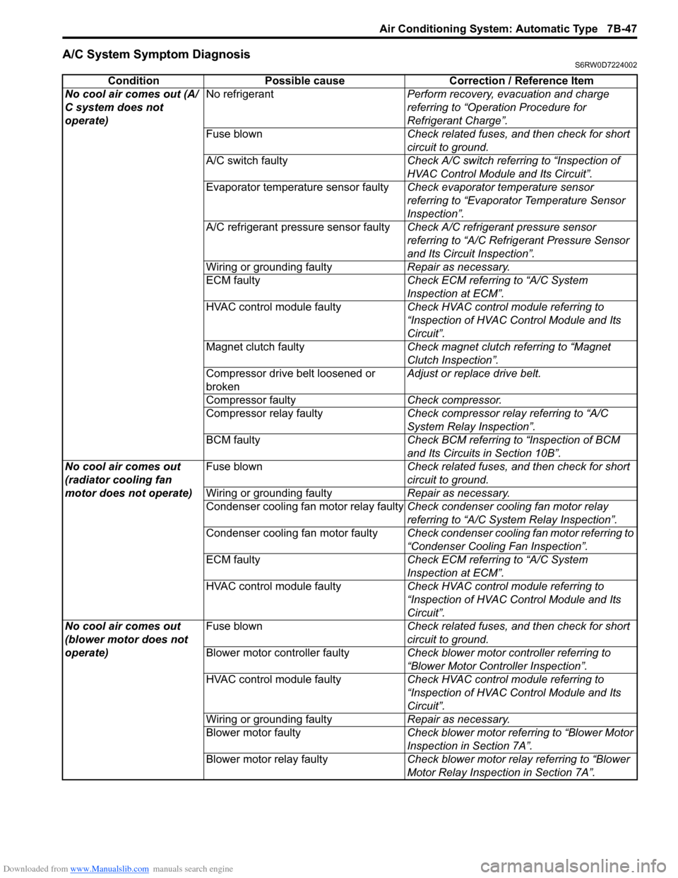
A/C System Symptom DiagnosisS6RW0D7224002
Condition Possible cause Correction / Reference Item
No cool air comes out (A/
C system does not
operate)No refrigerantPerform recovery, evacuation and charge
referring to “Operation Procedure for
Refrigerant Charge”.
Fuse blownCheck related fuses, and then check for short
circuit to ground.
A/C switch faultyCheck A/C switch referring to “Inspection of
HVAC Control Module and Its Circuit”.
Evaporator temperature sensor faultyCheck evaporator temperature sensor
referring to “Evaporator Temperature Sensor
Inspection”.
A/C refrigerant pressure sensor faultyCheck A/C refrigerant pressure sensor
referring to “A/C Refrigerant Pressure Sensor
and Its Circuit Inspection”.
Wiring or grounding faultyRepair as necessary.
ECM faultyCheck ECM referring to “A/C System
Inspection at ECM”.
HVAC control module faultyCheck HVAC control module referring to
“Inspection of HVAC Control Module and Its
Circuit”.
Magnet clutch faultyCheck magnet clutch referring to “Magnet
Clutch Inspection”.
Compressor drive belt loosened or
brokenAdjust or replace drive belt.
Compressor faultyCheck compressor.
Compressor relay faultyCheck compressor relay referring to “A/C
System Relay Inspection”.
BCM faultyCheck BCM referring to “Inspection of BCM
and Its Circuits in Section 10B”.
No cool air comes out
(radiator cooling fan
motor does not operate)Fuse blownCheck related fuses, and then check for short
circuit to ground.
Wiring or grounding faultyRepair as necessary.
Condenser cooling fan motor relay faultyCheck condenser cooling fan motor relay
referring to “A/C System Relay Inspection”.
Condenser cooling fan motor faultyCheck condenser cooling fan motor referring to
“Condenser Cooling Fan Inspection”.
ECM faultyCheck ECM referring to “A/C System
Inspection at ECM”.
HVAC control module faultyCheck HVAC control module referring to
“Inspection of HVAC Control Module and Its
Circuit”.
No cool air comes out
(blower motor does not
operate)Fuse blownCheck related fuses, and then check for short
circuit to ground.
Blower motor controller faultyCheck blower motor controller referring to
“Blower Motor Controller Inspection”.
HVAC control module faultyCheck HVAC control module referring to
“Inspection of HVAC Control Module and Its
Circuit”.
Wiring or grounding faultyRepair as necessary.
Blower motor faultyCheck blower motor referring to “Blower Motor
Inspection in Section 7A”.
Blower motor relay faultyCheck blower motor relay referring to “Blower
Motor Relay Inspection in Section 7A”.