fuse type SUZUKI SX4 2006 1.G Service User Guide
[x] Cancel search | Manufacturer: SUZUKI, Model Year: 2006, Model line: SX4, Model: SUZUKI SX4 2006 1.GPages: 1556, PDF Size: 37.31 MB
Page 997 of 1556
Downloaded from www.Manualslib.com manuals search engine Air Conditioning System: Automatic Type 7B-57
SUN LOAD (W/m2): This parameter indicates the
amount of sunlight detected by sunload sensor.
MODE CONT SWITCH (Air flow selector position,
AUTO, FACE, B/L, FOOT, D/F, DEF): This
parameter indicates the selected position of air flow
selector.
FAN CONT SWITCH (Blower speed selector, AUTO,
OFF, 1st – 8th): This parameter indicates the
selected position of blower speed selector.
FAN DESIRE VOLT (Fan desired voltage, V): This
parameter indicates the consumption voltage of
blower motor.
AIR MIX POS SENSOR (Temperature control
actuator position sensor, V): This parameter
indicates the input signal from position sensor in
temperature control actuator.
MODE POS SENSOR (Air flow control actuator
position sensor, V): This parameter indicates the
input signal from position sensor in air flow control
actuator.
A/C CONT SIG (A/C control signal, ON, OFF): This
parameter indicates the state of A/C switch.BLOWER LOAD SIG (Blower fan load signal, ON,
OFF): ON: Position of blower speed selector is 1st
position or more.
OFF: Position of blower speed selector is OFF
position.
AIR INTAKE MODE (Air intake selector position,
AUTO, FRE, REC): This parameter indicates the
selected position of air intake selector.
REFRIGERANT PRESSURE (A/C refrigerant absolute
pressure, kPa): This parameter indicates the A/C
refrigerant absolute pressure calculated by ECM
A/C COMP CLUCH (A/C compressor magnet clutch,
ON, OFF): This parameter indicates the state of the
A/C compressor magnet clutch.
VEHICLE SPEED (km/h, mph): This parameter
indicates the vehicle speed calculated by ECM.
ENGINE TYPE (Engine type signal, J20, M16 or
M15): This parameter indicates the engine type
signal transmitted by ECM.
METER SPEC (Combination meter spec signal, EU,
UK, US, Canada, DOM): This parameter indicates
the combination meter spec signal transmitted by
combination meter.
Visual InspectionS6RW0D7224009
Check visually the following parts and systems.
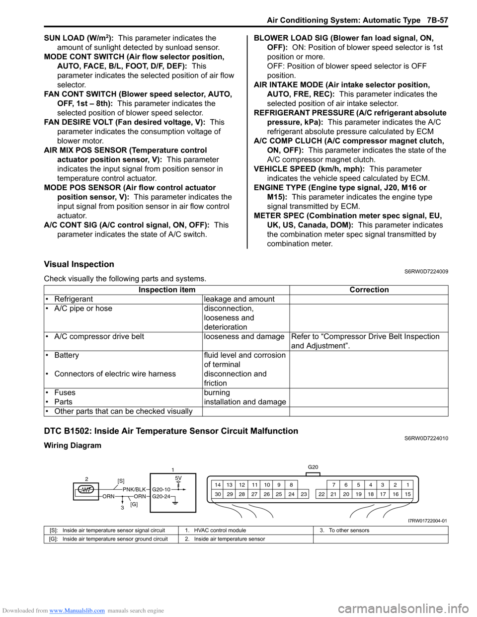
DTC B1502: Inside Air Temperature Sensor Circuit MalfunctionS6RW0D7224010
Wiring DiagramInspection item Correction
• Refrigerant leakage and amount
• A/C pipe or hose disconnection,
looseness and
deterioration
• A/C compressor drive belt looseness and damageRefer to “Compressor Drive Belt Inspection
and Adjustment”.
• Battery fluid level and corrosion
of terminal
• Connectors of electric wire harness disconnection and
friction
• Fuses burning
• Parts installation and damage
• Other parts that can be checked visually
5V
G20
1 2 3 4 5 6 7 8 9 10 11 12 13 14
15 16 17 18 19 20 21 24 23 22 25 26 27 28 29 30
ORNORNPNK/BLKG20-10
21
3 [S]
[G]
G20-24
I7RW01722004-01
[S]: Inside air temperature sensor signal circuit 1. HVAC control module 3. To other sensors
[G]: Inside air temperature sensor ground circuit 2. Inside air temperature sensor
Page 1009 of 1556

Downloaded from www.Manualslib.com manuals search engine Air Conditioning System: Automatic Type 7B-69
DTC B1541: Back-Up Power Supply Circuit MalfunctionS6RW0D7224018
Wiring Diagram
DTC Detecting Condition and Trouble Area
NOTE
When checking DTC after connecting battery cable, be sure to turn ignition switch from OFF to ON and
from ON to OFF at least once, or DTC B1541 will be detected.
DTC Troubleshooting
12V5V
WHTG20-7 2
31G201 2 3 4 5 6 7 8 9 10 11 12 13 14
15 16 17 18 19 20 21 24 23 22 25 26 27 28 29 30WHT/RED [B]
I7RW01722011-01
[B]: Back-up power supply circuit 2. Main fuse
1. HVAC control module 3. Circuit fuse
DTC Detecting Condition Trouble Area
• Back-up power supply voltage is lower than specified value continuously.
• When connect battery with vehicle and then, turn ignition switch to ON
position for first time.• Battery voltage supply circuit
• HVAC control module
Step Action Yes No
1Was “Air Conditioning System Check” performed?Go to Step 2. Go to “Air Conditioning
System Check”.
2DTC check
1) Turn ignition switch to ON position for 20 sec. or more.
2) Ignition switch turned OFF and connect scan tool to
DLC.
3) Turn ON ignition switch and check DTC.
Is there DTC B1541?Go to Step 3. Intermittent trouble.
Check for intermittent
referring to “Intermittent
and Poor Connection
Inspection in Section
00”.
3Battery voltage supply circuit check
1) Disconnect connector from HVAC control module with
ignition switch turned OFF.
2) Check for proper connection to back-up power supply
circuit terminal of HVAC control module connector.
3) If OK, measure voltage between back-up power supply
circuit terminal of HVAC control module connector and
vehicle body ground.
Is voltage 10 – 14 V?Substitute a known-
good HVAC control
module and recheck.Back-up power supply
circuit is open or
shorted to ground.
Page 1010 of 1556

Downloaded from www.Manualslib.com manuals search engine 7B-70 Air Conditioning System: Automatic Type
DTC B1546: A/C Refrigerant Pressure MalfunctionS6RW0D7224019
DTC Detecting Condition and Trouble Area
DTC Troubleshooting
DTC B1551: Serial Communication Circuit MalfunctionS6RW0D7224020
Wiring DiagramDTC detecting condition Trouble area
• A/C refrigerant pressure sensor signal voltage is lower than specified value
even though outside air temperature is higher than specified value for
specified time continuously.
• Insufficient refrigerant in A/C system• Insufficient of refrigerant
• A/C refrigerant pressure sensor
• Outside air temperature sensor
• HVAC control module
Step Action Yes No
1Was “Air Conditioning System Check” performed?Go to Step 2. Go to “Air Conditioning
System Check”.
2DTC check
1) Connect scan tool to DLC with ignition switch turned
OFF.
2) Turn ignition switch to ON position and check DTC in
BCM.
Is DTC B1141 or B1142 (BCM) detected?Go to applicable DTC
diag. flow.Go to Step 3.
3DTC check
Check DTC in ECM.
Is DTC P0532 or P0533 detected?Go to applicable DTC
diag. flow.Go to Step 4.
4A/C refrigerant pressure and outside air temperature
data check
1) Start engine and select “DATA LIST” mode on scan tool.
2) Check “Refrigerant Pressure” and “Outside Air Temp”
displayed on scan tool.
Are values of A/C refrigerant pressure sensor and outside air
temperature within specified ranges indicated in “Scan Tool
Data”?Substitute a known-
good HVAC control
module and recheck.Check the amount of
refrigerant and system
for leaks.
12V
G20
G20-13YEL
1 2 3 4 5 6 7 8 9 10 11 12 13 14
15 16 17 18 19 20 21 24 23 22 25 26 27 28 29 30
1
2 3
[S]WHT/REDWHTG20-7
12V5V
[B]4 4
I7RW01722012-02
[B]: Back-up power supply circuit 1. HVAC control module 3. Information display
[S]: Serial communication circuit 2. BCM 4. Circuit fuse
Page 1011 of 1556

Downloaded from www.Manualslib.com manuals search engine Air Conditioning System: Automatic Type 7B-71
DTC Detecting Condition and Trouble Area
DTC TroubleshootingDTC detecting condition Trouble area
Serial communication signal is higher than or lower than specified value for
specified time continuously.• Back-up power supply circuit
• Serial communication circuit
•BCM
• Information display
• HVAC control module
Step Action Yes No
1Was “Air Conditioning System Check” performed?Go to Step 2. Go to “Air Conditioning
System Check”.
2Back-up power supply circuit fuse check
1) Check back-up power supply circuit fuse for blowing.
Is fuse(s) blown?Replace blown fuse and
check for short in back-
up power supply circuit.Go to Step 3.
3Wire harness check
1) Turn ignition switch to OFF position.
2) Disconnect connectors from BCM, information display
and HVAC control module.
3) Check for proper connection to serial communication
circuit terminal of BCM, information display and HVAC
control module connectors.
4) If OK, check that serial communication circuit is as
follows.
• Wiring harness resistance of serial communication
circuit is less than 3 Ω
• Insulation resistance between serial communication
circuit terminal and vehicle body ground is Infinity
• Circuit voltage of serial communication circuit is 0 - 1
V with ignition switch turned ON
Are they in good condition?Go to Step 4. Serial communication
circuit is open, short or
high resistance.
4Serial communication signal check
1) Connect connectors to BCM and HVAC control module
with ignition switch turned OFF.
2) Turn ignition switch to ON position.
3) Check that serial communication signal is outputted from
BCM referring to “Voltage Check” under “Inspection of
BCM and Its Circuits in Section 10B”.
Is serial communication signal outputted?Replace information
display.Go to Step 5.
5Communication data check
1) Connect connector to information display with ignition
switch turned OFF.
2) Check that serial communication signal is outputted from
BCM referring to “Voltage Check” under “Inspection of
BCM and Its Circuits in Section 10B”.
Is serial communication signal outputted?Substitute a known-
good HVAC control
module and recheck.Substitute a known-
good BCM and recheck.
Page 1044 of 1556
Downloaded from www.Manualslib.com manuals search engine 8B-5 Air Bag System:
Precautions on Disposal of Air Bag and Seat
Belt Pretensioner
S6RW0D8200003
Do not dispose of the live (undeployed) air bag (inflator)
modules and the live (inactivated) seat belt
pretensioners.
When disposal is necessary, be sure to deploy / activate
the air bag and seat belt pretensioner according to
deployment / activation procedure described in “Air Bag
(Inflator) Module and Seat Belt Pretensioner Disposal”.
WARNING!
Failure to follow proper air bag (inflator)
module and seat belt pretensioner disposal
procedures can result in air bag deployment
and pretensioner activation which could
cause personal injury. Undeployed air bag
(inflator) module and inactivated seat belt
pretensioner must not be disposed of
through normal refuse channels.
The undeployed air bag (inflator) module and
inactivated seat belt pretensioner contain
substances that can cause severe illness or
personal injury if the sealed container is
damaged during disposal.
General Description
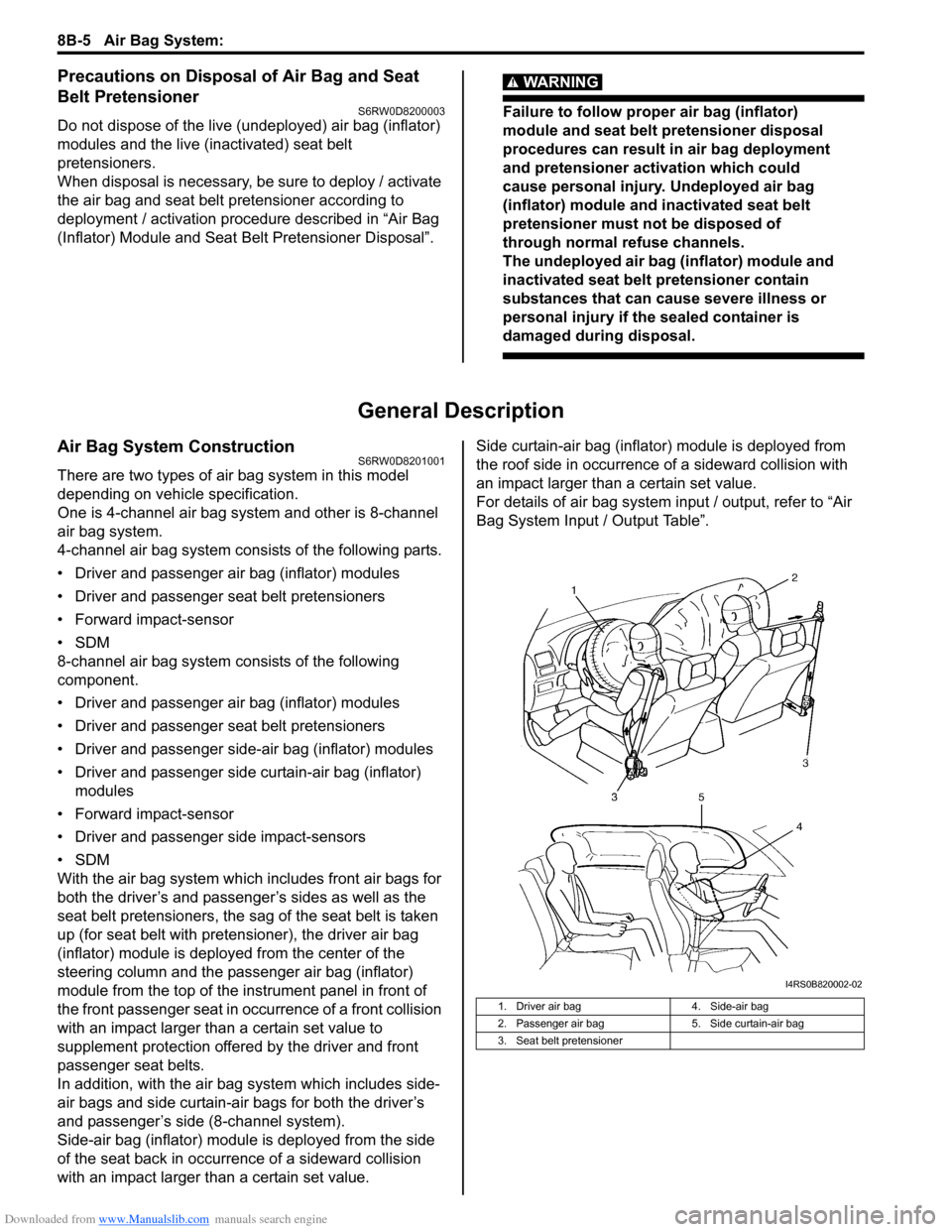
Air Bag System ConstructionS6RW0D8201001
There are two types of air bag system in this model
depending on vehicle specification.
One is 4-channel air bag system and other is 8-channel
air bag system.
4-channel air bag system consists of the following parts.
• Driver and passenger air bag (inflator) modules
• Driver and passenger seat belt pretensioners
• Forward impact-sensor
•SDM
8-channel air bag system consists of the following
component.
• Driver and passenger air bag (inflator) modules
• Driver and passenger seat belt pretensioners
• Driver and passenger side-air bag (inflator) modules
• Driver and passenger side curtain-air bag (inflator)
modules
• Forward impact-sensor
• Driver and passenger side impact-sensors
•SDM
With the air bag system which includes front air bags for
both the driver’s and passenger’s sides as well as the
seat belt pretensioners, the sag of the seat belt is taken
up (for seat belt with pretensioner), the driver air bag
(inflator) module is deployed from the center of the
steering column and the passenger air bag (inflator)
module from the top of the instrument panel in front of
the front passenger seat in occurrence of a front collision
with an impact larger than a certain set value to
supplement protection offered by the driver and front
passenger seat belts.
In addition, with the air bag system which includes side-
air bags and side curtain-air bags for both the driver’s
and passenger’s side (8-channel system).
Side-air bag (inflator) module is deployed from the side
of the seat back in occurrence of a sideward collision
with an impact larger than a certain set value.Side curtain-air bag (inflator) module is deployed from
the roof side in occurrence of a sideward collision with
an impact larger than a certain set value.
For details of air bag system input / output, refer to “Air
Bag System Input / Output Table”.
1. Driver air bag 4. Side-air bag
2. Passenger air bag 5. Side curtain-air bag
3. Seat belt pretensioner
I4RS0B820002-02
Page 1051 of 1556
Downloaded from www.Manualslib.com manuals search engine Air Bag System: 8B-12
Diagnostic Information and Procedures
Air Bag Diagnostic System CheckS6RW0D8204001
WARNING!
To avoid deployment when troubleshooting
the air bag system, do not use electrical test
equipment such as a battery powered or AC
powered voltmeter, ohmmeter, etc., or any
type of electrical equipment other than that
specified in this manual. Do not use a non-
powered probe type tester.
Instructions in this manual must be followed
carefully, otherwise personal injury may
result.
CAUTION!
• The order in which DTCs are diagnosed is
very important. Failure to diagnose the
DTCs in the order specified may result in
extended diagnostic time, incorrect
diagnosis and incorrect parts replacement.
• When measurement of resistance or
voltage is required in the flow, use a tester
along with a correct terminal adapter from
special tool (Connector test adapter kit).
• When a check for proper connection is
required, refer to “Inspection of
Intermittent and Poor Connections”.
• If an open circuit in the air bag wire
harness damaged, connector or terminal is
found, replace the wire harness,
connectors and terminals as an assembly.
The diagnostic procedures used are designed to find
and repair air bag system malfunctions.
To get the best results, it is important to use the
diagnostic flow and follow the sequence in the following.
1) Perform the “Air Bag Diagnostic System Check
Flow”.
(The “Air Bag Diagnostic System Check Flow” must
be the starting point of any air bag system diagnosis.
The “Air Bag Diagnostic System Check Flow” checks
for proper “AIR BAG” warning light operation through
“AIR BAG” warning light and whether air bag DTCs
exist.)
2) Refer to the proper diagnostic flow as directed by the
“Air Bag Diagnostic System Check Flow”.
(The “Air Bag Diagnostic System Check Flow” will
lead you to the correct flow to diagnose any air bag
system malfunctions. Bypassing these procedures
may result in extended diagnostic time, incorrect
diagnosis and incorrect parts replacement.)
3) Repeat the “Air Bag Diagnostic System Check Flow”
after any repair or diagnostic procedures have been
performed.
(Performing the “Air Bag Diagnostic System Check
Flow” after all repair or diagnostic procedures will
ensure that the repair has been made correctly and
that no other malfunctions exist.)
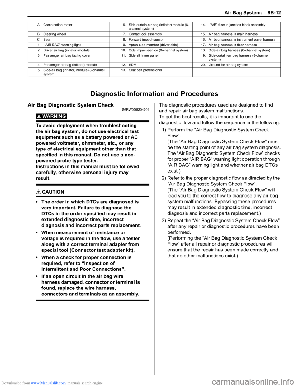
A: Combination meter 6. Side curtain-air bag (inflator) module (8-
channel system)14. “A/B” fuse in junction block assembly
B: Steering wheel 7. Contact coil assembly 15. Air bag harness in main harness
C: Seat 8. Forward impact-sensor 16. Air bag harness in instrument panel harness
1. “AIR BAG” warning light 9. Apron-side-member (driver side) 17. Air bag harness in floor harness
2. Driver air bag (inflator) module 10. Side impact-sensor (8-channel system) 18. Side-air bag harness (8-channel system)
3. Passenger air bag facing cover 11. Side sill inner panel 19. Side curtain-air bag harness (8-channel
system)
4. Passenger air bag (inflator) module 12. SDM 20. Ground for air bag system
5. Side-air bag (inflator) module (8-channel
system)13. Seat belt pretensioner
Page 1503 of 1556
Downloaded from www.Manualslib.com manuals search engine Immobilizer Control System: 10C-1
Control Systems
Immobilizer Control System
Precautions
Precautions in Diagnosing TroublesS6RW0DA300001
• Before confirming the diagnostic trouble code (DTC),
do not disconnect connector from ECM, battery cable
from battery, ground wire harness, or main fuse. Such
disconnection will erase DTC stored in ECM.
• DTC stored in ECM memory can be checked as well
as cleared by using SUZUKI scan tool. Before using
SUZUKI scan tool, read its operator’s manual
carefully to know how to use it and what functions are
available.
• Be sure to read “Precautions for Electrical Circuit
Service in Section 00” before inspection.
• Communication of ECM, BCM, ABS control module,
TCM (if equipped), 4WD control module (if equipped),
keyless start control module (if equipped),
combination meter and DLC is established by CAN
(Controller Area Network). Therefore, handle CAN
communication lines with care referring to “Precaution
for CAN Communication System in Section 00”.
For CAN communication system, refer to description
on “CAN Communication System Description in
Section 1A”.
Precaution in Replacing ECMS6RW0DA300002
• If ECM is replaced with new or used one without
Immobilizer control function, the engine will not be
started. In case of the above, check if the newly
installed ECM has Immobilizer control function.
• After ECM is replaced with new one or used one, the
transponder code in the transponder built in the
ignition key has to be registered with ECM. Or, the
engine cannot be started up. For the registration
procedure, refer to “Procedure after ECM
Replacement”.
Precaution in Replacing Ignition KeyS6RW0DA300003
To register ignition key in case of replacing key(s) and/or
making spare key(s), the transponder code in the ignition
key is registered with ECM. Or the engine can not be
started up. For the registration procedure, refer to
“Registration of the Ignition Key”.
Precautions in Handling Immobilizer Control
System
S6RW0DA300004
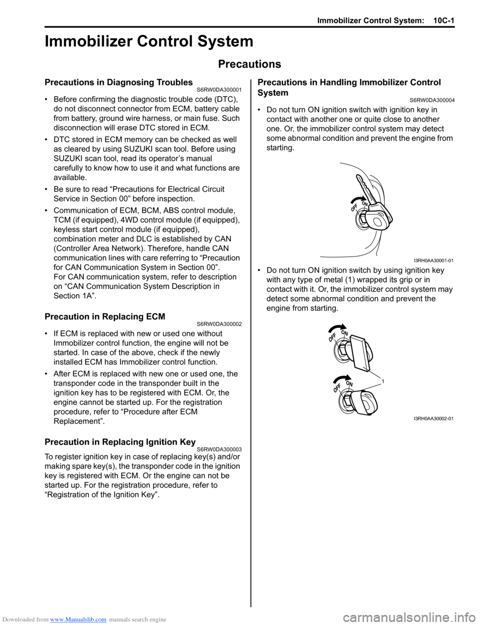
• Do not turn ON ignition switch with ignition key in
contact with another one or quite close to another
one. Or, the immobilizer control system may detect
some abnormal condition and prevent the engine from
starting.
• Do not turn ON ignition switch by using ignition key
with any type of metal (1) wrapped its grip or in
contact with it. Or, the immobilizer control system may
detect some abnormal condition and prevent the
engine from starting.
I3RH0AA30001-01
1
I3RH0AA30002-01
Page 1506 of 1556
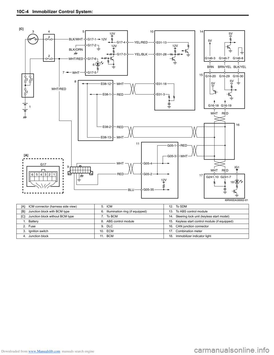
Downloaded from www.Manualslib.com manuals search engine 10C-4 Immobilizer Control System:
BLK/WHT
BLK/ORN12V
G17-1
G17-2
12V
5V
12V
12VYEL/RED
YEL/BLK
G17-4
G17-3
5V
BRNBRN/YELBLK/YEL
1 2
22
2 34
251014
15
1 2 3
4 G17
[A]
5
6
G16-20 G16-29 G16-30 G146-3 G146-7 G146-8
WHT/RED
5V
5V
9
G16-18G16-19 E01-13
E01-28
BLU
RED
WHTE08-12
E08-1E01-18
E01-3
RED
WHTE08-13
E08-2
WHT
RED
G05-4
G05-2
12V
G05-35 8
11
G17-5WHT 76
G17-6WHT/RED
17
REDWHT
REDWHT
G241-10 G241-7
IG1
18
WHT
REDG05-1
G05-3
16 [C]
I6RW0DA30002-01
[A]: ICM connector (harness side view) 5. ICM 12. To SDM
[B]: Junction block with BCM type 6. Illumination ring (if equipped) 13. To ABS control module
[C]: Junction block without BCM type 7. To BCM 14. Steering lock unit (keyless start model)
1. Battery 8. ABS control module 15. Keyless start control module (if equipped)
2. Fuse 9. DLC 16. CAN junction connector
3. Ignition switch 10. ECM 17. Combination meter
4. Junction block 11. BCM 18. Immobilizer indicator light