Fuel System SUZUKI SX4 2006 1.G Service Workshop Manual
[x] Cancel search | Manufacturer: SUZUKI, Model Year: 2006, Model line: SX4, Model: SUZUKI SX4 2006 1.GPages: 1556, PDF Size: 37.31 MB
Page 1235 of 1556
Downloaded from www.Manualslib.com manuals search engine Wiring Systems: 9A-68
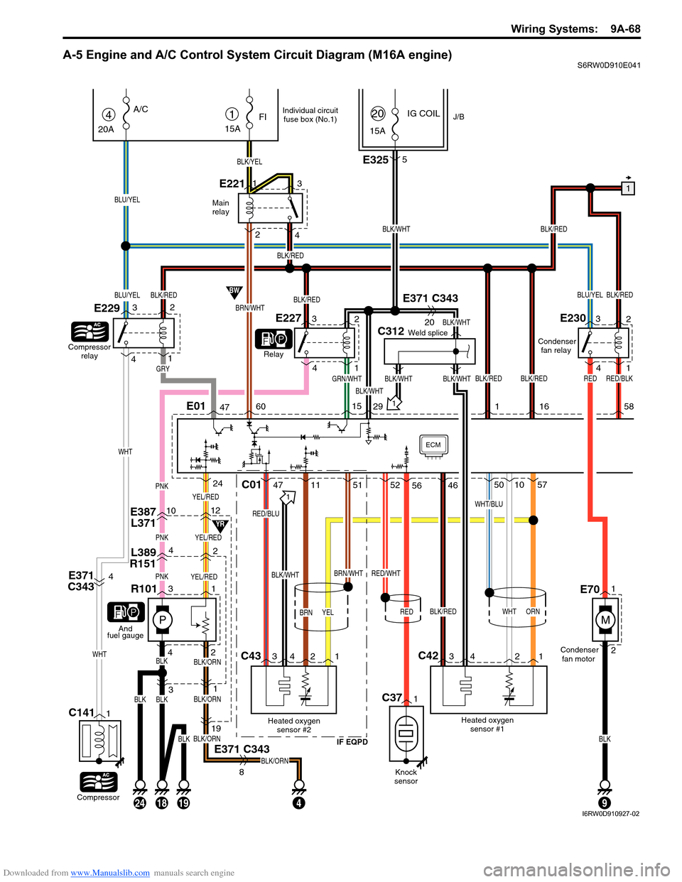
A-5 Engine and A/C Control System Circuit Diagram (M16A engine)S6RW0D910E041
YEL/RED
E387
L3711012
L389
R15142
PNKYEL/RED
P
PNKYEL/RED
31
4
31
E371 C343
BLK/ORN
BLK/ORN
BLK/ORN
BLK/ORN
19
8
BLK42
R101
1
And
fuel gauge
Main
relay
1
BLK/WHT
BLK/REDBLU/YEL
C312Weld splice
GRN/WHTBLK/WHT
BLK/WHT
BLK/WHT
IG COILJ/B1
15A
FI
BLK/YEL
E2211
23
415A
20
BRN/WHT
BW
YR
4
20A
A/C
Compressor
relay
E229
Relay
BLU/YEL
BLU/YEL
Compressor
C1411
E3255
E371 C343
20
E371
C3434BLK/WHT
C43C42
Heated oxygen
sensor #2
IF EQPD
RED/BLU
BRN
Heated oxygen
sensor #1Condenser
fan motor Condenser
fan relay
WHT
BRN/WHT
BLK/RED
WHT/BLU
C01
1
34 2 134 2 1
471151
RED/WHT
52461050
ORN
57PNK
ECM
142
3
WHT
WHT
BLK/RED
BLK/REDBLK/WHT
BLK/RED
BLK/RED
BLK/RED
E01476015291
GRY
E22732
4
1
E23032
4
1
YEL
24
BLKBLK
56
BLK/REDRED
16 58
182419
Individual circuit
fuse box (No.1)
BLKBLK
9
RED/BLK
M
1
2E70
RED
Knock
sensor
C371
I6RW0D910927-02
Page 1239 of 1556
Downloaded from www.Manualslib.com manuals search engine Wiring Systems: 9A-72
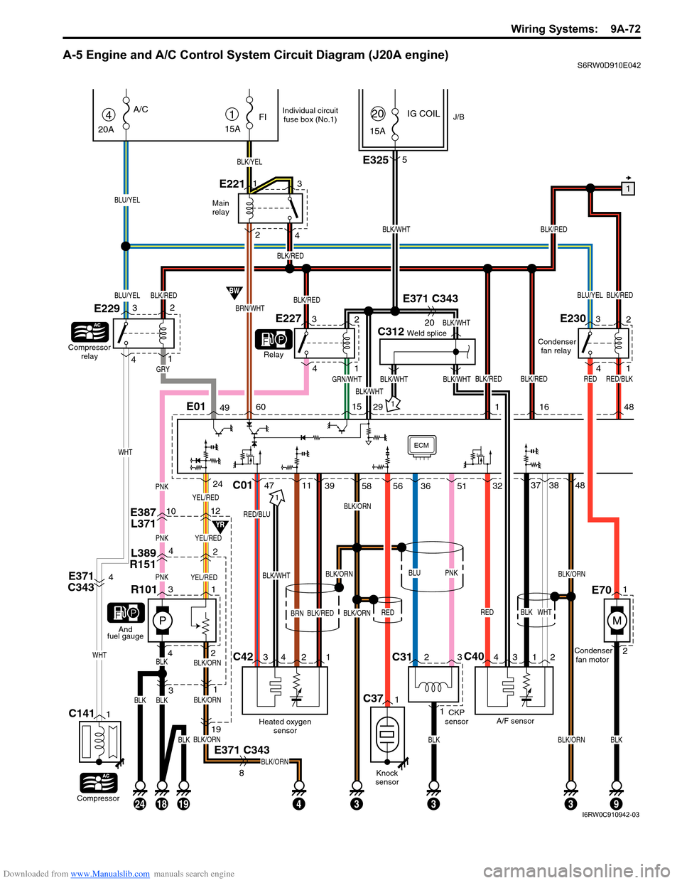
A-5 Engine and A/C Control System Circuit Diagram (J20A engine)S6RW0D910E042
YEL/RED
E387
L3711012
L389
R15142
PNKYEL/RED
P
PNKYEL/RED
31
433
31
E371 C343
BLK/ORN
BLK/ORN
BLK/ORN
BLK/ORN
19
8
BLK42
R101
1
And
fuel gauge
Main
relay
1
BLK/WHT
BLK/REDBLU/YEL
C312Weld splice
GRN/WHTBLK/WHT
BLK/WHT
BLK/WHT
IG COILJ/B1
15A
FI
BLK/YEL
E2211
23
415A
20
BRN/WHT
BW
YR
4
20A
A/C
Compressor
relay
E229
Relay
BLU/YEL
BLU/YEL
Compressor
C1411
C312
13
E3255
E371 C343
20
E371
C3434BLK/WHT
C42C40
Heated oxygen
sensor
RED/BLU
BRN
A/F sensor CKP
sensorCondenser
fan motor Condenser
fan relay
BLK
BLK/ORNBLK/ORN
BLK/ORN
RED
C01
1
34 2 143 12
4711393237
WHT
3848PNK
ECM
142
3
WHT
WHT
BLK/RED
BLK/REDBLK/WHT
BLK/RED
BLK/RED
BLK/RED
E01496015291
GRY
E22732
4
1
E23032
4
1
BLK/REDBLK/ORN
24
BLKBLK
58 56
BLK/REDRED
16 48
182419
Individual circuit
fuse box (No.1)
BLKBLKBLK/ORNBLK
93
RED/BLK
M
1
2E70
3651
BLUPNK
RED
Knock
sensor
C371
I6RW0C910942-03
Page 1271 of 1556

Downloaded from www.Manualslib.com manuals search engine Wiring Systems: 9A-104
C-1 Combination Meter Circuit Diagram (Meter)S6RW0D910E019
DOMEJ/B
15A
37MTR
10A22
WHT/RED
WHT/RED
(CAN)
G24132 315
Stepper motor and LED
output driver
Voltage regulator
Micro controller
Interface circuit
ILL
(Dial)ILL
(Display)ILL
(Pointer)
G2716
RED/BLK
16
B
B
BLK
BLK
BLK
BLK
J/C
G309
FUEL TEMP TACHO SPEED
1114
CAN
Low High
WHTRED
WHTRED
LCD
"A-8"RW
10
7
BCM
B
B
J/C
G308
A
A
J/C
B
BG311
I6RW0C910973-01
Page 1274 of 1556
Downloaded from www.Manualslib.com manuals search engine 9A-107 Wiring Systems:
GEAR
ABS
BELT
DOOR
CHARGE
CHECK ENGINEAIRBAG
OILDRLD/F LOCK4WD AUTO
SETCRUISEIMMOBI
BRAKE
FUEL
DOME
15A37
32 5
WHT/RED
WHT/RED
J/B
G271
G241
1
2
J/C
G308B
B
IF EQPD
I6RW0C910976-01
Page 1353 of 1556

Downloaded from www.Manualslib.com manuals search engine Instrumentation / Driver Info. / Horn: 9C-1
Body, Cab and Accessories
Instrumentation / Driver Info. / Horn
Precautions
Precautions in Diagnosing Troubles for Combination MeterS6RW0D9300001
Combination meter uses signals (information) from each control module by CAN communication to control
speedometer, tachometer, fuel meter, engine coolant temp meter, warning light and indicator light (other than air bag
warning light, EPS warning light, headlight leveling warning light (if equipped), rear fog light indicator light (if
equipped), high beam indicator light and turn signal indicator light). Therefor, check that no DTC is detected in each
module before performing combination meter symptom diagnosis. If any DTC is detected, correct trouble indicated by
that DTC troubleshooting first.
General Description
CAN Communication System DescriptionS6RW0D9301001
Refer to “CAN Communication System Description in Section 1A” for CAN communication system description.
Combination meter communicates control data with each control module as follows.
Combination Meter Transmission Data
BCM
Combination
meterDATA
TransmitCombination meter spec signal
I5RW0A930001-02
Page 1354 of 1556
Downloaded from www.Manualslib.com manuals search engine 9C-2 Instrumentation / Driver Info. / Horn:
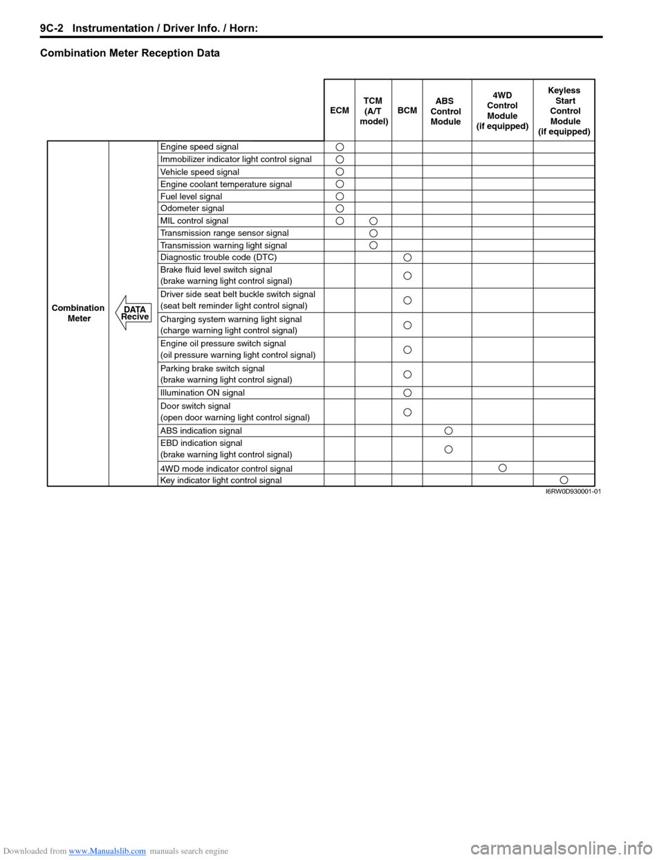
Combination Meter Reception Data
ECM BCM
Keyless
Start
Control
Module
(if equipped)
Combination
Meter4WD
Control
Module
(if equipped)TCM
(A/T
model)
Engine speed signal
Immobilizer indicator light control signal
Vehicle speed signal
Engine coolant temperature signal
Fuel level signal
MIL control signal
Transmission range sensor signal
Transmission warning light signal
Diagnostic trouble code (DTC)
Brake fluid level switch signal
(brake warning light control signal)
Driver side seat belt buckle switch signal
(seat belt reminder light control signal)
Charging system warning light signal
(charge warning light control signal)
Engine oil pressure switch signal
(oil pressure warning light control signal)
Parking brake switch signal
(brake warning light control signal)
Illumination ON signal
Door switch signal
(open door warning light control signal)
ABS indication signal
EBD indication signal
(brake warning light control signal)
4WD mode indicator control signal
Key indicator light control signal
ABS
Control
Module
Odometer signal
DATA
Recive
I6RW0D930001-01
Page 1363 of 1556
Downloaded from www.Manualslib.com manuals search engine Instrumentation / Driver Info. / Horn: 9C-11
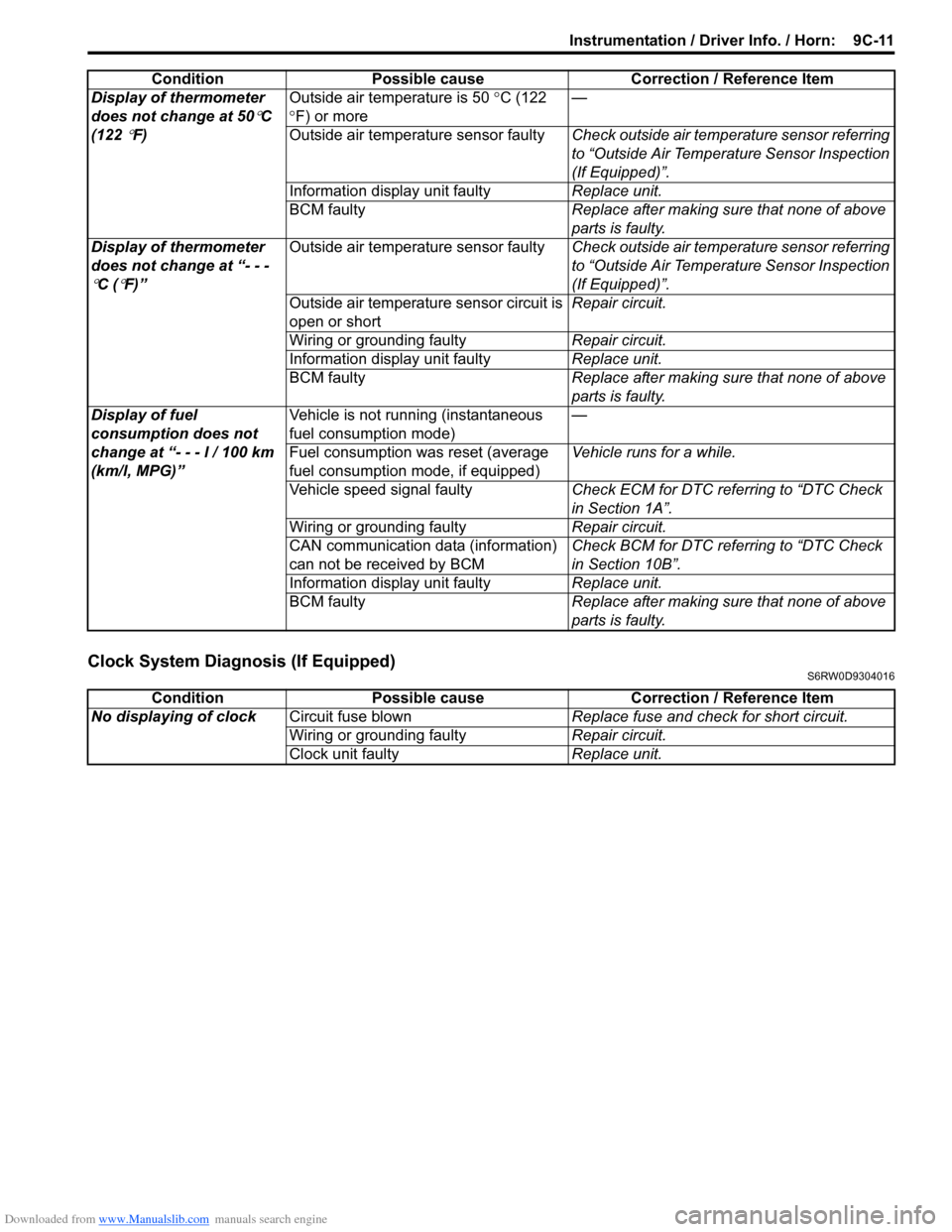
Clock System Diagnosis (If Equipped)S6RW0D9304016
Display of thermometer
does not change at 50
°C
(122
°F)Outside air temperature is 50 °C (122
°F) or more—
Outside air temperature sensor faultyCheck outside air temperature sensor referring
to “Outside Air Temperature Sensor Inspection
(If Equipped)”.
Information display unit faultyReplace unit.
BCM faultyReplace after making sure that none of above
parts is faulty.
Display of thermometer
does not change at “- - -
°C (°F)”Outside air temperature sensor faultyCheck outside air temperature sensor referring
to “Outside Air Temperature Sensor Inspection
(If Equipped)”.
Outside air temperature sensor circuit is
open or shortRepair circuit.
Wiring or grounding faultyRepair circuit.
Information display unit faultyReplace unit.
BCM faultyReplace after making sure that none of above
parts is faulty.
Display of fuel
consumption does not
change at “- - - l / 100 km
(km/l, MPG)”Vehicle is not running (instantaneous
fuel consumption mode)—
Fuel consumption was reset (average
fuel consumption mode, if equipped)Vehicle runs for a while.
Vehicle speed signal faultyCheck ECM for DTC referring to “DTC Check
in Section 1A”.
Wiring or grounding faultyRepair circuit.
CAN communication data (information)
can not be received by BCMCheck BCM for DTC referring to “DTC Check
in Section 10B”.
Information display unit faultyReplace unit.
BCM faultyReplace after making sure that none of above
parts is faulty. Condition Possible cause Correction / Reference Item
Condition Possible cause Correction / Reference Item
No displaying of clockCircuit fuse blownReplace fuse and check for short circuit.
Wiring or grounding faultyRepair circuit.
Clock unit faultyReplace unit.
Page 1475 of 1556
Downloaded from www.Manualslib.com manuals search engine Body Electrical Control System: 10B-2
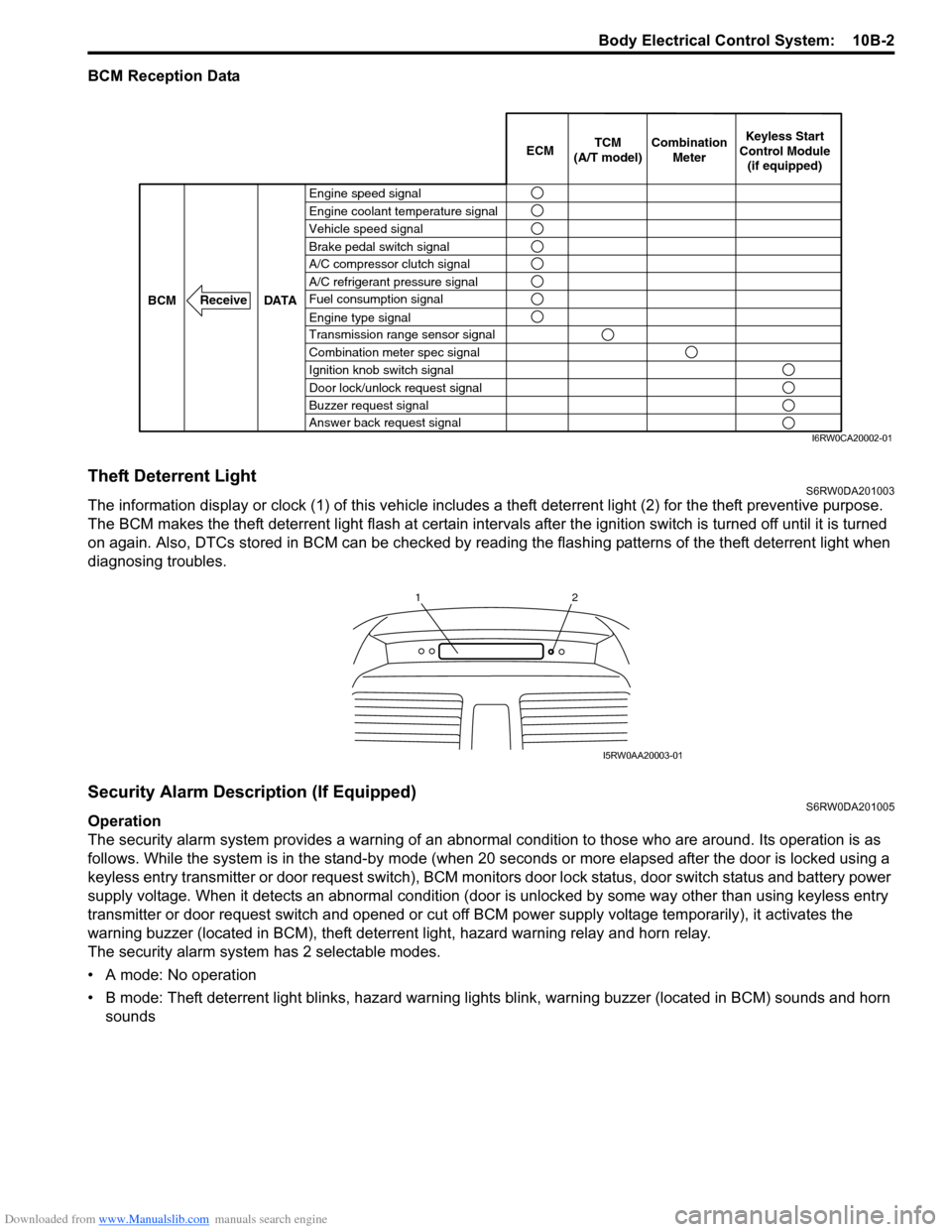
BCM Reception Data
Theft Deterrent LightS6RW0DA201003
The information display or clock (1) of this vehicle includes a theft deterrent light (2) for the theft preventive purpose.
The BCM makes the theft deterrent light flash at certain intervals after the ignition switch is turned off until it is turned
on again. Also, DTCs stored in BCM can be checked by reading the flashing patterns of the theft deterrent light when
diagnosing troubles.
Security Alarm Description (If Equipped)S6RW0DA201005
Operation
The security alarm system provides a warning of an abnormal condition to those who are around. Its operation is as
follows. While the system is in the stand-by mode (when 20 seconds or more elapsed after the door is locked using a
keyless entry transmitter or door request switch), BCM monitors door lock status, door switch status and battery power
supply voltage. When it detects an abnormal condition (door is unlocked by some way other than using keyless entry
transmitter or door request switch and opened or cut off BCM power supply voltage temporarily), it activates the
warning buzzer (located in BCM), theft deterrent light, hazard warning relay and horn relay.
The security alarm system has 2 selectable modes.
• A mode: No operation
• B mode: Theft deterrent light blinks, hazard warning lights blink, warning buzzer (located in BCM) sounds and horn
sounds
Engine speed signal
Vehicle speed signal Engine coolant temperature signal
Brake pedal switch signal
A/C refrigerant pressure signal
Fuel consumption signal A/C compressor clutch signal
Engine type signal
Transmission range sensor signal
Combination meter spec signal
Ignition knob switch signal
Door lock/unlock request signal
Buzzer request signal
Answer back request signal DATA BCM
Receive
Combination
Meter TCM
(A/T model)Keyless Start
Control Module
(if equipped) ECM
I6RW0CA20002-01
12
I5RW0AA20003-01
Page 1484 of 1556
Downloaded from www.Manualslib.com manuals search engine 10B-11 Body Electrical Control System:
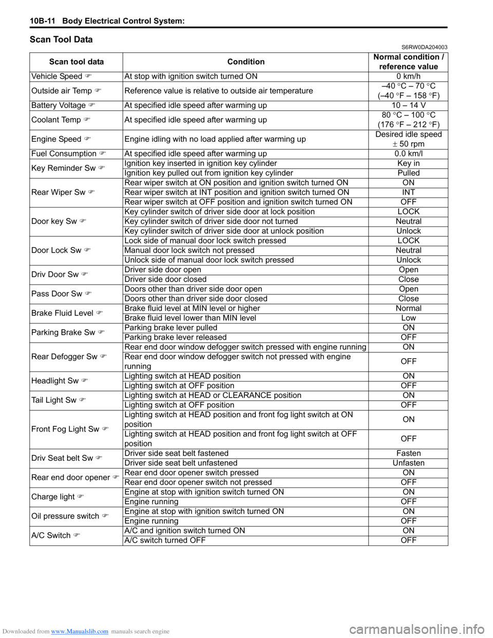
Scan Tool DataS6RW0DA204003
Scan tool data ConditionNormal condition /
reference value
Vehicle Speed �)At stop with ignition switch turned ON 0 km/h
Outside air Temp �)Reference value is relative to outside air temperature–40 °C – 70 °C
(–40 °F – 158 °F)
Battery Voltage �)At specified idle speed after warming up 10 – 14 V
Coolant Temp �)At specified idle speed after warming up80 °C – 100 °C
(176 °F – 212 °F)
Engine Speed �)Engine idling with no load applied after warming upDesired idle speed
± 50 rpm
Fuel Consumption �)At specified idle speed after warming up 0.0 km/l
Key Reminder Sw �)Ignition key inserted in ignition key cylinder Key in
Ignition key pulled out from ignition key cylinder Pulled
Rear Wiper Sw �)Rear wiper switch at ON position and ignition switch turned ON ON
Rear wiper switch at INT position and ignition switch turned ON INT
Rear wiper switch at OFF position and ignition switch turned ON OFF
Door key Sw �)Key cylinder switch of driver side door at lock position LOCK
Key cylinder switch of driver side door not turned Neutral
Key cylinder switch of driver side door at unlock position Unlock
Door Lock Sw �)Lock side of manual door lock switch pressed LOCK
Manual door lock switch not pressed Neutral
Unlock side of manual door lock switch pressed Unlock
Driv Door Sw �)Driver side door open Open
Driver side door closed Close
Pass Door Sw �)Doors other than driver side door open Open
Doors other than driver side door closed Close
Brake Fluid Level �)Brake fluid level at MIN level or higher Normal
Brake fluid level lower than MIN level Low
Parking Brake Sw �)Parking brake lever pulled ON
Parking brake lever released OFF
Rear Defogger Sw �)Rear end door window defogger switch pressed with engine running ON
Rear end door window defogger switch not pressed with engine
runningOFF
Headlight Sw �)Lighting switch at HEAD position ON
Lighting switch at OFF position OFF
Tail Light Sw �)Lighting switch at HEAD or CLEARANCE position ON
Lighting switch at OFF position OFF
Front Fog Light Sw �)Lighting switch at HEAD position and front fog light switch at ON
positionON
Lighting switch at HEAD position and front fog light switch at OFF
positionOFF
Driv Seat belt Sw
�)Driver side seat belt fastened Fasten
Driver side seat belt unfastened Unfasten
Rear end door opener �)Rear end door opener switch pressed ON
Rear end door opener switch not pressed OFF
Charge light �)Engine at stop with ignition switch turned ON ON
Engine running OFF
Oil pressure switch �)Engine at stop with ignition switch turned ON ON
Engine running OFF
A/C Switch �)A/C and ignition switch turned ON ON
A/C switch turned OFF OFF
Page 1485 of 1556
Downloaded from www.Manualslib.com manuals search engine Body Electrical Control System: 10B-12
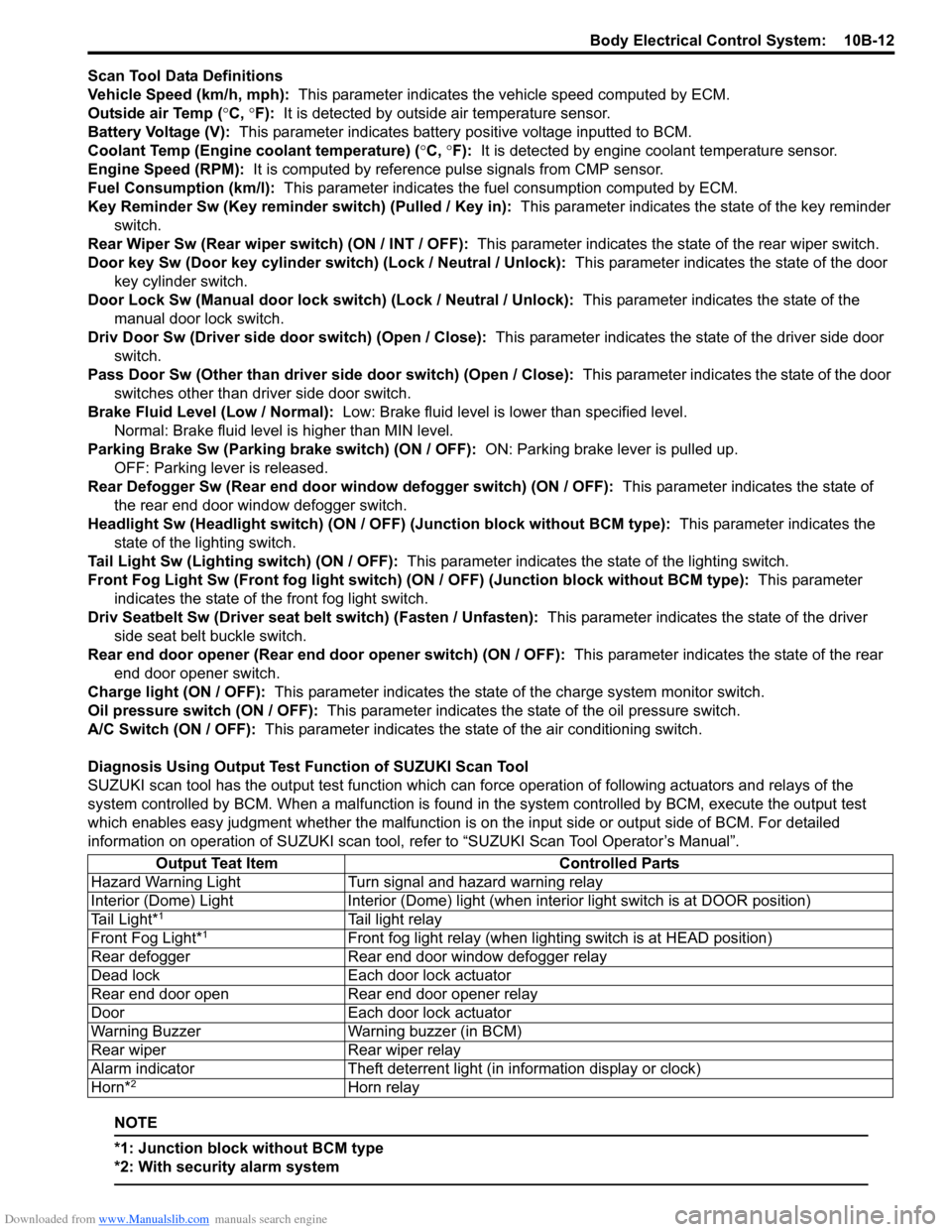
Scan Tool Data Definitions
Vehicle Speed (km/h, mph): This parameter indicates the vehicle speed computed by ECM.
Outside air Temp (°C, °F): It is detected by outside air temperature sensor.
Battery Voltage (V): This parameter indicates battery positive voltage inputted to BCM.
Coolant Temp (Engine coolant temperature) (°C, °F): It is detected by engine coolant temperature sensor.
Engine Speed (RPM): It is computed by reference pulse signals from CMP sensor.
Fuel Consumption (km/l): This parameter indicates the fuel consumption computed by ECM.
Key Reminder Sw (Key reminder switch) (Pulled / Key in): This parameter indicates the state of the key reminder
switch.
Rear Wiper Sw (Rear wiper switch) (ON / INT / OFF): This parameter indicates the state of the rear wiper switch.
Door key Sw (Door key cylinder switch) (Lock / Neutral / Unlock): This parameter indicates the state of the door
key cylinder switch.
Door Lock Sw (Manual door lock switch) (Lock / Neutral / Unlock): This parameter indicates the state of the
manual door lock switch.
Driv Door Sw (Driver side door switch) (Open / Close): This parameter indicates the state of the driver side door
switch.
Pass Door Sw (Other than driver side door switch) (Open / Close): This parameter indicates the state of the door
switches other than driver side door switch.
Brake Fluid Level (Low / Normal): Low: Brake fluid level is lower than specified level.
Normal: Brake fluid level is higher than MIN level.
Parking Brake Sw (Parking brake switch) (ON / OFF): ON: Parking brake lever is pulled up.
OFF: Parking lever is released.
Rear Defogger Sw (Rear end door window defogger switch) (ON / OFF): This parameter indicates the state of
the rear end door window defogger switch.
Headlight Sw (Headlight switch) (ON / OFF) (Junction block without BCM type): This parameter indicates the
state of the lighting switch.
Tail Light Sw (Lighting switch) (ON / OFF): This parameter indicates the state of the lighting switch.
Front Fog Light Sw (Front fog light switch) (ON / OFF) (Junction block without BCM type): This parameter
indicates the state of the front fog light switch.
Driv Seatbelt Sw (Driver seat belt switch) (Fasten / Unfasten): This parameter indicates the state of the driver
side seat belt buckle switch.
Rear end door opener (Rear end door opener switch) (ON / OFF): This parameter indicates the state of the rear
end door opener switch.
Charge light (ON / OFF): This parameter indicates the state of the charge system monitor switch.
Oil pressure switch (ON / OFF): This parameter indicates the state of the oil pressure switch.
A/C Switch (ON / OFF): This parameter indicates the state of the air conditioning switch.
Diagnosis Using Output Test Function of SUZUKI Scan Tool
SUZUKI scan tool has the output test function which can force operation of following actuators and relays of the
system controlled by BCM. When a malfunction is found in the system controlled by BCM, execute the output test
which enables easy judgment whether the malfunction is on the input side or output side of BCM. For detailed
information on operation of SUZUKI scan tool, refer to “SUZUKI Scan Tool Operator’s Manual”.
NOTE
*1: Junction block without BCM type
*2: With security alarm system
Output Teat Item Controlled Parts
Hazard Warning Light Turn signal and hazard warning relay
Interior (Dome) Light Interior (Dome) light (when interior light switch is at DOOR position)
Tail Light*
1Tail light relay
Front Fog Light*1Front fog light relay (when lighting switch is at HEAD position)
Rear defogger Rear end door window defogger relay
Dead lock Each door lock actuator
Rear end door open Rear end door opener relay
Door Each door lock actuator
Warning Buzzer Warning buzzer (in BCM)
Rear wiper Rear wiper relay
Alarm indicator Theft deterrent light (in information display or clock)
Horn*
2Horn relay