SUZUKI SX4 2006 1.G Service Workshop Manual
Manufacturer: SUZUKI, Model Year: 2006, Model line: SX4, Model: SUZUKI SX4 2006 1.GPages: 1556, PDF Size: 37.31 MB
Page 1171 of 1556
![SUZUKI SX4 2006 1.G Service Workshop Manual Downloaded from www.Manualslib.com manuals search engine Wiring Systems: 9A-4
How to Read Connector Layout DiagramS6RW0D9101004
[A-1]: Harness symbol and corresponding harness name
A: Battery harness SUZUKI SX4 2006 1.G Service Workshop Manual Downloaded from www.Manualslib.com manuals search engine Wiring Systems: 9A-4
How to Read Connector Layout DiagramS6RW0D9101004
[A-1]: Harness symbol and corresponding harness name
A: Battery harness](/img/20/7612/w960_7612-1170.png)
Downloaded from www.Manualslib.com manuals search engine Wiring Systems: 9A-4
How to Read Connector Layout DiagramS6RW0D9101004
[A-1]: Harness symbol and corresponding harness name
A: Battery harness
B: A/C harness
C: Engine harness
D: Injector harness
E: Main harness, Oil pressure switch wire, Console wire
G: Instrument panel harness
J: Side door wire (Power window)
K: Interior light harness, Rear speaker wire, Roof wire
L: Floor harness, G sensor wire (Fuel pump harness)
M: Rear bumper harness
O: Rear end door harness
Q: Air bag/Pretensioner harness
R: (Fuel pump wire)
[A-2]: Connector Number
[B]: Ground point No.
12
11
[B][B]
Connector code
[A-1] [A-2]L 36
L13L15
R01 L14L12L11L10 L09 L36
R02 L24 L25 L33
L28 L20 L26 (TO O01)
{
L05
L16
L32 L19 L01 (TO G01)
L02 (TO E04)
L03 (TO E05) L42
R05 R04
L07 (TO K02)
I2RH01910901-01
Page 1172 of 1556
Downloaded from www.Manualslib.com manuals search engine 9A-5 Wiring Systems:
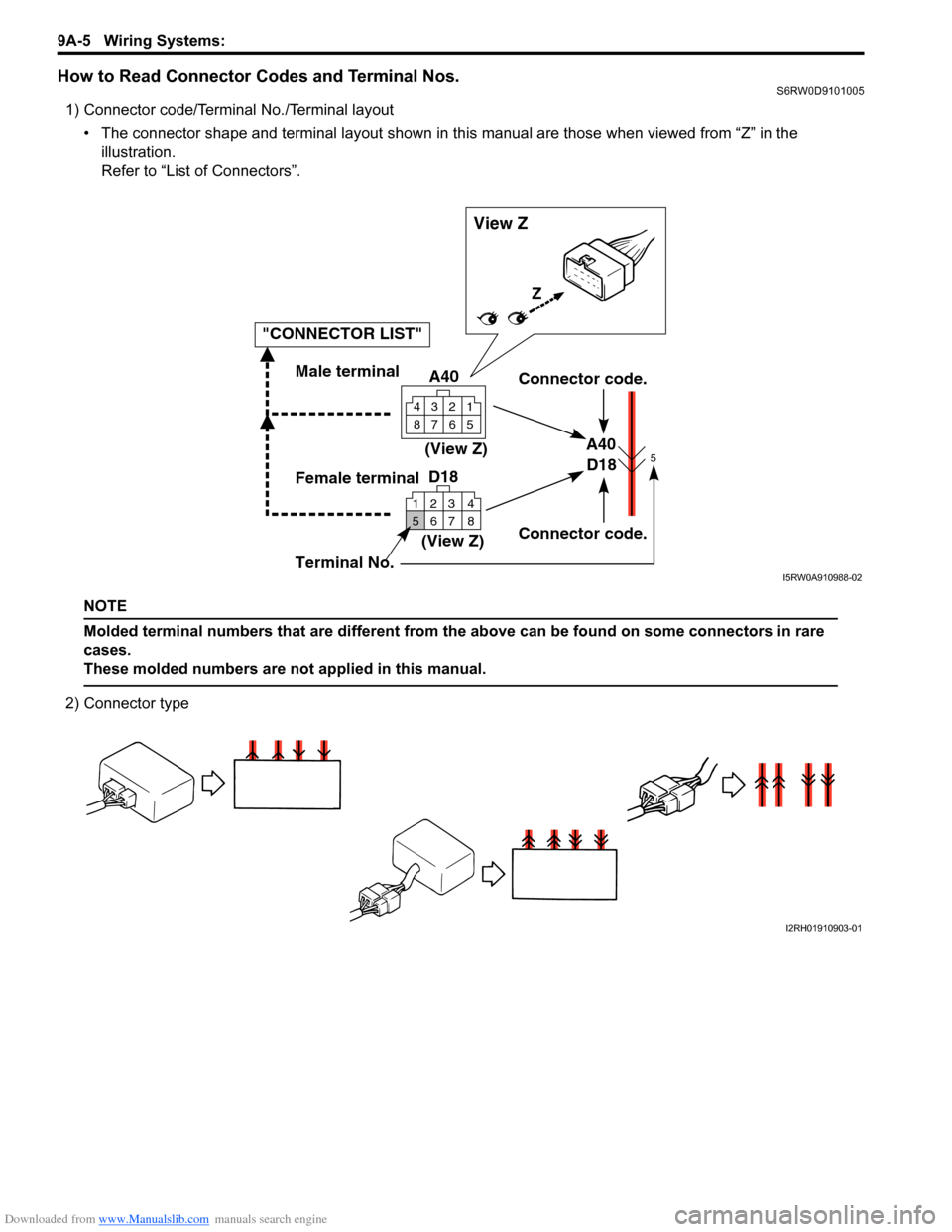
How to Read Connector Codes and Terminal Nos.S6RW0D9101005
1) Connector code/Terminal No./Terminal layout
• The connector shape and terminal layout shown in this manual are those when viewed from “Z” in the
illustration.
Refer to “List of Connectors”.
NOTE
Molded terminal numbers that are different from the above can be found on some connectors in rare
cases.
These molded numbers are not applied in this manual.
2) Connector type
A40
(View Z)
(View Z)
1
123 4
567 82 3 4
5 6 7 8
D185
D18A40
Connector code.
Connector code.
Terminal No.
"CONNECTOR LIST"
Male terminal
Female terminalZ
View Z
I5RW0A910988-02
I2RH01910903-01
Page 1173 of 1556
Downloaded from www.Manualslib.com manuals search engine Wiring Systems: 9A-6
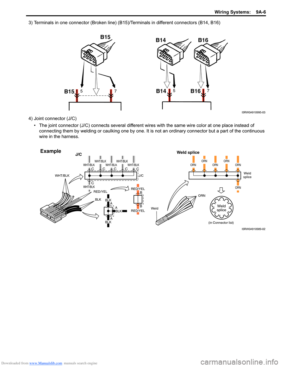
3) Terminals in one connector (Broken line) (B15)/Terminals in different connectors (B14, B16)
4) Joint connector (J/C)
• The joint connector (J/C) connects several different wires with the same wire color at one place instead of
connecting them by welding or caulking one by one. It is not an ordinary connector but a part of the continuous
wire in the harness.
B15B15
B14 B1657B14 B1657
I5RW0A910995-03
BLK
BLK
A
A
AB
B RED/YEL
WeldORN WHT/BLK
J/CWeld splice
BLKBLK
RED/YEL
RED/YEL
WHT/BLK
WHT/BLK
WHT/BLKWHT/BLKWHT/BLKWHT/BLKC
CCCCCWeld
splice
(in Connector list) J/C
ORNORNORNORNORN
ORN
Weld
splice
Example
I5RW0A910989-02
Page 1174 of 1556
Downloaded from www.Manualslib.com manuals search engine 9A-7 Wiring Systems:
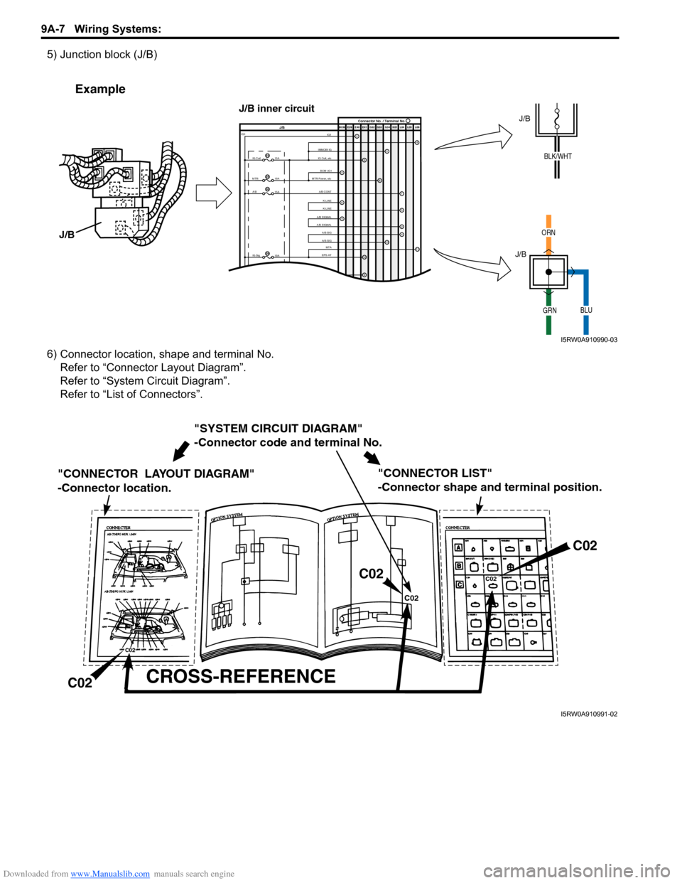
5) Junction block (J/B)
6) Connector location, shape and terminal No.
Refer to “Connector Layout Diagram”.
Refer to “System Circuit Diagram”.
Refer to “List of Connectors”.
IMMOBI IGIG1IG Coil, etcE39 E41E40 BCM G34G33 G32 K01 L04 L05 L06
IG Coil IG1
15A
MTR
10A
A/B
15A
2
65
13
J/BConnector No. / Terminal No.
BCM ;IG1
MTR Power, etc
A/B CONTK-LINE
K-LINE
A/B SIGNAL
A/B SIGNAL
A/B SIG
A/B SIG
IG Sig
10AEPS ATMTA
4
6
1
3
24
8
11
9
12
9
11
23
25
30
29
Example
J/B
J/B
ORN
GRNBLU
J/B
J/B inner circuit
BLK/WHT
I5RW0A910990-03
"SYSTEM CIRCUIT DIAGRAM"
-Connector code and terminal No.
"CONNECTOR LAYOUT DIAGRAM"
-Connector location.
CROSS-REFERENCE
"CONNECTOR LIST"
-Connector shape and terminal position.
C02
C02C02
C02
C02
C02
I5RW0A910991-02
Page 1175 of 1556
Downloaded from www.Manualslib.com manuals search engine Wiring Systems: 9A-8
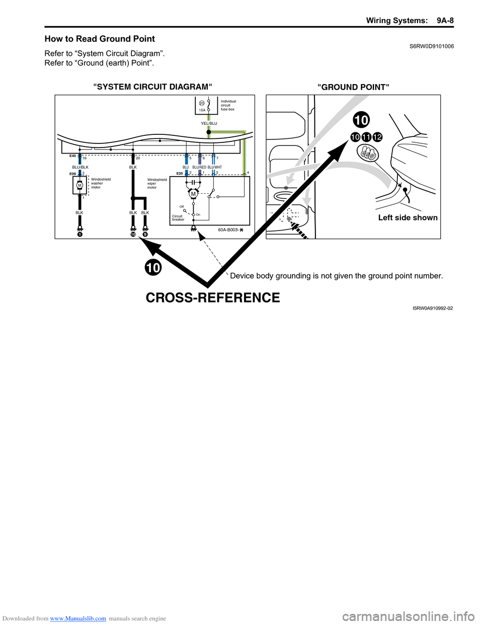
How to Read Ground PointS6RW0D9101006
Refer to “System Circuit Diagram”.
Refer to “Ground (earth) Point”.
Left side shown
101112
"SYSTEM CIRCUIT DIAGRAM"
"GROUND POINT"
CROSS-REFERENCE
Windoshield
washer
motorIndividual
circuit
fuse box
2015A
Windoshield
wiper
motor E40
E09E20 16
2
1
Off
On
Circuit
breaker
60A-B003-
YEL/BLU
1
205
2
134
67
BLU/BLK
BLK
10
BLK
BLK
9
10
10
BLK
M
BLUBLU/WHTBLU/RED
M
Device body grounding is not given the ground point number.
I5RW0A910992-02
Page 1176 of 1556
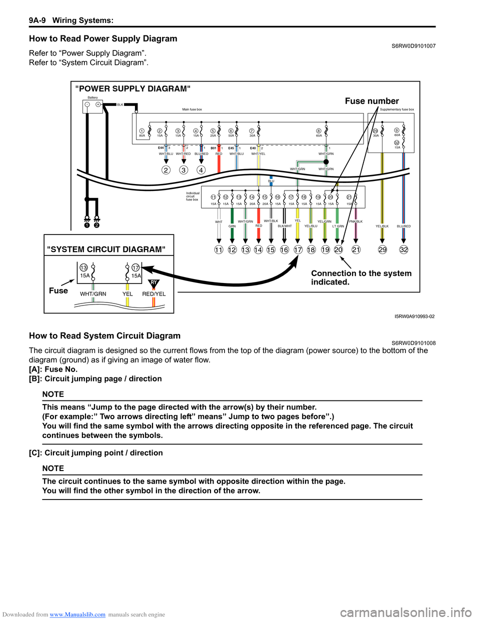
Downloaded from www.Manualslib.com manuals search engine 9A-9 Wiring Systems:
How to Read Power Supply DiagramS6RW0D9101007
Refer to “Power Supply Diagram”.
Refer to “System Circuit Diagram”.
How to Read System Circuit DiagramS6RW0D9101008
The circuit diagram is designed so the current flows from the top of the diagram (power source) to the bottom of the
diagram (ground) as if giving an image of water flow.
[A]: Fuse No.
[B]: Circuit jumping page / direction
NOTE
This means “Jump to the page directed with the arrow(s) by their number.
(For example:” Two arrows directing left” means” Jump to two pages before”.)
You will find the same symbol with the arrows directing opposite in the referenced page. The circuit
continues between the symbols.
[C]: Circuit jumping point / direction
NOTE
The circuit continues to the same symbol with opposite direction within the page.
You will find the other symbol in the direction of the arrow.
Connection to the system
indicated. "POWER SUPPLY DIAGRAM"
-+
1
Battery
80A
215A315A415A525A67850A 30A2930A3215A
960A
60A
BLK
YEL/BLKPNK/BLKLT GRNYEL/GRNYEL/BLUBLK/WHTWHT/BLKWHT/GRNREDGRNWHT
WHT/BLUWHT/REDWHT/BLUWHT/YELWHT/GRN
WHT/GRNWHT/GRN
BLU
BLU/REDRED
YELBLU/RED Individual
circuit
fuse box Main fuse boxSupplementary fuse box
11
11
243
121314151617181920212932
1213141516171819202115A 15A 15A 20A 20A 15A 15A 15A 15A 15A 15A E44321
B011E451E4021
FuseRED/YEL YEL WHT/GRN
15A
15A 1317
"SYSTEM CIRCUIT DIAGRAM"
Fuse number
12
RY
I5RW0A910993-02
Page 1177 of 1556
![SUZUKI SX4 2006 1.G Service Workshop Manual Downloaded from www.Manualslib.com manuals search engine Wiring Systems: 9A-10
[D]: Terminals-in-one-connector mark
[E]: Wire color
[F]: Shield wire
[G]: Ground point
[H]: “From” or “To” (Wit SUZUKI SX4 2006 1.G Service Workshop Manual Downloaded from www.Manualslib.com manuals search engine Wiring Systems: 9A-10
[D]: Terminals-in-one-connector mark
[E]: Wire color
[F]: Shield wire
[G]: Ground point
[H]: “From” or “To” (Wit](/img/20/7612/w960_7612-1176.png)
Downloaded from www.Manualslib.com manuals search engine Wiring Systems: 9A-10
[D]: Terminals-in-one-connector mark
[E]: Wire color
[F]: Shield wire
[G]: Ground point
[H]: “From” or “To” (With ID letter (s))
[I]: Specification variation
The white arrow between A and B means “or”.
[J]: “From” (With ID letter (s))
[K] “To” (With ID letter (s))
[L]: Connector code
[M]: Terminal No.
[N]: Symbol mark
[O]: “SEE” mark
Switch
BLU
BLU
GRN/BLK
GRN/REDGRN/BLK
12
GRN
GRN
C262
1
BLK
5
BLK
2 1
C40
GRN/BLK
"XX"
Solenoid FuseFuse
3
15A
Main
relay
ON OFF
1
15A
6
20A
1
Sensor 1
2
8
BRN/RED
E521
2E521
BRN/RED
RED
2
BRN/REDBRN/RED
MotorM M
655
A
B
AB5
6
1
2
56464 4-DOOR
2-DOOR
2
C71
E03
E34
O06
C31
E19
[A]
[B]
[C]
[F]
[G]
[H] [D][I] [K] [L]
E3375E341
21
43E08
ORNWHTYEL
RED
YELYEL/REDGRN/RED
4
3
YEL
BLK/RED
ORN
GRN
GRN
BA
GRN
GRN
2
XX
Cont.M
[J]
[E]
[N] [O] [M]
GBGR
Y
Y
GB
P
3
4
2
3
L50 G20
1
GR
Y
BLK
BLK
GR
I5RW0A910994-02
Page 1178 of 1556
Downloaded from www.Manualslib.com manuals search engine 9A-11 Wiring Systems:
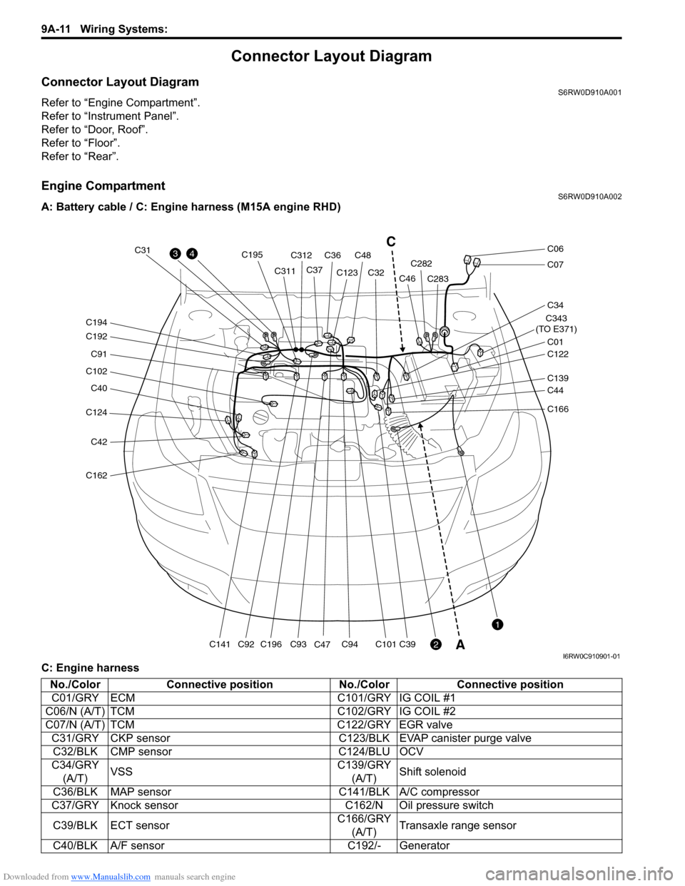
Connector Layout Diagram
Connector Layout DiagramS6RW0D910A001
Refer to “Engine Compartment”.
Refer to “Instrument Panel”.
Refer to “Door, Roof”.
Refer to “Floor”.
Refer to “Rear”.
Engine CompartmentS6RW0D910A002
A: Battery cable / C: Engine harness (M15A engine RHD)
C: Engine harness
C124
C40
C102
C91
C192
C194
C42
C162
C141C196
C195
C93C94C101C39C92
C31
C311C312
C36C48
C37C123
C47C32C282
C283
C343
(TO E371)
C01
C34
C07
C06
C122
C46
C139
C44
C166
43
2
1
C
A
I6RW0C910901-01
No./Color Connective position No./Color Connective position
C01/GRY ECM C101/GRY IG COIL #1
C06/N (A/T) TCM C102/GRY IG COIL #2
C07/N (A/T) TCM C122/GRY EGR valve
C31/GRY CKP sensor C123/BLK EVAP canister purge valve
C32/BLK CMP sensor C124/BLU OCV
C34/GRY
(A/T)VSSC139/GRY
(A/T)Shift solenoid
C36/BLK MAP sensor C141/BLK A/C compressor
C37/GRY Knock sensor C162/N Oil pressure switch
C39/BLK ECT sensorC166/GRY
(A/T)Transaxle range sensor
C40/BLK A/F sensor C192/- Generator
Page 1179 of 1556
Downloaded from www.Manualslib.com manuals search engine Wiring Systems: 9A-12
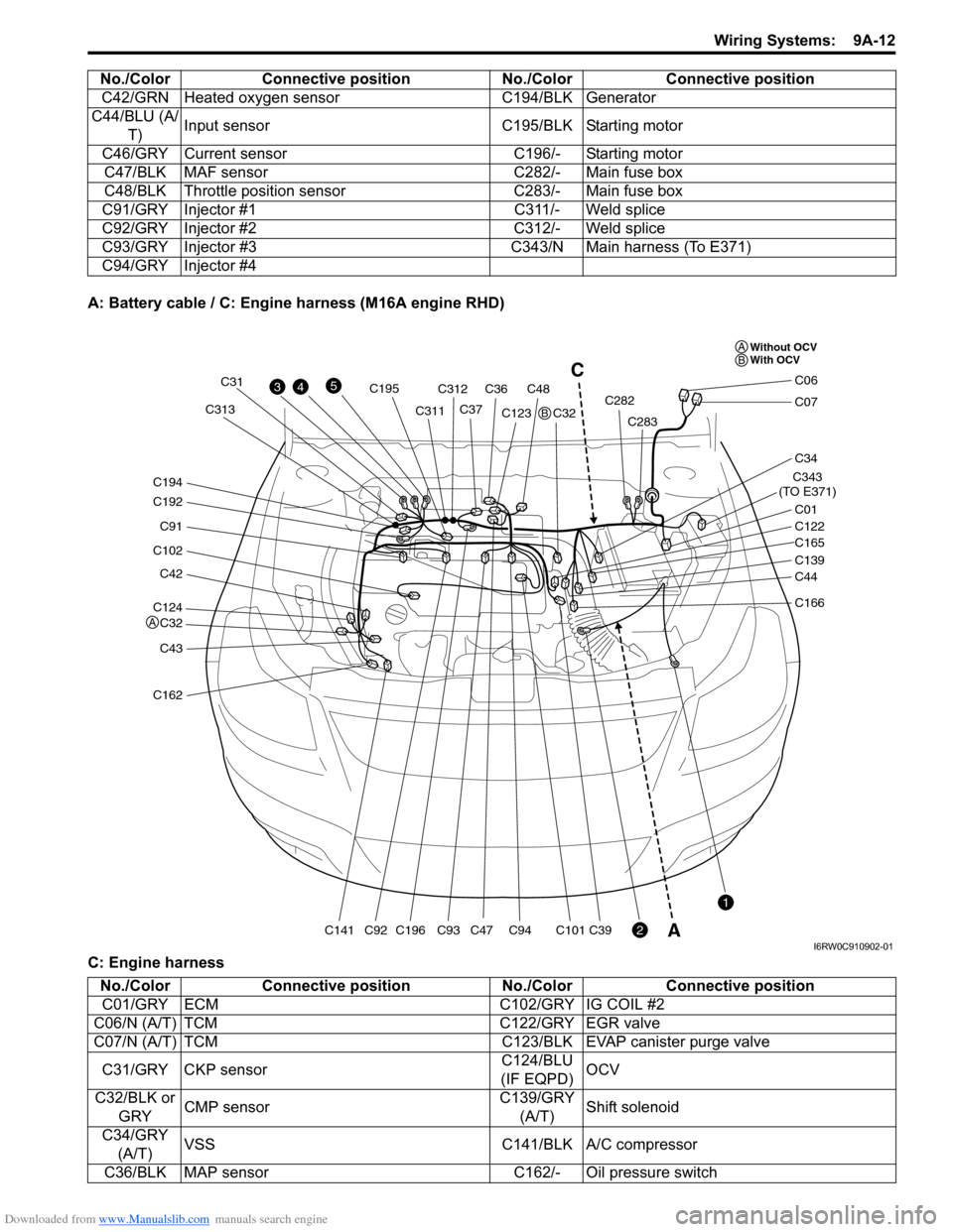
A: Battery cable / C: Engine harness (M16A engine RHD)
C: Engine harnessC42/GRN Heated oxygen sensor C194/BLK Generator
C44/BLU (A/
T)Input sensor C195/BLK Starting motor
C46/GRY Current sensor C196/- Starting motor
C47/BLK MAF sensor C282/- Main fuse box
C48/BLK Throttle position sensor C283/- Main fuse box
C91/GRY Injector #1 C311/- Weld splice
C92/GRY Injector #2 C312/- Weld splice
C93/GRY Injector #3 C343/N Main harness (To E371)
C94/GRY Injector #4 No./Color Connective position No./Color Connective position
C124
C32
C42
C102
C91
C192
C194
C43
C162
C141C196
C195
C93C94C101C39C92
C31
C311C313C312
C36C48
C37C123
C47C32C282
C283
C343
(TO E371)
C01
C34
C07
C06
C122
C165
C139
C44
C166
43
2
1
5C
A
Without OCV
With OCV A
A
B
B
I6RW0C910902-01
No./Color Connective position No./Color Connective position
C01/GRY ECM C102/GRY IG COIL #2
C06/N (A/T) TCM C122/GRY EGR valve
C07/N (A/T) TCM C123/BLK EVAP canister purge valve
C31/GRY CKP sensorC124/BLU
(IF EQPD)OCV
C32/BLK or
GRYCMP sensorC139/GRY
(A/T)Shift solenoid
C34/GRY
(A/T)VSS C141/BLK A/C compressor
C36/BLK MAP sensor C162/- Oil pressure switch
Page 1180 of 1556
Downloaded from www.Manualslib.com manuals search engine 9A-13 Wiring Systems:
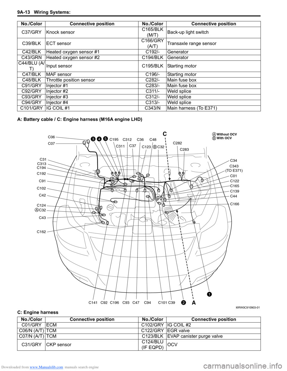
A: Battery cable / C: Engine harness (M16A engine LHD)
C: Engine harnessC37/GRY Knock sensorC165/BLK
(M/T)Back-up light switch
C39/BLK ECT sensorC166/GRY
(A/T)Transaxle range sensor
C42/BLK Heated oxygen sensor #1 C192/- Generator
C43/GRN Heated oxygen sensor #2 C194/BLK Generator
C44/BLU (A/
T)Input sensor C195/BLK Starting motor
C47/BLK MAF sensor C196/- Starting motor
C48/BLK Throttle position sensor C282/- Main fuse box
C91/GRY Injector #1 C283/- Main fuse box
C92/GRY Injector #2 C311/- Weld splice
C93/GRY Injector #3 C312/- Weld splice
C94/GRY Injector #4 C313/- Weld splice
C101/GRY IG COIL #1 C343/N Main harness (To E371)No./Color Connective position No./Color Connective position
C124
C32
C42
C102
C91
C192
C194
C43
C162
C141C196
C195
C93C94C101C39C92
C31
C311
C313C312
C36C48
C37C123
C47C32C282
C283
C343
(TO E371)
C01
C34
C07
C06
C122
C165
C139
C44
C166
43
2
1
5C
AWithout OCV
With OCV A
A
B
B
I6RW0C910903-01
No./Color Connective position No./Color Connective position
C01/GRY ECM C102/GRY IG COIL #2
C06/N (A/T) TCM C122/GRY EGR valve
C07/N (A/T) TCM C123/BLK EVAP canister purge valve
C31/GRY CKP sensorC124/BLU
(IF EQPD)OCV